A photocopy of this document is in the Navy Department Library. The original document is located in the World War II Command File of the Archives Branch, Naval History & Heritage Command.

The Navy Department Library
U.S. Radar
Operational Characteristics of Radar
Classified by Tactical Application
FTP 217
Prepared by Authority of the Joint Chiefs of Staff, by the
Radar Research and Development Sub-Committee of the Joint
Committee on New Weapons and Equipment
1 AUGUST 1943
WASHINGTON, D. C.
- The publication "U.S. Radar - Operational Characteristics of Available Equipment Classified by Tactical Application", short title FTP 217, is issued for the guidance of those concerned in planning of future operations.
- FTP 217 is effective upon receipt. It is a [formerly] SECRET [currently declassified] registered publication, and is to be transported, handled, and accounted for by U.S. Navy holders in compliance with U.S. Navy Regulations and the current edition of the Registered Publications Manual or by U.S. Army holders in accordance with A.R. 380-5. The Adjutant General's Office, Operations Branch, 2-B-939, Pentagon Building, Washington, D.C., is designated as the office of record, for U.S. Army holders.
- It is forbidden to make extracts from or to copy this publication without specific authority from The Joint Chiefs of Staff, except as provided for in Article 516 of the Registered Publications Manual. [Distribution currently unlimited].
- FTP 217 is not intended for use in aircraft. When not in use, it is to be given secure stowage as provided in the Registered Publications Manual or A.R. 380-5.
| /signed/ WILLIAM R. PURNELL Rear Admiral, U.S. Navy Deputy Chief of staff Commander-in-Chief, U.S. Fleet and Chief of Naval Operations |
/signed/ JOSEPH T. McNARNEY Lieutenant General, U.S. Army Deputy Chief of Staff |
TABLE OF CONTENTS
| Introduction | 1 | ||
| Shipborne Search Sets | 13 | ||
| CXAM and CXAM-1 | Long Wave Search Sets for Large Ships | 14 | |
| SC, SC-1, SC-2, and SC-3 | Long Wave Search Sets for Destroyers and Larger | 15 | |
| SK | Long Wave Search Set for Large Ships | 16 | |
| SG | Microwave Search Set for Destroyers and Larger | 17 | |
| SA and SA-1 | Long Wave Search Sets for Destroyers | 18 | |
| SH | Microwave Search and Fire Control Set for Cargo Ships | 19 | |
| SF | Microwave Search Set for Destroyer Escorts and Lighter | 20 | |
| SE | Microwave Search Set for Small Ships | 21 | |
| SL | Microwave Search Set for Small Ships | 22 | |
| SD-a, SD-1, SD-2, and SD-3 | Long Wave Search Sets for Submarines | 23 | |
| SJ | Microwave Search and Torpedo Control for Submarines | 24 | |
| SO Series | Microwave Search and Torpedo Control for Small Craft | 25 | |
| SN and *SQ | Portable Microwave Set | 26 | |
| *SW | Portable Medium Wave Set | 27 | |
| *SB | Portable Medium Wave Set | 27 | |
| Ship Fire Control Sets | 29 | ||
| Mark 3 | Medium Wave Fire Control for Main Batteries | 30 | |
| Mark 8 | Microwave Fire Control for Main Batteries | 31 | |
| Mark 4 and *Mark 12 | Medium Wave Fire Control for Dual Purpose Batteries | 32 | |
| *Mark 10 | Microwave Antiaircraft Fire Control | 33 | |
| *Mark 11 and *Mark 19 | Microwave Antiaircraft Fire Control | 34 | |
| Long-Range Aircraft Warning Sets | 35 | ||
| SCR-270-D | Mobile Long Wave Aircraft Warning Set | 36 | |
| SCR-271-D and SCR-271-E | Fixed Long Wave Aircraft Warning Set | 37 | |
| Seacoast Artillery Sets | 39 | ||
| SCR-582 | Fixed Microwave Seacoast Artillery Set | 40 | |
| *SCR-682 | Transportable Microwave Seacoast Artillery Set | 41 | |
| SCR-296-A | Fixed Medium Wave Coast Artillery Fire Control Set | 42 | |
| *Mark 16 | Mobile Microwave Search and Fire Control Set | 43 | |
| Searchlight Control Sets | 46 | ||
| SCR-268 and SCR-268-B | Mobile Long Wave Searchlight Control Set | 46 | |
| Anti-Aircraft Fire Control Sets | 47 | ||
| SCR-547 | Mobile Microwave radar-Optical Height Finder | 48 | |
| SCR-545 | Mobile Long wave Aircraft Search and Microwave AA Fire Control | 49 | |
| SCR-584 | Mobile Microwave Anti-Aircraft Fire Control Set | 50 | |
| GCI--Ground or Ship Control-of-Interception Sets | 51 | ||
| SCR-588 | Long Wave Aircraft Detector and GCI | 52 | |
| SCR-527 | Mobile Long Wave Aircraft Detector and GCI | 53 | |
| SCR-615-A and SCR-615-B | Microwave Aircraft Detectors for GCI | 54 | |
| *SCR-627 | Long Wave GCI | 55 | |
| *SM | Microwave Shipborne GCI Set | 56 | |
| AI -- Aircraft Interception Sets | 57 | ||
| SCR-540 | Long Wave AI Set | 58 | |
| SCR-520-B and SCR-720-A | Microwave AI Sets | 59 | |
| AIA | Microwave AI Set for Single-Seated Fighters | 60 | |
| Lightweight Aircraft Warning Sets | 61 | ||
| SCR-602-A and SCR-602-T6 | Light Transportable Aircraft Detectors | 62 | |
| *AN/TPS-1 (*SCR-602-T3) | Light Transportable Aircraft Detector | 63 | |
| *AN/TPS-3 (*SCR-602-T8) | Light Transportable Aircraft Detector | 64 | |
| ASV -- Air-to-Surface Search Sets | 65 | ||
| SCR-521-A or ASVC, and SCR-521-B or ASE | Long Wave ASV Sets | 66 | |
| ASA | Medium Wave ASV Set | 67 | |
| ASB and "ASB Series" | Medium Wave ASV Sets | 68 | |
| SCR-517-A, SCR-517-B or ASC-1, and SCR-517-C | Microwave ASV Sets | 69 | |
| SCR-717-A and SCR-717-B | Microwave Small-Package ASV Sets | 70 | |
| ASD | Microwave ASV Set | 71 | |
| ASG, ASG-1, AN/APS-2a, (ASG-2) and AN/APS-2 (ASG-3) | Microwave ASV Sets | 72 | |
| *AN/APS-3 (ASD-1) | Microwave ASV and Torpedo-Laying Set | 73 | |
| *AN/APS-4 (ASH) | Lightweight ASV and Interception Set | 74 | |
| Bombing Aids | 75 | ||
| AN/APQ-5 (RC-217) | Bombing Attachment to Microwave ASV Sets | 76 | |
| *AN/APS.15 | Microwave ASV and High Altitude Bombing Set | 77 | |
| Navigation Sets | 79 | ||
| SCR-518-A or AYA | High-Altitude Pulse Altimeter | 80 | |
| *SCR-718 | Pulse Altimeter | 81 | |
| AYB, AN/ARN-1 (RC-24 and AYD-5) and AN/APN-1 (AYF) | Low-Altitude FM Altimeters | 82 | |
| SCR-640, SCR-621 or YH, and *YJ | Long Wave Racons | 83 | |
| *AN/CPN-3 (*SCR-620 or *YK) and*AN/CPN-6 | Microwave Ground or Shipborne Racons | 84 | |
| *AN/TPN-1 and *AN/PPN-1 | Light Weight Long Wave "Eureka" Racons | 85 | |
| *AN/APN-2 | Airborne Long wave "Rebecca" Interrogator-Responsor | 86 | |
| LORAN | Long-range Navigation System | 87 | |
| IFF -- Identification Sets | 89 | ||
| IFF -- Introduction | 90 | ||
| SCR-535 or ABE, and ABD | Mark II Airborne Transpondors | 95 | |
| SCR-595, ABK or BK -- Mark III | Airborne or Shipborne Transpondors | 96 | |
| SCR-695 or ABF | Mark III Airborne Transpondor | 97 | |
| *AN/APX-1 | Mark III Airborne Transpondor | 98 | |
| *AN/APX-2 (ABJ) | Mark III Airborne IRT | 99 | |
| *AN/APA-1 | Pilot Repeat Indicator | 100 | |
| SCR-729 | Mark III Airborne IR | 100 | |
| *AN/APN-8 | Airborne Radar Transpondor beacon | 101 | |
| BL and *BM | Mark III (A Band) Shipborne IR | 101 | |
| BN | Mark III (A Band) Low Power Shipborne IR | 102 | |
| *BO | Mark III (G Band) High Power Shipborne IR | 102 | |
| MARK III IR'S FOR ARMY GROUND EQUIPMENT | 103 | ||
| Miscellaneous | 105 | ||
| MAD (Type 4B2, AN/ASO-1, AN/ASQ-1a, AN/AS1-3) | Magnetic Detectors | 106 | |
| AN/CRT-1 and AN/ARR-3 | Sono-Radio buoys | 107 | |
| Glossary of Terms | 109 | ||
| List of Equipments by Army-Navy Joint Designation | 113 | ||
* Available for issue in latter part of 1943.
What Is Radar?
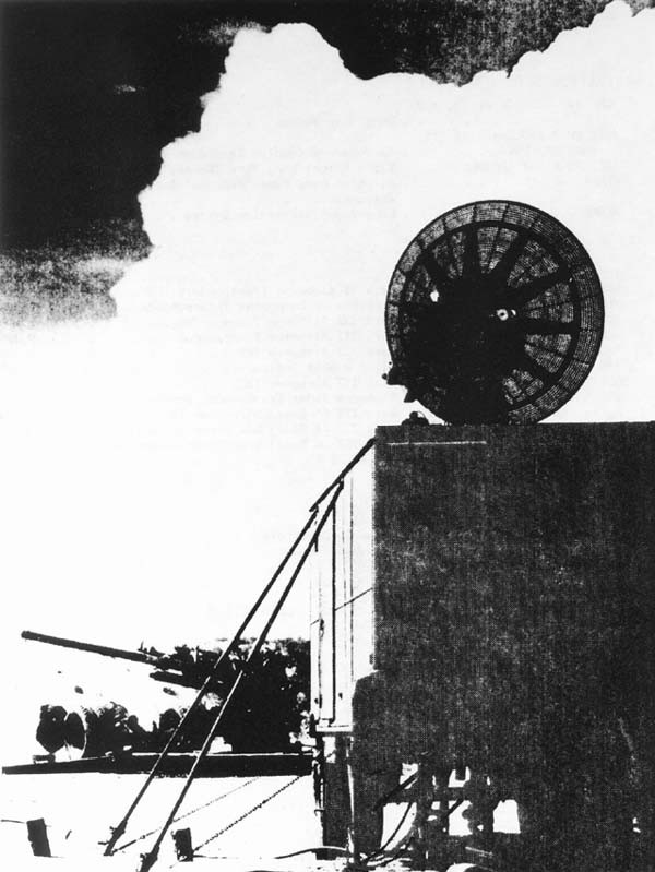
- RADAR -- synthetic word meaning Radio Direction And Ranging -- is an electronic device which locates ships and planes in darkness, fog, or storm. It has many military applications and has been effective in many battles of this war.
- As early as September, 1940, radar enabled British fighters to bring down 232 enemy planes in one day with a loss to themselves of only 40 planes and 12 pilots.
- Later, in 1942, radar enabled an American cruiser to surprise a formation of Japanese warships at night and sink 6 of them in total darkness.
- Again in the Pacific radar warned one of our carriers of enemy planes approaching at 70 miles. Fighters went up and shot down 18 planes out of 20.
- In North Africa, one radar ground station working with a squadron and a half of radar-equipped night-fighters shot down 29 enemy bombers and damaged two others in one month's operation.
--1--
--How Radar Works--
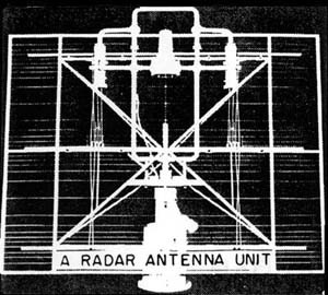
The principle upon which radar operates is simple. Briefly, it consists of sending out a short pulse of radio energy and receiving a portion of the same energy reflected back by objects in its path.
The energy sent out by a radar set is the same as that transmitted by ordinary radio. But unlike an ordinary radio set a radar set literally picks up its own signals. Thus the radar set transmits a short pulse of energy, receives its echoes, then transmits another pulse and receives its echoes. This out-and-back cycle is repeated from 60 to 5000 times a second.
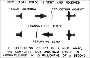
The extremely short time interval between the sending of the pulse and the reception of its echoes can be measured very accurately--even to one ten-millionth of a second. Since the speed at which the radio energy travels is known (it is the same as that of light) the range of any reflecting object can be obtained.
Furthermore, the transmitted energy is focused in a beam which can be pointed in any chosen direction. Hence the bearing of a reflecting object is also obtained.
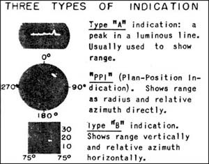
The echoes received by the radar appear not as sound signals, as is the case with ordinary radio, but as marks of light on a flourescent tube. The face of the tube--or scope, as it is usually called-may be marked with a scale of miles, or degrees, or both. Hence from the position of any signal on the scope an observer can tell at a glance the range and direction of the corresponding target. The three commonest types of scopes are shown in the sketch at the left.
Just as there are different types of scopes, there are many kinds of radar sets. They vary in size from those that can be carried by hand to those that weigh several thousand pounds. The design of a radar set depends upon the job it is intended to do, and radar serves many functions. The chief of these are described in the following pages.
--2--
What Radar Can Do
ACTUAL-SIZE PHOTOGRAPH of a radar "scope," taken in a plane flying over Nantucket Island. Circle on scope marks 10-mile radius. Note correspondence with geodetic chart (insert.)
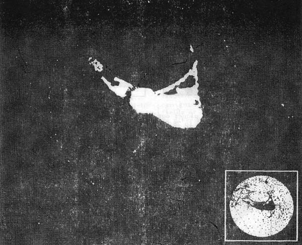
THIS PHOTOGRAPH ILLUSTRATES the clear definition between land and water provided by radar, as well as the sort of picture presented on one type of radar scope. Such definition, of course, is useful as an aid in navigation of planes and ships, in observing the movements of ships and convoys, in detecting targets at night, in shelling or bombing enemy vessels or coastal targets, or in mapping work.
This PPI scope has a flourescent screen so made that the signals from reflecting objects will persist for a few moments. Other types of scopes are shown on the following pages, illustrating some of the chief uses of radar. For most of these functions, several radar sets are now available. Details of design, operation and performance of specific sets are listed later in the book.
--3--
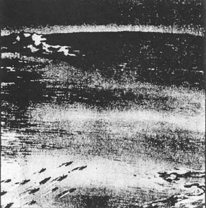
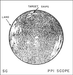
RADAR ENABLES ships to detect planes out to 100 miles and surface vessels to 28,000 yds, and to distinguish between friendly and enemy craft. It can be used to locate enemy units in night battles, to maintain convoy formation and to navigate.
Radar Controls Ship Gunfire
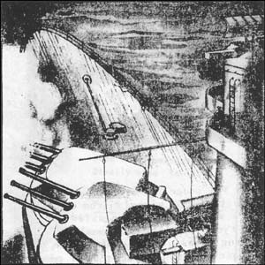
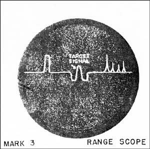
AFTER LOCATING SHIPS, radar provides range and bearing of targets to the guns, and permit the course of the enemy ship to be calculated more accurately than by any other method. Accurate and continuous determination of range rate allows the gunnery officer to alter fire to take into account the enemy ship's change in course.
--4--
Radar Defends Coastlines Against Ships
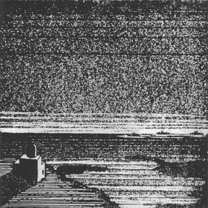
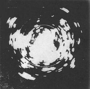
SHORE-BASED SETS can maintain a round-the-clock seaward search, detecting ships as far out as 45 miles. These sets can direct patrol craft to unidentified ships, can guide friendly ships through mine fields or fog, and can assign any targets to other radars having the specific function of coast artillery gun-laying.
Radar Gives Long-Range Warning of Planes
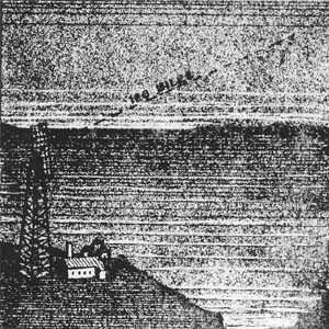
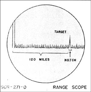
RADAR CAN DETECT high-flying planes as far away as 135 miles, and permit plotting of their location, approximate course and speed. Enough warning is given to allow fighter planes to take off, thus eliminating the need for a standing air patrol.
--5--
Radar Can Direct Searchlights
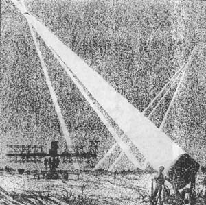
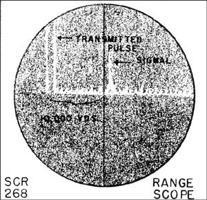
RADAR GIVES SEARCHLIGHT crews a 40,000-yd. warning and sufficient data so that planes will be struck instantly at least 90% of the time when the lights are turned on -- thus preventing planes from evading the beams.
Radar Directs Anti-Aircraft Fire
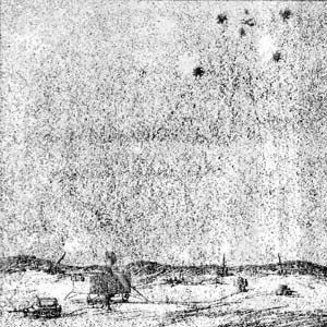
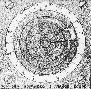
MOBILE RADAR provides range for anti-aircraft guns, day or night, more accurately than optical height finders, and can give continuously and automatically the elevation and azimuth of target regardless of its visibility.
--6--
Radar On Ground Directs Nightfighters
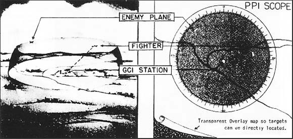
RADAR ENABLES a control officer at a fighter base to keep track of enemy planes and his own fighters within a range of 45 miles, and to direct fighters by voice to within 2 miles of enemy planes. From this range the fighter can, in daytime, complete the interception visually, or at night, the fighter can track the target to gun range by means of another radar set (AI) carried in his own plane.
Radar In Plane Leads Fighters To Gun Range
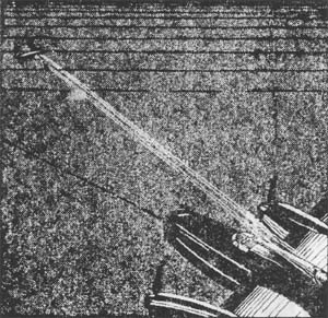
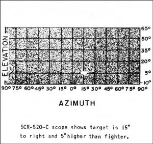
A NIGHTFIGHTER can detect an enemy plane by radar when the plane is 7 miles away, and reliability is certain at 4 miles. A CGI should direct a nightfighter to within 20,000 feet of the target, at which point the nightfighter's radar (AI) will permit tracking until the enemy plane is within firing range.
--7--
Radar Enables Planes To Detect and Bomb Ships
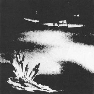
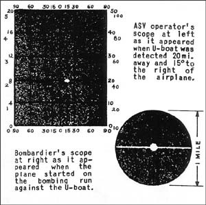
A RADAR-EQUIPPED PLANE can do blind bombing with the aid of a Norden bombsight attachment that is more accurate at low levels than a Norden bombsight itself in visual day bombing. At 5000 feet a plane with SCR-517 can detect a 10,000-ton ship 45 mi. away, a surfaced sub at 18 miles -- hence, can patrol sea lanes, shepherd convoys, and do reconnaissance in fleet operations regardless of night or bad weather.
Radar Guards Beachheads and Advanced Bases
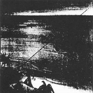
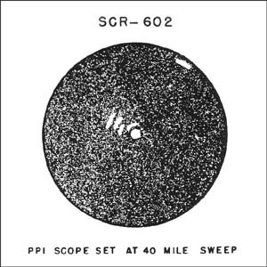
LIGHT-WEIGHT RADAR SETS may be used in warning a beachhead or advanced base of approaching enemy planes or ships (at night for example), or in directing beachhead operations from the first point of debarkation when landing barges have radar navigation equipment. A key for sending messages can be used with portable sets.
--8--
Radar Aids Navigation of Planes & Ships
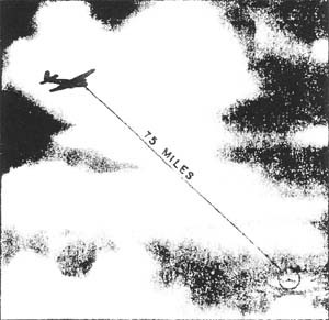
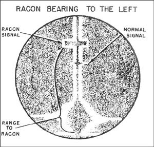
ONE RADAR DEVICE is a beacon (Racon) that emits coded signals in response to radiation from a plane or ship, keeping silent when not actually in use, and able to guide planes to a base or carrier 80 miles distant. Another device (Loran) enables ships to find their position to within 1 mile, as far as 1250 miles from shore.
Because of the clear definition between land and water provided by radar, as is illustrated in the scope photo of an island on page 3 of this book, important navigational aid can be given planes or ships at night, in fog or storm; e.g., in guiding planes to an island or coastal target.
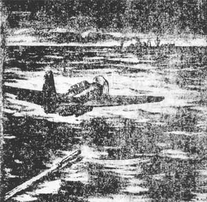
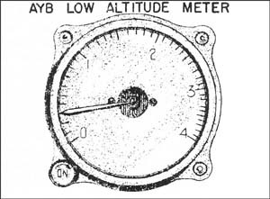
PLANE AT LEFT is at 30 feet. Low-level altimeters measure from 400 to 5 feet. Other radar altimeters can measure absolute altitude as high as 40,000 feet.
--9--
Limitations of Radar
As has been seen on the previous pages, radar can be useful in almost any military situation. But the successful use of radar demands an understanding of its properties.
Radar has several inherent limitations: it cannot "see" under water, for example, nor very far beyond the line of sight. Its range is affected to some extent by atmospheric conditions. Radar sometimes records signals from clouds, which to an inexperienced operator resemble signals from aircraft or ships. It is still a new weapon, rushed through production and into field use in so short a time that frequent instances of faulty operation and breakdown are encountered.
Further, the performance and operation of individual radar sets vary greatly. The most important factors in the performance of a set are the wavelength used and the proficiency of the operating and maintenance crews; in the set descriptions which follow the range of wavelength is indicated.
Sets in the shortest wavelength range are called microwave. those in the intermediate wavelength range are referred to as medium wave. Those employing the longest radar wavelengths (which are still shorter than the waves used by high-frequency radio communications) are designated long wave.
Most radar equipment now issued uses a long or medium wavelength. Sets employing these frequency ranges usually have a long range, which increases with the size of the antenna and the height at which it is mounted. The definition and angular accuracy, however, are poor. Choice of a location for these sets is most important, since the presence of hills, buildings, or other reflecting objects within view of the radar site will cause permanent echoes on the scope. Long wave ground or ship sets, too, give poor protection against distant surface vessels of low-flying planes. Usually, there are also gaps in the coverage against aircraft within the extreme detection range.
Microwave equipment has the advantage of sharper definition and greater angular accuracy. It also offers better coverage of objects at low elevation angles, and is less dependent upon careful choice of site. Most microwave sets now in production do not have as great a range against high-flying aircraft as that of long wave equipment. Gaps in coverage are less important in microwave sets, but there is likely to be poorer coverage against high-altitude planes.
The ability of radar to "see" under any conditions of visibility and to give continuous accurate values of target range and direction has considerably altered the military picture; but the full capabilities of this new facility can be realized only when all concerned appreciate its possibilities and requirements.
--10--
Radar in Planning
First, the commanding officer and his staff must have such an appreciation. They must understand that radar permits undertakings of a wholly new type to be carried out. For example, ships can be navigated at night at high speed in narrow waters with precision and safety, and can engage an unseen enemy with guns or torpedoes. By the use of radar beacons, aircraft can home with an accuracy measured in yards on an objective distant 80 miles or more.
The commanding officer and his staff must appreciate that the employment of radar by the enemy must always be assumed, and they must understand what this means in terms of their plans. Darkness, smoke, or fog must no longer be relied on for certain cover. Aircraft approaching an objective must no longer fly as high as possible to escape detection; better results will attend a very low approach or one which makes use of the radar "shadows" cast by mountains obstructing radar beams. The use of countermeasures to confuse or defeat the enemy's radar must be considered in planning crucial operations.
It must be understood that radar cover against air attack must be planned for the very earliest stages of a new occupation. Only by the timely alerting and the defensive facilities provided by radar will it be feasible to deal with the sustained air attack which can be mounted by a determined enemy.
Radar in Tactics
The tactical officer in the field must understand the power that radar gives him. Its use is so new that tactical doctrine is still being worked out, and an ingenious officer will sometimes be able to employ one of the sets described in the following pages in a military situation never contemplated by its designer.
For example, there is the case of a patrol bomber equipped with ASE, which located enemy ships and attacked them unsuccessfully. A squadron of motor torpedo boats not equipped with radar was available, and the aircraft was directed to cruise in the area and direct the PT boats to the target, using the general situation plot provided by the radar. The PT boats were thus enabled to make a successful attack.
--11--
Full reliance must be placed on radar in order that it may be wholly effective. In the Hood-Bismarck engagement, for example, the gunnery officer of the Hood had his choice between using optical and radar range information, which differed by 4000 yards. For his first salvo, he used the optical range value. There was no opportunity to fire another.
The Operation of Radar
Finally, the officer in charge of the actual operation of radar equipment must be resourceful, skillful, and well-informed. As has been remarked, technical difficulties with the equipment are all too frequent, and must often be dealt with without the help of adequate spares or test equipment. The radar officer must realize that the reliance which will be placed on the information provided by his equipment will largely depend on the reliability with which it has been made available.
He must be prepared at all times for the employment of countermeasures by the enemy, in an attempt to render our radar partly or wholly useless. In general, such measures can be dealt with by an experienced and resourceful radar officer.
He must understand that the proper interpretation of the signals presented by the radar equipment is most important. Spurious echoes from clouds must be recognized as such, the reliability of IFF indications must be maintained to avoid false alarms, and highly skilled interpretation of signals will even enable fairly accurate estimates to be made of the size and character of enemy forces from the radar signals they present.
Our Radar Equipment
Given this understanding and skillful use of radar by all concerned, we shall have the advantage of the enemy in this field. Experts assert that the state of technical development of U.S. Radar equipment described on the following pages is about one year in advance of that available to the enemy. The enemy is doing well with what he has got; it is only through conscientious and imaginative use that our better equipment can be made to count.
--12--
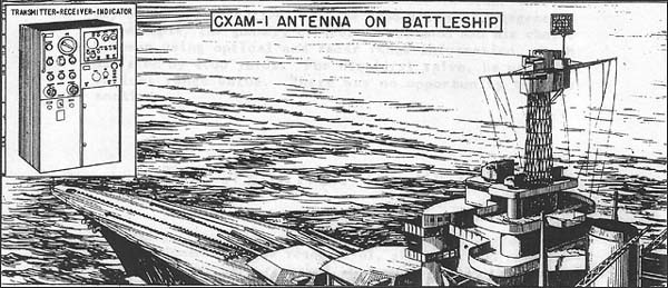
| DESCRIPTION AND USES: | Long-wave search sets for large ships. They provide range and bearing of surface vessels and aircraft, and are equipped with an "A" scope. (These sets are no longer in production.) |
|---|---|
| PERFORMANCE: | With antenna at 130 ft., reliable maximum range on large aircraft is 50 miles, and on large ship, 25,000 yards. Range accuracy is about ± 200 yds. Azimuth accuracy ± 3°. |
| INSTALLATION: | Sets have 9 components weighing a total of about 5000 lbs. Heaviest unit is the antenna, which, with pedestal, weighs 1500 lbs. Antenna proper measures 15' x 15'8". |
| PERSONNEL: | Minimum operating personnel: one per shift. |
| POWER: | Primary power required is less than 5 KW, 110 V. 60 cycles. Motor-generator is supplied with set if ship's power is not suitable. |
--14--
SC, SC-1, SC-2 and SC-3 Long Wave Search for Destroyers and Larger
![SC-2 on Destroyer [inset: receiver-indicator]. SC-2 on Destroyer [inset: receiver-indicator].](/content/history/nhhc/research/library/online-reading-room/title-list-alphabetically/u/operational-characteristics-of-radar-classified-by-tactical-application/_jcr_content/body/image_28.img.jpg/1432643325658.jpg)
| DESCRIPTION AND USES: | Long wave search sets, installed on destroyers and larger ships to search for planes and surface vessels and for control of interception. All sets have an "A" scope, provision for IFF connections, and work with a gyro-compass repeater. SC-2 and SC-3 also have PPI scopes, remote PPI's, and built-in BL and BI* antennas. |
|---|---|
| PERFORMANCE: | With antennas at 100', SC and SC-1 (without preamplifier) have a reliable maximum range of 30 miles on medium bombers at 1,000' altitude. With preamplifier, SC-1's range is extended to 75 miles -- the same as that of SC-2 and SC-3. Range accuracy of SC is ± 200 yards; later models have an accuracy of ± 100 yds. bearing accuracy of SC and SC-21 is ± 5°; of SC-2 and SC-3, ± 3°. There is no elevation control on any of the sets, but height can be estimated roughly from positions of minimum signal strength. |
| TRANSPORTABILITY: | Shipment includes spares for each set. If separate generator is needed, it is included in shipment. Not air transportable. |
| INSTALLATION: | Both SC and SC-1 have 5 components weighing a total of 1800 lbs. SC-2 has 6 components weighing a total of 3,000 pounds. Weights and dimensions of antenna assemblies are 450 lbs. 6'111/2" x 8'6" for SC and SC-1; 478 lbs. 4'6" x 15' for SC-2 and SC-3. Antennas should be mounted as high as possible, preferably 100 feet or more, above other superstructures. |
| PERSONNEL: | One operator per shift is minimum on all 3 sets. |
| POWER: | SC and SC-1 require primary power of 1500 watts at 115 volts, 60 cycles. SC-2 and SC-3 require 2500 watts at 115 volts, 60 cycles. All sets use ship's power of 115 volts, 60 cycles; transformer, if ship's power is 440 volts AC or 220 volts AC; motor generator if ship's power is DC. |
* BI is a component of the Mark IV IFF system omitted from this volume.
--15--
SK Long Wave Search Set for Large Ships
![SK Installed on Battleship [inset: receiver-indicator]. SK Installed on Battleship [inset: receiver-indicator].](/content/history/nhhc/research/library/online-reading-room/title-list-alphabetically/u/operational-characteristics-of-radar-classified-by-tactical-application/_jcr_content/body/image_29.img.jpg/1432643351444.jpg)
| DESCRIPTION AND USES: | Long wave search set for large ships. Furnishes range and bearing of surface vessels and aircraft, and can be used for control of interception. Set has both "A" and PPI scopes, provisions for operating with remote PPI's and for IFF connections, and built-in BL and BI* antennas. |
|---|---|
| PERFORMANCE: | Reliable maximum range, with antenna at 100', is 100 miles on medium bombers at 1,000' altitude. Range accuracy is ± 100 yards. Azimuth accuracy, ± 3°. There is no elevation control, but elevation can be estimated roughly from positions of maximum, and minimum signal strength |
| TRANSPORTABILITY: | Shipment includes spares, with tubes for 400 hours, and separate generator if ship's power is DC. Not air transportable. |
| INSTALLATION: | SK has 10 components weighing approximately 5000 lbs. Heaviest unit (2400 lbs.) is the antenna assembly. Antenna measures 15' x 16'9". Antenna should be 100 ft. or more above water. |
| PERSONNEL: | Minimum operators required are one per shift. |
| POWER: | Primary power required is 3500 watts, 115 volts, 60 cycles. Source of power is ship's power of 115 volts, 60 cycles. |
* BI is a component of the Mark IV IFF system omitted from this volume.
--16--
SG Microwave Search Set for destroyers and Larger
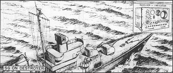
| DESCRIPTION AND USES: | Microwave search set installed on destroyers and larger ships to search for enemy surface ships, to coordinate attack by surface vessels, and to aid in navigation. Furnishes range and bearing on PPI and "A" scopes. SG has provisions for IFF (identification) connections, and equipment is being supplied for connecting to remote PPI's. |
|---|---|
| PERFORMANCE: | Reliable maximum range is 15 miles on large ships; with antenna height of about 100 feet. Range accuracy is ± 100 yds. Azimuth accuracy: ± 2°. |
| TRANSPORTABILITY: | Complete shipment includes spares and testing equipment, and is crated in 15 units weighing about 4289 lbs. Largest package is 13'4" x 12" x 10" and weighs 359 lbs. Heaviest package (1425 lbs.) is 28" x 41" x 80". |
| INSTALLATION: | SG has 5 components weighing approximately 2200 lbs. Heaviest unit (1180 lbs.) is the transmitter-receiver -- 737/8" x 34" x 223/8". Antenna, which weighs 350 lbs. with pedestal and measures 44" x 491/2" in diameter, should be mounted as high as possible, preferably more than 100 feet above water and above adjacent superstructure. |
| PERSONNEL: | One man per shift is minimum requirement. |
| POWER: | Primary power required is 115 volts, 60 cycles: 2.8 KVA. Source is ship's main line. |
--17--
SA and SA-1 Long Wave Search Sets for Destroyers
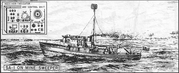
| DESCRIPTION AND USES: | Long wave search sets. SA is installed on destroyers or vessels of similar size, SA-1 on ships lighter than destroyers. Both sets provide range and bearing on "A" scopes only; PPI's will be added later. SA has provisions for transmitting range and bearing to remote repeaters. Both sets have provisions for IFF connections, for identification of targets, and the SA also has built-in BL and BI* antennas. |
|---|---|
| PERFORMANCE: | For SA the estimated reliable range is 40 miles on medium bombers at 10,000', with antenna at 100'. Range accuracy is ± 100 yds. Bearing accuracy, ± 1°. For SA-1 the estimated reliable range is 25 miles on large aircraft, 8 miles on battleship. Range accuracy is ± 100 yds. Bearing accuracy is 3° to 5° on SA-1, 1° on SA (lobe switching). There is not elevation control on either set. |
| TRANSPORTABILITY: | Shipments of both sets include spares. SA is packed in 24 units, weighing when crated 3300 lbs. Largest SA package is 110" x 69" x 331/2", and weighs 642 lbs. SA-1 is packed in 23 units weighing when crated 2444 lbs. Largest package is 78" x 651/2" x 341/2" and weighs 338 lbs. |
| INSTALLATION: | SA has 12 components and weighs a total of approximately 1500 lbs. SA-1 has 12 components and weighs a total of approximately 900 lbs. SA antenna measures 5' x 8'8". Including pedestal, it weighs 500 lbs. SA-1 antenna measures 5' x 6', and weighs (including pedestal) 100 lbs. On both sets the antenna should be mounted as high as possible, preferably 100 feet or more above the water. |
| PERSONNEL: | For both sets a minimum of one operator per shift is required. |
| POWER: | Primary power required by SA is 1950 watts at 115 volts, 60 cycles; by SA-1, 2 KVA, 115 volts, 60 cycles. |
* BI is a component of the Mark IV IFF system omitted from this volume.
--18--
SH Microwave Search and fire Control set for Cargo ships
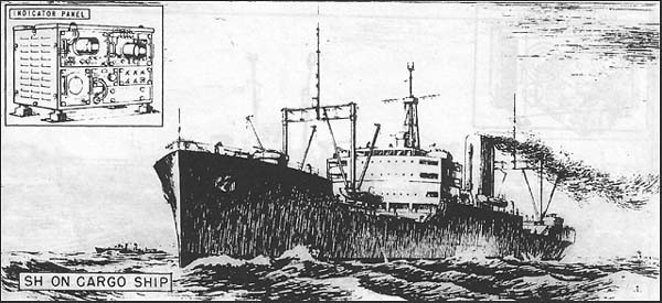
| DESCRIPTION AND USES: | Microwave search and fire control set, for cargo ships and large auxiliary transports. Range and bearing are shown on a PPI scope and an "A" scope. Lobe-switching is used for fine determination of bearing. Used to detect surface vessels, to aid navigation, and to direct gunfire. |
|---|---|
| PERFORMANCE: | With antenna at 100', SH has an estimated reliable range of 10 miles on large ships. Range accuracy is ± (15 yds. + 1% of measured range). Bearing accuracy is ± 1°. |
| TRANSPORTABILITY: | SH is packed in 16 units for shipment, including spares. Total crated weight is 4468 lbs. Largest package is 44" x 43" x 61" and weighs 910 lbs. |
| INSTALLATION: | Set has 9 components, weighing a total of approximately 2770 lbs. Antenna, which weighs 700 lbs. and measures 51" x 361/2" in diameter, should be mounted as high as possible. |
| PERSONNEL: | One operator per shift is required for each set. |
| POWER: | Power required is 2.3 KVA, 115 V., 60 cycles. A transformer is supplied for operation from 440-volt supply. |
--19--
SF Microwave Search Set for Destroyer Escorts and Lighter
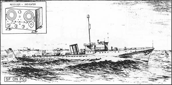
| DESCRIPTION AND USES: | Microwave set installed on destroyer escorts and lighter vessels for surface vessel search, navigation, and fire control. Provides range and true bearing on "A" and PPI scopes. Beginning with serial No. 525, sets will also be equipped for remote PPI's. There are provisions for IFF connections for identification of targets. |
|---|---|
| PERFORMANCE: | estimated reliable range is 15 miles on large ship, with antenna height of about 100 ft. Range accuracy is ± (1% + 100 yds.) Azimuth accuracy is ± 2°. |
| TRANSPORTABILITY: | Shipment includes spares for approximately 1500 hours. Complete shipment is packed in 13 boxes (including spare parts), the largest of which is 33" x 35" x 42". When crated, the shipment weighs 2200-2300 lbs. |
| INSTALLATION: | SF has 10 components, weighing a total of approximately 900 lbs. Heaviest unit (300 lbs.) is the motor generator--161/4" x 401/4" x 131/2". Antenna, which weighs 125 lbs. and measures 361/4" high by 303/4" in diameter, should be mounted as high as possible, with transmission line not exceeding 50 ft. in length. |
| PERSONNEL: | Minimum operating personnel required: one per shift. |
| POWER: | Primary power required is less than 2 KW. Source of power is 400 cycle, 115 volt DC motor generator and 440 V 3 phase AC motor. Generator is supplied with set. |
--20--
SE Microwave Search Set for small Ships
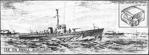
| DESCRIPTION AND USES: | Microwave search set, installed on small vessels and cargo ships, and used to detect surface vessels and aid in navigation. Set is equipped with an "A" scope, and has provisions for IFF (identification) connections. |
|---|---|
| PERFORMANCE: | SE, with antenna height of 100' has estimated reliable ranges of 12 miles on large ships, 8 miles on destroyers, and 4 miles on surfaced submarines. Range accuracy is ± 100 yds. + 15 of range. Azimuth accuracy is ± 2°. |
| TRANSPORTABILITY: | Packed in 19 units for shipment, weighing a total of 3300 lbs. Largest package is 55" x 42" x 64" and weighs 510 lbs. |
| INSTALLATION: | Set consists of 8 components weighing a total of approximately 2770 lbs. Antenna assembly weighs 280 lbs., and measures 581/2" x 483/4" x 261/2". It should be installed as high as possible on the ship. |
| PERSONNEL: | One operator per shift is required. |
| POWER: | Required power of 2.1 KVA is provided by motor generator, supplied from ship's power of 32 V. DC or 115 V. DC. |
--21--
SL Microwave Search Set for Small Ships
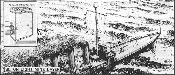
| DESCRIPTION AND USES: | Microwave search set for small ships. Furnishes range and true bearing of surface vessels on PPI scope. The set has provisions for IFF connections. |
|---|---|
| PERFORMANCE: | Estimated reliable range, with antenna at 100', is 20 miles on large ships. Range accuracy is ± 25 yards or 5% of full scale. Azimuth accuracy, ± 2°. |
| TRANSPORTABILITY: | Complete shipment, including spares and testing equipment, is packed in 11 units weighing a total of 2972 lbs. Largest package is 57" x 57" x 55" and weighs 600 lbs. Heaviest package weighs 862 lbs. |
| INSTALLATION: | SL has 3 components weighing a total of approximately 1300 lbs., plus power conversion equipment if needed. Antenna, which weighs 300 lbs. with hood and measures 45" x 48" in diameter, should be mounted as high as possible above water. |
| PERSONNEL: | Minimum operating personnel required is one man per shift. |
| POWER: | Power required is 1.4 kW, 115 V. 60 cycles. |
--22--
SD-A, SD-1, SD-2, and SD-3 Long Wave Search for Submarines
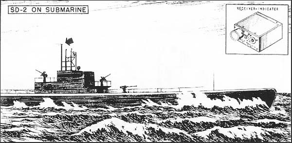
| DESCRIPTION AND USES: | Long-wave aircraft warning sets. SD-a, SD-1, and SD-2 are installed on submarines and give range only. SD-3, for small auxiliaries, supplies range and bearing. All sets are equipped with "A" scopes, and have provisions for IFF (identification) connections. |
|---|---|
| PERFORMANCE: | SD-a, SD-1 and SD-2, with antenna at 40' above water, have a reliable maximum range of 15 miles on medium bombers at 10,000' altitude. SD-3, with antenna at 80 ft. has a reliable maximum range of 25 miles on a medium bomber at 10,000'. Range accuracy is ± 500 yards. Bearing accuracy of SD-3 is ± 10°. |
| TRANSPORTABILITY: | There is no standard packing procedure for SD-a. SD-1 is packed in 20 units, SD-2 in 17, and SD-3 in 23. The heaviest package for each of these sets is 417 lbs. When crated SD-1 weighs 2036 lbs; SD-2, 1318 lbs; SD-3, 2548 lbs. |
| INSTALLATION: | The number of components and approximate total weight of each set are: SD-a -- 8 units, 500 lbs; SD-1 -- 6 units, 800 lbs; SD-2 -- 8 units, 550 lbs; SD-3 -- 9 units, 700 lbs. In each set the transmitter is the heaviest unit, weighing 300 lbs. Antenna assembly of SD-a, SD-1 and SD-2 weighs 34 lbs; of SD-3, 78 lbs. They should be mounted as high as possible above the water. |
| PERSONNEL: | Each set requires one operator per shift. |
| POWER: | For SD-a, SD-1, and SD-2, the primary power required is 115 volts, 60 cycles, 1130 watts. SD-3 requires 1277 watts. |
--23--
SJ Microwave Search and Torpedo Control for Submarines
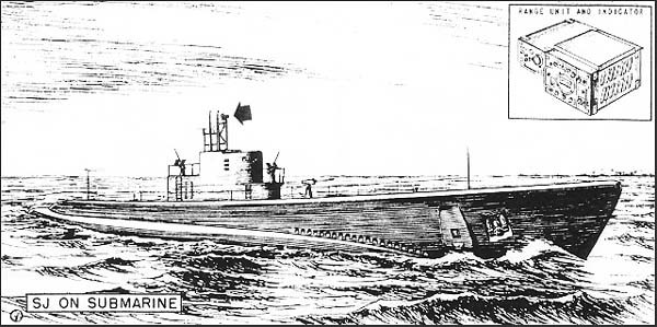
| DESCRIPTION AND USES: | Microwave search and torpedo-control set for submarines only. Present sets have an "A" scope only and use lobe-switching for fine determination of bearing. Later sets will also be equipped with PPI scopes. Set has provisions for IFF connections. For torpedo launching, Mark 1, 2, or 3 torpedo data computer is used. |
|---|---|
| PERFORMANCE: | Reliable maximum range, with antenna at 33', is 5 miles on a medium ship. Range accuracy, ± (15 yards + 0.1%). Azimuth accuracy, ± 1/4°. |
| TRANSPORTABILITY: | Complete shipment includes spares for 80 days, is packed in 22 units, and weighs when crated a total of 3022 lbs. Largest package is 50" x 20" x 20", and weighs 507 lbs. |
| INSTALLATION: | SJ has 14 components weighing a total of 1850 lbs. Motor generator is heaviest unit - 440 lbs., 145/8" x 421/42" x 137/16". Antenna, which weighs 35 lbs. and measures 211/2" x 30" x 195/8", should be mounted as high as possible. |
| PERSONNEL: | Minimum operating personnel: one per shift. |
| POWER: | Primary power required is 1.5 KVA, 115 volts, 60 cycles. Motor generator is supplied with set, if ship's power is not suitable. |
--24--
SO Series Microwave Search and Torpedo Control for Small Craft
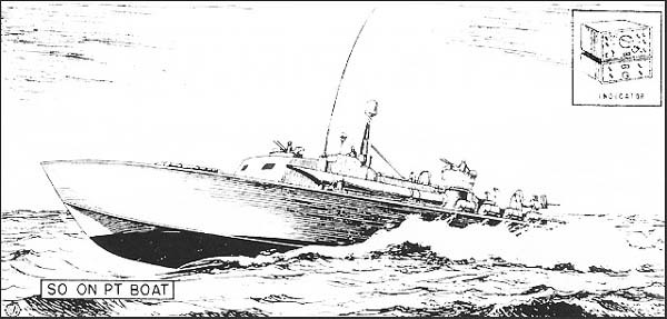
| DESCRIPTION AND USES: | Microwave search set and torpedo control for small craft. SO and SO-3 are installed on PT boats; SO-1, SO-2, and SO-4, on escort and patrol vessels. An SO-7M, to be mounted in a one-ton reconnaissance car, is contemplated for Marine Corps use. Sets provide range and bearing of planes and surface vessels on a PPI scope. All later sets will work with gyro-compass repeaters and show true bearing indication on the PPI. There are provisions for IFF identification connections. |
|---|---|
| PERFORMANCE: | Estimated range with antenna at 15' is 8 miles on a large ship. Range accuracy is ± 500 yards. Azimuth accuracy is ± 4°. |
| TRANSPORTABILITY: | Complete shipment is packed in 7 units, and with crating weighs 1161 lbs. Largest package is 1141/2" x 38" x 24" and weighs 420 lbs; but tripod can be shipped without packaging box when air transport is necessary, thus reducing the weight from 420 lbs. to 165 lbs. |
| INSTALLATION: | SO has 8 components weighing approximately 375 lbs. Heaviest unit is the motor alternator and modulator assembly -- 151/2" x 141/2" x 241/2" -- with a weight of 93 lbs. Antenna assembly, which weighs 59 lbs., should be 15 ft. above water, preferably higher. |
| PERSONNEL: | Minimum operating personnel: one per shift. |
| POWER: | Required power of 400 cycle 115 volts is supplied by motor generator, furnished with set. Different models of SO are supplied with motor generators suitable for various ships' power. |
--25--
SN and *SQ Portable Microwave Sets
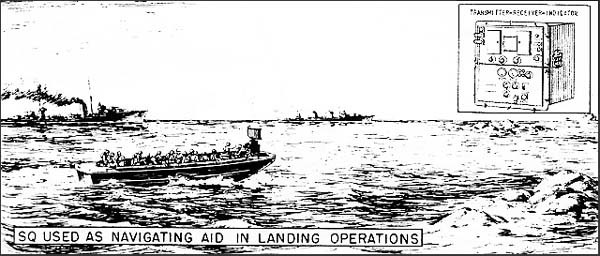
| DESCRIPTION AND USES: | Portable microwave set, used as standby equipment for short-range search and as a navigational aid. Sets can be stowed on ships below armor and set up on deck when other radars have been damaged, or can be set up on landing barges, or carried short distances by hand for use on beaches. Both sets provide range and bearing, and SQ has provisions for IFF identification connections. SN has an "A" scope only; SQ presents "B", B and PPI indication, as desired, on a single scope. |
|---|---|
| PERFORMANCE: | With antenna at 20', estimated reliable range of SN is 5 miles on a large ship; of SQ, 6 miles. Range accuracy is ± (2% plus 150 yards). Azimuth accuracy, ± 3°. |
| TRANSPORTABILITY: | Shipment includes spares and is air transportable. SN when crated has 5 packages and weighs 726 lbs., the heaviest package weighing 231 lbs. and the largest package being 33" x 26" x 39". The total weight of SQ when crated will be about 100 lbs. heavier than SN. |
| INSTALLATION: | Without motor drive (approx. 100 lbs.) and spare parts (approx. 85 lbs.) SN weighs about 265 lbs. and SQ weighs about 350. Heaviest SN unit is the modulator-rectifier-indicator -- 18" x 17" x 231/2" with a weight of 153 lbs. Heaviest SQ component is modulator-rectifier-indicator -- 22" x 20" x 21" with weight of 170 lbs. The sets should be as high as possible above water. |
| PERSONNEL: | For both sets the minimum personnel required is one per shift. |
| POWER: | SN requires 300 W at 90-130 V, 60 cycles. SQ requires 350 W at 90-130 V, 60 cycles. Generators may be supplied if needed. |
* Available for issue in latter part of 1943.
--26--
*SW Portable Medium Wave Set
| DESCRIPTION AND USES: | Portable medium wave aircraft detector used by Naval and Marine Corps aircraft and amphibious forces as a pack set for "jiggers" operation -- advanced bases, isolated troop concentrations, small military installations. Range and bearing are supplied with "A" type indication. |
|---|---|
| PERFORMANCE: | Estimated reliable range with antenna 10' above ground is 40 miles on a medium bomber at 1,000'. Bearing accuracy is approximately 10°. |
| TRANSPORTABILITY: | Shipment includes generator and spares for maintenance in the field. When crated in 6 packages the complete set weighs less than 500 lbs. The largest package weighs 72 lbs. and is 11/2' x 6' x 1'. |
| INSTALLATION: | Site should be elevated, but this requirement is not critical. Station can be constructed in 10 minutes by 4 men. The set has 6 components weighing a total of 300 lbs. |
| PERSONNEL: | 6 men are recommended personnel for 24-hour operation and maintenance. |
| POWER: | Primary power of 500 watts, 115 V., 400 cycles is supplies by a gasoline-driven motor generator requiring 100 octane or ordinary auto fuel. |
*SB Portable Medium Wave Set
| DESCRIPTION AND USES: | Medium wave portable search set for detection of planes and surface vessels at advanced bases. Set provides range and bearing, and is equipped with an "A" scope. |
|---|---|
| PERFORMANCE: | Reliable range is not known. Range accuracy is 1,000 yards. Azimuth accuracy about ± 5°. |
| TRANSPORTABILITY: | Complete shipment, including antenna, is packed in 3 units and weighs 672 lbs. Largest package is 56" x 26" x 30" and weighs 251 lbs. |
| INSTALLATION: | Set has 3 components weighing a total of approximately 500 lbs., and can be installed in a tent in 30 minutes. Antenna height is 13' above ground. Heaviest unit (177 lbs.) is carrying case for transmitter -- 275/32" x 1715/32" x 331/16 |
| PERSONNEL: | Two operators per set are minimum requirement. |
| POWER: | Primary power required is 1.5 KVA, 800 cycles, 115 volts. Power source is gasoline-driven generator, supplied with set. |
* Available for issue in latter part of 1943.
--27--
[B L A N K]
--28--
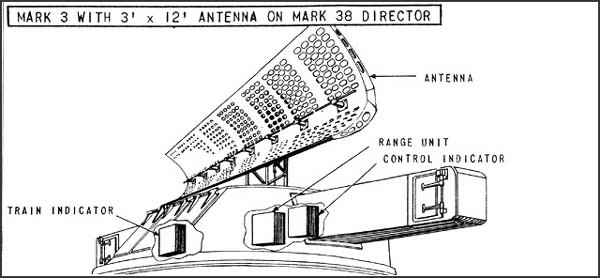
| DESCRIPTION: | Medium wave fire control for main batteries. Type "A" range indication and pip-matching for train. Has provisions for IFF connections, for identification of targets. Search radar designates target area. |
|---|---|
| USES: | Furnishes bearing and range to the mark 34 and Mark 38 directors for guns 6" or larger. It is not readily suitable for spotting the fall of the shot, except in range. |
| PERFORMANCE: | Reliable maximum range is 16,000 yds. for destroyer targets, 28,000 for battleships; minimum range is 1,000 yds.; range accuracy ± 40 yds. Azimuth accuracy is ± 4 mils for 6'x6' antenna or ± 2 mils for 3'x12' antenna. |
| TRANSPORTABILITY: | Radar is packed in 7 or 8 cases, weighing 3700 lbs., plus crated antenna mount. |
| INSTALLATION: | Of the seven components, the control-indicator, range units and train indicator are installed in the director. Equipment has either 3'x12' or 6'x6' antenna. |
| PERSONNEL: | One range operator and one maintenance man per set, in addition to regular director personnel, are required. |
| POWER: | Primary power required is 2.2 KW, 115 V, 60-cycle single phase, derived from ship's generators. |
--30--
Mark 8 Microwave Fire Control for Main Batteries
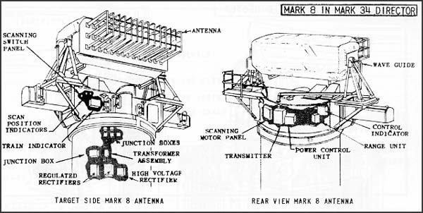
| DESCRIPTION: | Microwave fire control for main batteries. "A" and B indication. Search radar provides target designation. Equipment has provisions for IFF connections, for identification of targets. |
|---|---|
| USES: | Mark 8 is used with the gun directors Mark 34 and 38. It provides both bearing and range. It permits spotting in range and deflection -- it being possible to detect shell splashes. The equipment is for use with guns 6" and larger. |
| PERFORMANCE: | Reliable maximum range (on cruisers with antenna 120 ft. above water): 40,000 yards. Reliable minimum range: 500 yards. Range accuracy: ± (15 yards + 0.1% of range.) Bearing accuracy: 0.1° to 2 mils. Elevation limits: +55° to -20° for level; no cross-level. |
| TRANSPORTABILITY: | Shipment includes spares for a year and testing equipment. Complete shipment is packed in 47 boxes, weighing (spares included) a total of 14,485 lbs. |
| INSTALLATION: | The 13 components of Mark 8 are installed in or near the director, as shown in the above drawing. |
| PERSONNEL: | Minimum personnel is 1 operator and 1 maintenance man, plus director crew. |
| POWER: | Primary power required: 4 KW, 440 V, 3 phase, 60 cycles. Source of power is ship's supply. |
--31--
Mk 4 and *Mk 12 Medium wave Fire Control for dual Purpose batteries
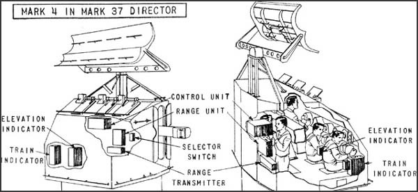
| DESCRIPTION: | Medium wave fire control for dual purpose batteries. "A" type range indicator and two pip-matching train and elevation indicators. Search radar provides target designation. Equipment has provisions for IFF connections for identification of targets. |
|---|---|
| USES: | Mark 4 is used on the all-purpose directors Mk. 33 and Mk. 37 with 5-inch guns. It furnishes elevation, bearing, and range, though at elevation angles below 10° the elevation angle is likely to be in error. Set is useful in getting a solution into the computer before the target gets into the range of visibility. Mark 12 will be a higher-powered set which will replace the Mark 4 in the Mark 37 director (square-backed type). |
| PERFORMANCE: | Reliable maximum ranges for mark 4: 35,000 yds. on PBY at 5,000', 16,000 yds. on destroyers, 25,000 yds. on battleships. Minimum range, 1,000 yds. Range accuracy, ± 40 yds. Bearing limits, 720° for director train. Bearing accuracy ± 4 mils. Elevation limits, +110° to -20°. Elevation accuracy, (above 10°) ± 4 mils. For Mark 12, maximum reliable range on PBY is 40,000 yds. Range accuracy will be ± 25 yds., accuracy in elevation (above 7°) and reading will be ± 2 mils. |
| TRANSPORTABILITY: | Radar is packed in 7 or 8 cases weighing 3800 lbs., plus crated antenna mount. Testing equipment and spares for one year are included. |
| INSTALLATION: | Mark 4 will have the control-indicator, range unit, and two train and/or elevation indicators mounted in the director. Mark 12 installation will be similar, but there will be four train and/or elevation indicators in the director. |
| PERSONNEL: | One radar range operator and one maintenance man are required in addition the director crew. |
| POWER: | Primary power required is 2.4 KW, 115 V, 60-cycle single phase, supplied by ship's generators. |
* Available for issue in latter part of 1943.
--32--
*Mark 10 Microwave Antiaircraft Fire Control
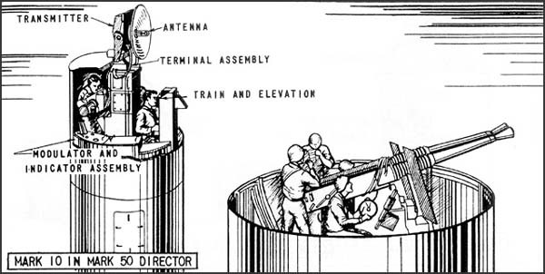
| DESCRIPTION: | Microwave AA fire control for Mark 50 directors. |
|---|---|
| USES: | The Mark 50 is used with 40 mm guns, and may be used with 3" or 5" AA guns when proper ballistics are available. The Mark 10 radar gives both direction and range of target, range by means of "A" indication, direction by a moving spot indicator. Search radar provides target designation. Equipment has no provisions for IFF identification connections. |
| PERFORMANCE: | Reliable maximum range: Mark 10, Mods. 0 and 1 -- 10,000 yds; Mods. 2 and 3 -- 15,000 yds. Minimum range; 300 yds. Range accuracy ± (15 yds. + 0.1% of range.) Bearing accuracy ± 0.25°. Elevation limits: 100° elevation, 25° depression. Elevation accuracy: ± 0.25°. |
| TRANSPORTABILITY: | Set, including spares for one year, is packed in 17 boxes. The largest is 75" x 36" x 36" and weighs 1200 lbs. Total weight of shipment when crated is 2760 lbs. |
| INSTALLATION: | Mark 10 consists of approximately 7 components. Most of these, including the transmitter, modulator, and all indicators, will be installed in the director. Their total weight will be about 1200 lbs. |
| PERSONNEL: | Minimum operating personnel: 1 radar range operator and one director operator who points by either radar or optics; minimum maintenance, one. |
| POWER: | Primary power required is 1.7 KW, 115 V, 60 cycles, single phase. Source of power is ship's line. |
* Available for issue in latter part of 1943.
--33--
*Mark 11 and *Mark 19 Microwave Antiaircraft Fire Control
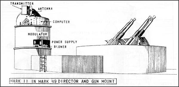
| DESCRIPTION: | Microwave AA fire control for automatic weapons. |
|---|---|
| USES: | Mark 11 furnishes range only on circular "A" scope; Mark 19 provides range on "A" scope, and bearing and elevation on moving spot indicator. Search radar designates target area. No provisions for IFF identification of targets. |
| PERFORMANCE: | For Mark 11, reliable maximum range on medium planes is 6,000 yards, reliable minimum range is 600 yards; range accuracy is ± 70 yds. Director train is unlimited. Elevation limits are from -30° to ± 115°. Mark 19 has a reliable maximum range of 12,000 yds. on medium bombers; a minimum range of 400 yds., and a range accuracy of ± (15 yds. + 0.1% of range). Bearing accuracy is ± 4 mils. Elevation accuracy (above 10°) is ± 4 mils. |
| TRANSPORTABILITY: | Shipment includes spares for a year, and will be air transportable. |
| INSTALLATION: | For the Mark 11, all components except receiver and control-indicator are mounted on or within the director. For the Mark 19, all control units will be mounted below deck. |
| PERSONNEL: | Minimum operating personnel required: 1 radar range operator, 1 director operator who points by optics or radar. For normal operations all day, 5 men are recommended. |
| POWER: | Primary power required for Mark 11 is 750 watts, 115 V, 60 cycles, single phase; for Mark 19, 1.4 KW, from ship's supply. |
* Available for issue in latter part of 1943.
--34--
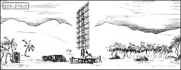
| DESCRIPTION: | Six-vehicle mobile, long wave early warning aircraft detector. Azimuth and range supplied. Set is equipped with "A" scope. | ||||||||||
|---|---|---|---|---|---|---|---|---|---|---|---|
| USES: | To establish a screen of warning which provides information of approaching aircraft as early as possible but with a sacrifice of accuracy in range, azimuth and elevation. IFF equipment RC-150 is used. | ||||||||||
| PERFORMANCE AND SITING: |
Maximum range on a single bomber flying at indicated heights, when set is on a flat sea level site:
Set should be sited at a height between 100' and 1000' above an unobstructed reflecting surface. |
||||||||||
| TRANSPORTABILITY: | Complete set is carried in 6 vehicles, the largest of which measures 30'4" x 9'10" x 8'. Total weight of shipment is 101,790 lbs; total volume 11,485 cu. ft. | ||||||||||
| INSTALLATION: | Operates from trucks in which mounted. Can be placed in operation about 6 hours after arrival at site. | ||||||||||
| PERSONNEL: | Seven men comprise operating crew. For 24 hour operation about 50 men are required to run radar, communication radio, and camp. | ||||||||||
| POWER: | 15.3 KW, supplied by PE-74, 25 KVA gasoline-driven generator, having fixed consumption of 4 gal. per hour, non-leaded gasoline. |
--36--
SCR-271-D and SCR-271-E Fixed Long Wave Aircraft Warning Set
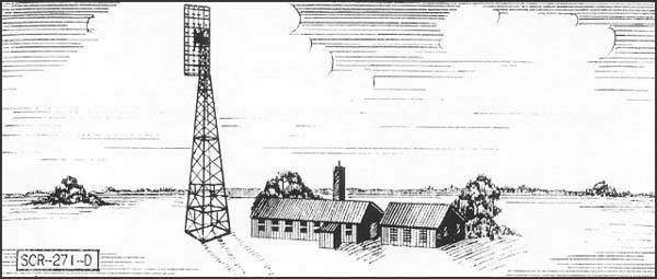
| DESCRIPTION: | Fixed long wave early warning aircraft detector. Azimuth and range supplied on "A" scopes. 271-D has a 100' tower; 271-E, a 50' tower. | |||||||||||||||
|---|---|---|---|---|---|---|---|---|---|---|---|---|---|---|---|---|
| USES: | To establish a screen of warning which gives data on aircraft as early as possible, but with a sacrifice of accuracy in range, azimuth and elevation. IFF equipment RC-151 is used. | |||||||||||||||
| PERFORMANCE AND SITING: |
Maximum range on a single medium bomber flying at indicated altitudes, when set is on a flat sea level site:
Sets should be sited so that the mean antenna height is between 100 and 1000 ft. above an unobstructed flat surface. The 100' tower should be used when it is desired to get additional low coverage, or to insure clearance above surrounding trees or other obstructions. |
|||||||||||||||
| TRANSPORTABILITY: | Sets are packed in 106 units, weighing a total of 42,279 lbs. Largest unit is 176" x 25" x 20". Total volume is 4008 cu. fit. | |||||||||||||||
| INSTALLATION: | Requires a weatherproof building approx. 20' x 40' for housing radar components and a building approx. 20' x 20' for housing the power units and switchboard. A 100 foot tower on concrete footings is required for an SCR-271-D and a 50-ft. tower for an SCR-271-3. Buildings and tower are built by engineers in about 3 weeks. Radar can be installed by five men in about two weeks. | |||||||||||||||
| PERSONNEL: | 7 men are operating crew. For 24 hour operations, about 50 men are required for radar, communication radio, and camp. | |||||||||||||||
| POWER: | 15.3 KW supplied by PE 74, 25 KVA gasoline-driven generator. Consumption is 4 gal. per hour, non-leaded standard commercial gas. |
--37--
[B L A N K]
--38--
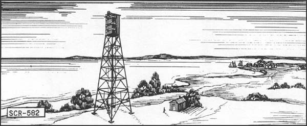
| DESCRIPTION: | Fixed Seacoast Artillery microwave radar. |
|---|---|
| USES: | Gives PPI indication for harbor control and detection of surface craft and low-flying planes. IFF RC-182 is used. |
| PERFORMANCE AND SITING: |
SCR-582 covers 360°. From a height of site of 100 to 125 feet, the reliable maximum range is about 20,000 yards and the most probable maximum range is about 35,000 yards. Occasionally, ranges up to the 90,000-yard limit of the range scale can be obtained. Minimum range is about 1000 yards. Azimuth accuracy is of the order of ± 2° depending somewhat on the range scale in use. the range accuracy may be considered ± 3 per cent of the range scale in use. The range scales are 10,000, 30,000, and 90,000 yards. Set should be sited not less than 30 feet above the surrounding terrain and at least 100 to 150 feet above sea level. Optimum height of site is between 150 and 500 feet. Site should not include within the arc of surveillance any obstructions which would come within 5 to 10 degrees of the antenna axis. |
| TRANSPORTABILITY: | Shipment includes spares and separate generator. Complete shipment is packed in 41 units, including power unit and power house. Largest package (power unit) is 5'9" x 6' x 5'11" and weighs 2060 lbs. |
| INSTALLATION: | Set normally is installed in existing harbor defense or group observation posts by Signal Corps personnel. No tower or buildings are furnished as part of the set, but power plant shelters are obtainable. |
| PERSONNEL: | SCR-582 requires one man to operate the set and another to plot the position of detected targets. These men relieve each other every thirty minutes. A power plant operator and maintenance man must be available. For 24-hour operation a chief of section, five operators, two power plant operators, and one maintenance man are required. |
| POWER: | Requires about 1.8 KW, 110 V, 60 cycles, single phase. |
--40--
* SCR-682 Transportable Microwave Seacoast Artillery Set
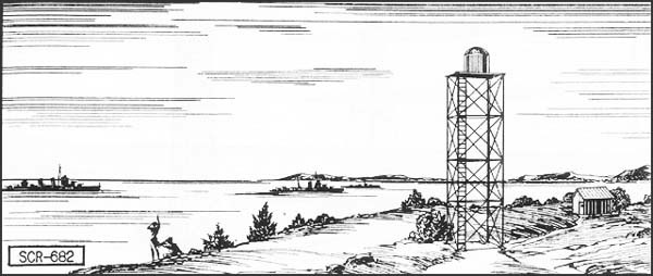
| DESCRIPTION: | Transportable Seacoast Artillery microwave radar. |
|---|---|
| USES: | Used by 155-mm and 8-inch railway battalions. PPI gives indication of surface craft and low-flying planes. Uses IFF RC-282. |
| PERFORMANCE AND SITING: |
Set covers 360°. For a height of 100 feet, range will average 50,000 yards or greater. At times, under favorable conditions, very much greater maximum ranges will be achieved from sufficient heights of site. Minimum range is about 500 yards. Azimuth accuracy is on the order of ± 2 degrees depending somewhat on the range scale in use. The range accuracy thus may be considered ± 3 per cent of the range scale in use. The range scales are 10,000; 4,000p; 160,000; and 320,000 yards. Set should be sited not less than thirty feet above the surrounding terrain and preferably at least 100 feet above sea level. The optimum height of site is between 150 and 500 feet. |
| TRANSPORTABILITY: | A transportable version of the SCR-582, SCR-682 can be carried in two standard 21/2-ton 6x6 cargo trucks. |
| INSTALLATION: | Set normally is operated form a portable tower furnished with set. The operating components are located near the tower in a Shelter HO-17 or housing constructed by the using troops from materials obtained locally. No transportation is furnished with the set. |
| PERSONNEL: | One man operates the set and another plots the position of detected targets. These men relieve one another every thirty minutes to reduce fatigue. For 24-hour operation a chief of section, five operators, two power plant operators, and one maintenance man are required. |
| POWER: | Requires about 1.28 KW, 120 V, 60 cycles, single phase. |
* Available for issue in latter part of 1943.
--41--
SCR-296-A Fixed Medium Wave Coast Artillery Fire Control Set
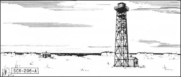
| DESCRIPTION: | Fixed Coast Artillery gun-laying medium wave radar, assigned to modern 6 inch or larger batteries. |
|---|---|
| USES: | Set is designed to track a surface target in range and azimuth. Data are sent to the plotting room and used in firing. An SCR-296-A normally is assigned to one battery, but may furnish data to more. Works with IFF RC-136-A. |
| PERFORMANCE AND SITING: |
Range is shown on "A" scope. The target is tracked in azimuth with a pip matching oscilloscope or a zero-center meter. Range accuracy is about ± 30 yards while azimuth accuracy is about ± 0.20 degree under the best conditions. The set has a dependable range of 20,000 yards on a destroyer size target when employed at a height of 145 feet. Site should be not less than 100 feet above sea level; 150 to 500 feet is recommended. |
| TRANSPORTABILITY: | Shipment includes areas and separate generator. When crated the total weight is 91,763 lbs. Largest unit is 5,270 lbs. |
| INSTALLATION: | SCR-296-A includes a tower, an operating building, and two power plant buildings. The tower is obtainable in heights of 25, 50, 75, and 100 feet. Concrete floors must be put in locally. |
| PERSONNEL: | Operating crew consists of 5 men in addition to a power plant operator and maintenance man who should be available at all times. |
| POWER: | Primary power of 2.3 KW is supplied by PE-84C -- commercial or auxiliary 110 V, AC single phase. Generator needs high octane gas. |
--42--
*Mark 16 Mobile Microwave Search and Fire Control Set
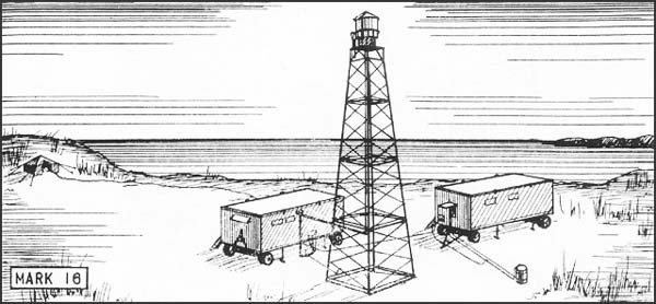
| DESCRIPTION: | Microwave surface search and fire control for mobile sea coast artillery. |
|---|---|
| USES: | Supplies gun-laying information in range and azimuth to plotting board, and works with 155-mm., 5", 6", and 7" guns. Indication is given on "A" and PPI scopes. set has provision for IFF identification connections. |
| PERFORMANCE: | Reliable maximum range on large ships, for 50' antenna height, is 15 miles; reliable minimum range is 400 yds. Range accuracy ± 25 yds. Azimuth accuracy, ± 1/4°. |
| TRANSPORTABILITY: | Shipment includes spares, testing equipment and separate generator. Total weight of shipment, including trailers, is about 14 tons. Can be carried in any ship hold exceeding 8' x 11' x 20'. |
| INSTALLATION: | Set is carried in two trailers. Power unit and dismantled antenna and tower are carried in one; all other components are carried in the other. The trailers are usually hauled by caterpillar tractors. |
| PERSONNEL: | Two operators and one maintenance man are minimum requirement. For 24-hour operation, 6 operators are required. |
| POWER: | Primary power required: 115 V AC, 60 cycle power, 5 KVA. Gas driven generator requires auto type gasoline. |
* Available for issue in latter part of 1943.
--43--
[B L A N K]
--44--
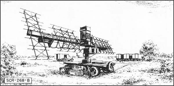
| DESCRIPTION: | Mobile medium-range long-wave searchlight control, AAAIS, and substitute gun-laying equipment. SCR-268 consists of two trailers; SCR-268-B, of a trailer and 4 trucks, Uses IFF RC-148. |
|---|---|
| USES: | To search for targets and furnish position data for AAAIS. Transmits present azimuth and angular height to searchlight control station for directing searchlight. Transmits present azimuth, angular height and altitude to M-4, M-7, or M-9 directors for gun-laying. |
| PERFORMANCE AND SITING: |
Reliable maximum range, 50,000 yds. Minimum range, 3000 yds. With set carefully oriented and aligned, average errors are as follows: altitude, 100 yds; azimuth, 10 mils; angular height (above 350 mils), 10 mils. Orientation and alignment are complex, and must be checked daily. For best results, set should be located on high ground, level for 100 yds. roundabout. |
| TRANSPORTABILITY: | Equipment is carried in vehicles. Total weight of SCR-268 is 15 tons. Largest vehicle weighs 9 tons and measures 8' x 102/3' x 18'. total weight of SCR-268-B is 42.6 tons. Largest vehicle weighs 14 tons and measures 81/3' x 11' x 243/4'. |
| INSTALLATION: | Thirteen men can install set and obtain approximate data in 2 hrs. Accurate orientation and alignment take 4 more hours. |
| PERSONNEL: | Minimum of 5 operators and a Chief Radar Operator are required. |
| POWER: | 9 KVA, 120 V, 50-60 cycles AC required. Source is generator (supplied with set). Unleaded gasoline should be used when possible. Consumption is 3 to 4 gal. per hour. Modification kit PE-178 permits operation on commercial power. |
--46--
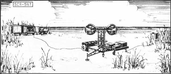
| DESCRIPTION: | Mobile microwave radar-optical height finder. (Slant range supplied by radar; azimuth and angular height by optical tracking.) Set consists of antenna trailer, tractor, and spare parts truck. Early models also include a power van. |
|---|---|
| USES: | To supply slant range or altitude to Antiaircraft Artillery fire control instruments. |
| PERFORMANCE AND SITING: |
Maximum range (limited by data transmission system), 25,000 yds. Useful range is generally limited by visibility. Minimum range, 300 yds. Average range error, ± 25 yds. Altitude limits, 300 to 10,000 yds. Set should be sited for maximum visibility. |
| TRANSPORTABILITY: | Set is transported in vehicles, the largest of which weighs 7.7 tons and measures 8' x 10' x 211/2'. Total weight of set without power van is 16.6 tons; with power van, 24.3 tons. |
| INSTALLATION: | Five trained men can set up and synchronize the equipment with associated director in 20 minutes. |
| PERSONNEL: | Three operators and a chief radar Operator are minimum requirement. When power van is used, additional personnel is needed. |
| POWER: | Early models use power from van-mounted engine-driven generator, consuming 1 gal. gas per hour. Later models receive power from Antiaircraft Gun Battery power plant, the peak power required being about 3.5 KVA, single phase. |
--48--
SCR-545 Mobile Long Wave Aircraft Search and Microwave AA Fire Control Set
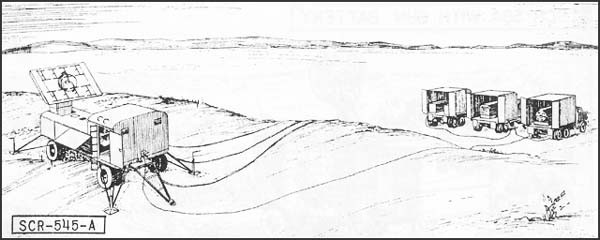
| DESCRIPTION: | Mobile long wave aircraft search and microwave AA gun-laying. Set consists of trailer and prime-mover carrying power plant. One spare parts truck furnished for each antiaircraft gun battalion. Provides present azimuth, angular height, and slant range. Operates with IFF equipment RC-145. |
|---|---|
| USES: | To search for targets and furnish position data for AAAIS. Transmits necessary present position data for all antiaircraft gun directors. May also be used as radar range-finder, with separate visual determination of azimuth and angular height. |
| PERFORMANCE AND SITING: |
Maximum reliable range, 50,000 yds. Minimum range, 500 yds. Average range error, 25 yds. Average azimuth and angular height error, 3 mils. If no interference exists, set should be sited for maximum visibility. |
| TRANSPORTABILITY: | Set is carried in vehicles. Excluding spare parts truck they weigh a total of 27 tons, and occupy 3840 cu. ft. Largest vehicle measures 81/3' x 101/4' x 243/4'. Spare parts truck (supplied with every 4 sets) weighs 8 tons. |
| INSTALLATION: | Operates from vehicles in which mounted. SCR-545 can be set up, oriented, and synchronized with associated equipment in 1 hour, using a crew of 9 trained men. |
| PERSONNEL: | Four operators and a chief Radar Operator are minimum requirement. |
| POWER: | Peak power required is approximately 15 KVA. Supplied by gasoline engine driven generator, consuming 5 gal. per hour. |
--49--
SCR-584 Mobile Microwave Anti-Aircraft Fire Control Set
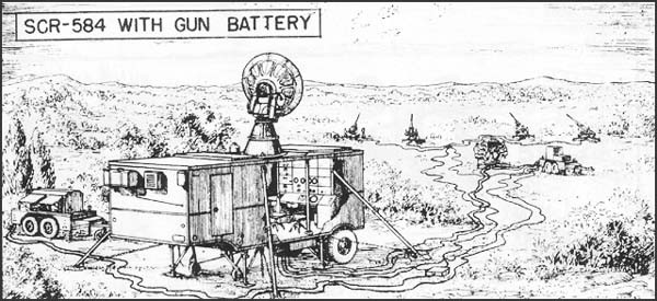
| DESCRIPTION: | Mobile medium-range microwave Antiaircraft Artillery gun-laying set, consisting of semi-trailer and 4-ton tractor. One spare parts truck is furnished to each AA gun battery. Supplies present azimuth, angular height and slant range or altitude. Operates with IFF equipment RC-184. |
|---|---|
| USES: | To search for targets and furnish position data for AAAIS. Transmits necessary present position data for all long-range AA gun directors. May also be used as radar range or height finder with separate visual determination of azimuth and angular height. |
| PERFORMANCE AND SITING: |
Maximum reliable range, 50,000 yds. Minimum range, 500 yds. Average range error, 25 yds. Average azimuth and angular height error, 3 mils. Set should be located for maximum visibility. |
| TRANSPORTABILITY: | Set is transported in vehicles. Excluding spare parts truck, set weighs a total of 15 tons and occupies 2770 cu. ft. Largest vehicle measures 8' x 101/2' x 191/2'. Spare parts truck (supplied with every 4 sets) weighs 7 tons. |
| INSTALLATION: | SCR-584 can be set up, oriented and synchronized with associated equipment in 30 minutes, using crew of 9 trained men. |
| PERSONNEL: | Two operators and Chief Radar Operator are minimum requirement. |
| POWER: | Required peak power of about 12 KVA, 3 phase, is supplied by Gun Battery power plant. |
--50--
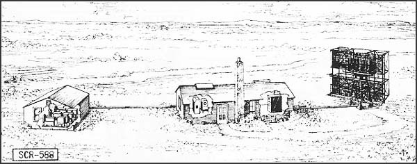
| DESCRIPTION: | Fixed medium-range, long wave aircraft detector and GCI. Provides azimuth, range, and altitude data. Type HR and PPI scopes. | ||||||||||||||||||||
|---|---|---|---|---|---|---|---|---|---|---|---|---|---|---|---|---|---|---|---|---|---|
| USES: | To give continuous plan position and accurate relative height of enemy plane and friendly fighter plane for GCI. Set can also be used for early warning and to give increased coverage at low angles of search. IFF equipment RC-188 is used. When operating as GCI, VHF equipment SCR-624 is required. | ||||||||||||||||||||
| PERFORMANCE AND SITING: |
|
||||||||||||||||||||
| TRANSPORTABILITY: | Set is packaged for shipment in 55 units, weighing a total of 54,000 lbs. Largest unit measures 15.3' x 3.8' x 1.8'. Total shipping space is 3500 cu. ft. | ||||||||||||||||||||
| INSTALLATION: | Requires a weatherproof building approximately 20' x 40' for housing radar components and a building approximately 20' x 20' for power units and switchboard. A 25' tower on concrete footing is required for support of antenna. Buildings and tower can be built by Engineers in about 3 weeks. Radar can be installed by 5 men in 2 weeks. | ||||||||||||||||||||
| PERSONNEL: | 8 men are operating crew. For 24-hour operation about 54 men are required to run radar, communication radio, and camp. | ||||||||||||||||||||
| POWER: | 4 KW at 230 volts and 1 KW at 115 volts, from three PE-198 electric diesel units, supplied with set. (Two units operate simultaneously). Fuel consumption is 21/2 gals. of Diesel fuel oil per hour. | ||||||||||||||||||||
--52--
SCR-527 Mobile Long Wave Aircraft detector and GCI
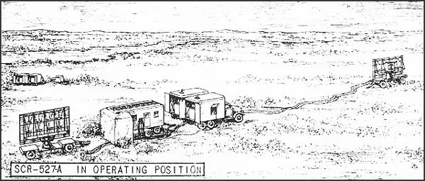
| DESCRIPTION: | Seven-truck mobile long wave medium-range aircraft detector and GCI. Gives azimuth, range and altitude on PPI and HR scopes. | ||||||||||||||||||||
|---|---|---|---|---|---|---|---|---|---|---|---|---|---|---|---|---|---|---|---|---|---|
| USES: | To provide necessary continuous plan position and accurate relative height of enemy plane and friendly fighter plane for GCI. Set can also be used for early warning and to give increased coverage at low angles of search. IFF equipment RC-127 is used. When operating as a GCI station, VHF equipment SCR-624 is required. | ||||||||||||||||||||
| PERFORMANCE AND SITING: |
Maximum range on a single medium bomber flying at indicated altitudes when set is installed on a flat sea level site:
When operating as GCI, set must be sited so that a flat unobstructed reflecting surface extends at least 1/4th mile in the sector in which height-finding is desired. Good GCI sites are extremely rare, and workable sits are found only with difficulty. When used for early warning, these sets should be sited at a height between 100 and 1,000 feet above an unobstructed reflecting surface. |
||||||||||||||||||||
| INSTALLATION: | Operates from trucks in which mounted. Can be placed in operation in approximately 6 hours after arrival at proper site. | ||||||||||||||||||||
| TRANSPORTABILITY: | Set consists of 7 vehicles weighing a total of 97,610 lbs. Largest vehicle measures 26'21/2" x 8'11/2" x 10'. | ||||||||||||||||||||
| PERSONNEL: | 8 men are operating crew. For 24-hour operations, about 54 men are required for operation of radar, communication radio, and camp. | ||||||||||||||||||||
| POWER: | Supplied by two PE 137-A 25 KW, 120/208 V gasoline generators, one of which serves as a spare. Supplied with set in separate trucks. Fuel consumption is 2.4 gal. per hour of non-leaded standard commercial gasoline. | ||||||||||||||||||||
--53--
SCR-615-A and SCR-615-B Microwave Aircraft Detectors for GCI
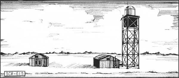
| DESCRIPTION: | Fixed, microwave aircraft detector for GCI. Gives range, altitude and azimuth data on planes. Has 2 "A" scopes, one PPI. | |||||||||||||||
|---|---|---|---|---|---|---|---|---|---|---|---|---|---|---|---|---|
| USES: | Adjunct to a search radar to give accurate height data, thus permitting GCI operation from sites not suitable for other GCI sets which need flat sites. Also gives low-angle coverage when operated as search set. IFF equipment RC-215 is used. | |||||||||||||||
| PERFORMANCE AND SITING: |
Range on a single, medium bomber flying at indicated altitudes:
For low angle early warning, set is sited as high as possible in coastal areas overlooking sea. When sited overlooking land, the site should be as high as possible. Back radiation is negligible. |
|||||||||||||||
| TRANSPORTABILITY: | When packed for shipment by freight the total weight is expected to be approximately 10,000 lbs. | |||||||||||||||
| INSTALLATION: | Antenna and transmitting and receiving components are installed on a wooden tower 30', 55', or 105' high, depending on site. Operating controls and presentation unit are installed in a separate weatherproof building approximately 20' x 20'. If used as adjunct to a search type set, controls and presentation can be installed in same building with search set equipment. A 20' x 20' building is required for power units and switchboard. Tower and buildings must be built by engineers and require approx. 2 weeks. Radar components can then be installed by 5 men in about 5 to 6 days. | |||||||||||||||
| PERSONNEL: | 8 men comprise an operating crew. For 24-hour operation about 54 men are required to operate radar, communication radio and camp. | |||||||||||||||
| POWER: | 12 KW, 120/208 V 3 phase supplied by electric diesel generator. |
--54--
*SCR-627 Long wave GCI
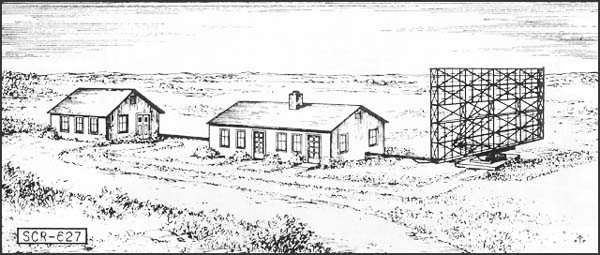
| DESCRIPTION: | Fixed, long wave medium-range GCI that supplies azimuth, altitude, and range data on planes. Two PPI and one HR scope supplied. | |||||||||||||||
|---|---|---|---|---|---|---|---|---|---|---|---|---|---|---|---|---|
| USES: | To provide continuous plan position and accurate relative height of enemy plane and friendly fighter plane for GCI. Set can also be used for early warning and to give increased coverage at low angles of search. IFF equipment RC-207 is used with this set. When operating as a GCI station, VHF communication equipment SCR-624 is required. | |||||||||||||||
| PERFORMANCE AND SITING: |
Maximum range on a single medium bomber flying at indicated altitude, when set is installed on a flat sea-level site:
|
|||||||||||||||
| TRANSPORTABILITY: | Set when crated is expected to weigh about 75,000 lbs. | |||||||||||||||
| INSTALLATION: | Requires a weatherproof building about 20' x 40' for housing radar components, and a building 20' x 20' for the power units and switchboard. Antenna structure is approximately 30' L x 30' H x 20' D and mounts on turning gear installed in a concrete pit approx. 11' x 11' x 7' D. Buildings and tower must be built by engineers in about 3 weeks. Radar components can be installed by 5 men in about 3 or 4 days. | |||||||||||||||
| PERSONNEL: | 8 men comprise an operating crew. For 24-hour operation about 54 men are required to run radar, communication radio, and camp. | |||||||||||||||
| POWER: | Power is supplied by two PE-137 A, 25 KW, 120/208 volt gasoline generator sets (one spare). Fuel consumption is 2.4 gal. per hour, and non-leaded standard commercial gasoline is needed. | |||||||||||||||
* Available for issue in latter part of 1943.
--55--
*SM Microwave Shipborne CG Set
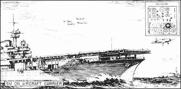
| DESCRIPTION AND USES: | Microwave set with three axis stabilized antenna, installed on aircraft carriers to search for enemy planes, particularly low-flying and shadow planes, and to supply height, speed and course data so that a Fighter Director Officer can direct fighters to an interception. Can also be used to search for ships and periscopes. SM is correlated with search sets, such as SK, and with radio communication to planes. Has provisions for A and G band IFF, and a built-in BO antenna. For night interception, AIA is required in planes. |
|---|---|
| PERFORMANCE: | SM has a reliable detection range of 35 miles on a medium bomber 500 ft. above optical horizon. surfaced submarines can be followed to horizon. Periscopes can be seen 6 miles or more, and buoys can be seen up to horizon. Range can be determined to ± 200 yds., or 1/4%, whichever is greater. Bearing can be determined to ± 1/2°. Elevation can be determined to ±1/3° if airplane is 21/2° or more above optical horizon. If plane is lower, data is less reliable. Accuracy of range difference between two targets is ± 50 yds. for separation of 500-10,000 yds. Elevation limit is 90°. |
| TRANSPORTABILITY: | Spares, testing equipment and separate generator supplied. |
| INSTALLATION: | SM has 23 components weighing a total of about 9 tons. Largest unit is the antenna mount -- 131" high, with a diameter of 67" at base, and weighing about 4,600 lbs. The antenna is 6 ft. in diameter; 8-foot antennas will be installed on later sets. The console (76" x 65" x 24" -- 1,800-2,000 lbs.) splits into 3 parts for installation. |
| PERSONNEL: | Minimum operators per shift required are two, plus one assistant radar officer. Recommended personnel: 15 per day. |
| POWER: | Power required is 45-65 KW, 440 V. 3-phase 60 cycle, supplied by motor generator set, or, in emergencies, from ship's supply. |
* Available for issue in latter part of 1943.
--56--
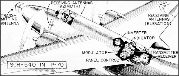
| DESCRIPTION AND USES: |
The SCR-540 is a long wave AI equipment designed from the British AI Mark IV. Two "A" type indicators are used, one for azimuth and one for elevation. External antennas provide azimuth and elevation sensing. IFF signals displayed directly on the scope. SCR-540 operates with the SCR-640 racon. Test set IE-30 is required for maintenance. |
|---|---|
| PERFORMANCE | Maximum beacon range: 100 miles. Maximum search range, 17,000 to 20,000 ft. Minimum range, 300 to 500 ft. Range accuracy, ± 10%. Azimuth limits, 70° forward on either side of line of flight. (No targets detected at ranges greater than plane's altitude.) Azimuth accuracy: right or left indication only when target is more than 5° from line of flight. Within 5° of line of flight, target will show as straight ahead. Elevation limits (at 20,000' altitude), ± 20° from forward line of flight. Elevation accuracy, same as azimuth accuracy. |
| TRANSPORTABILITY: | Set is packaged in 7 units weighing about 225 lbs. Largest package measures 13" x 6" x 26" and weighs 32 lbs. Set is air transportable in any cargo plane. |
| INSTALLATION: | Set is installed in P-70, Beaufighters, and A-20's. Installed weight is about 210 lbs. |
| PERSONNEL: | One radar operator and one maintenance man are minimum requirement. |
| POWER: | Primary power required: 40 amperes at 27.5 volts from plane's DC supply. |
--58--
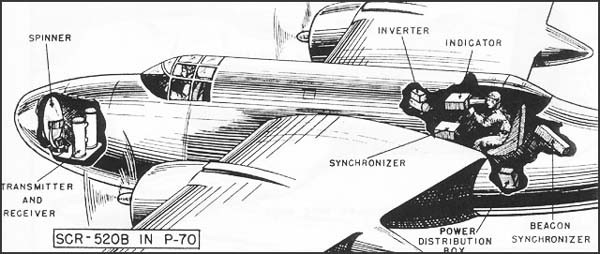
SCR-520-B and SCR-720-A Microwave AI Sets
| DESCRIPTION AND USES: |
The SCR-520-B is a microwave AI equipment scanning the forward 180°. B and C indication is provided for the operator; C indication only for the pilot. In addition, the pilot has a range indicator varied by the operator. Maximum ranges are 3, 10, and 100 statue miles. The SCR-720-A is a small package version of the SCR-520-B. Sets have provisions for IFF identification connections. Both sets work with SCR-620 racon. Test sets IE-30, IE-57, or LZ and PE-143 power equipment are required for maintenance. |
|---|---|
| PERFORMANCE: | Maximum range on racon, 100 miles. Maximum range on P-38, 4 miles; on P-70, 5 miles; on PBY, 7 miles. Minimum range, 250 ft. Azimuth limits, 180° forward. Azimuth accuracy ± 3°. Elevation limits, -10° to +65°. Elevation accuracy, ± 2°. |
| TRANSPORTABILITY: | SCR-520-B is packed in 6 units, the largest of which weighs 180 lbs. and measures 28" x 29" x 40". Total weight: 850 lbs. |
| INSTALLATION: | The SCR-520-B is installed in P-70's. Total installed weight is approximately 600 lbs. The spinner, transmitter and modulator are mounted in the nose. The SCR-720-A will be installed in P-61 airplanes. Installed weight is about 412 lbs. |
| PERSONNEL: | One radar operator and one maintenance man per set are minimum requirement. |
| POWER: | Primary power required: 125 amperes at 27.5 volts from plane's DC supply. |
--59--
AIA Microwave Set for Single-Seated Fighters
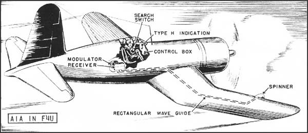
| DESCRIPTION: | Airborne interception set for single-seated nightfighters. |
|---|---|
| USES: | Used to detect and intercept enemy aircraft in fleet operations and in attacks against fixed bases. Designed to work in connection with SM or any GCI set, and has provisions for operating with AN/CPN-6 racon, and for IFF identification connections. Provides range, bearing and relative elevation data, and b, modified H or G indications, all appearing on a single scope. |
| PERFORMANCE: | Detects plane at maximum reliable range of 3 miles and tracks target to 360 ft. Range accuracy is ± 10% on racon, ± 5% in tracking, and ± 25 yds. in gun-laying. Covers ± 60° forward in bearing and elevation. Bearing accuracy is ± 3° on racon, ± 1/2° in gun-laying. Elevation accuracy is ± 3°. |
| TRANSPORTABILITY: | Packaging for shipment is not yet standardized, but total package weight should not exceed 350 lbs. |
| INSTALLATION: | Installed in F4U-2 and F6F-3. In F4U-2, installation weighs 310 lbs., requires removal of two machine guns, and reduces plane's top speed by 2 mph. Installation has no effect on armament or speed of F6F-3. |
| PERSONNEL: | Set is operated by pilot. One maintenance man per set is required. |
| POWER: | Total primary power required: (a) form combination AC-DC primary generator (NEA-3 or NEA-5) -- 30 amps., 27.5 V, DC and 1050 watts, 115 V, 400-2400 cycles AC; or (b) from primary DC generator, requiring use of motor-alternator (800-1-B) -- 91 amps., 27.5 V DC. |
--60--
Lightweight Aircraft Warning Sets
--61--
SCR-602-A & SCR-602-T8 Light Transportable Aircraft Detectors
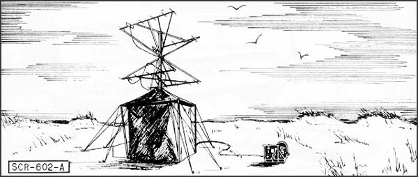
| DESCRIPTION: | Light transportable, long wave medium-range early warning aircraft detector. Azimuth and range supplied on HR and PPI scopes. | ||||||||||
|---|---|---|---|---|---|---|---|---|---|---|---|
| USES: | To provide early warning of aircraft in assault operations from beachheads, isolated installation, captured air bases, etc. Provides limited warning until heavier, longer-range and more accurate equipment can be installed. Is not designed to operate continuously for more than 500 hours without a complete overhaul and replacement of major components. IFF equipment RC-192 is used. | ||||||||||
| PERFORMANCE AND SITING: |
Maximum range on a single medium bomber flying at indicated altitudes when set is on a flat sea level site:
Set should be installed on a flat unobstructed site to obtain maximum coverage of high-flying planes. If set must be used in mountainous terrain, it should be sited so as to employ natural screening of nearby hills and ridges to prevent permanent echoes on scope. |
||||||||||
| TRANSPORTABILITY: | Packed in 9 units, weighing a total of 1875 lbs. (for air transport) or 3450 (for export.) Largest unit: 98" x 14" x 313/4". Total shipping space is 331 cu. ft. | ||||||||||
| INSTALLATION: | Operates in a small lightweight tent, and can be set up for operation in 2 hours. For special requirements a small prefabricated building is available to replace tent. | ||||||||||
| PERSONNEL: | 4 men are required for an operating crew. During an assault operation when set must be operated 24 hours per day, a crew of 14 men is required. This crew should be relieved after 2 to 3 weeks. | ||||||||||
| POWER: | Supplied by dual 600 watt 1200 cycle AC generators and 500 watt DC generator driven by 6 h.p. gasoline engine. Fuel consumption is 1/2 gal. per hour non-leaded standard commercial gasoline. |
--62--
*AN/TPS-1 (SCR-603-T3) Light Transportable Aircraft Detector
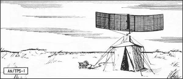
| DESCRIPTION: | Light transportable, medium-wave early warning aircraft detector. Azimuth and range data supplied on "A" and PPI scopes. | ||||||||||
|---|---|---|---|---|---|---|---|---|---|---|---|
| USES: | To provide early warning of approaching aircraft in assault operations from such points as beachheads, isolated installations and captured air bases. Provides limited warning until heavier, longer-range and more accurate equipment can be installed. (Is not designed to operate continuously for more than 2000 hours without a complete overhaul and replacement of major components.) IFF equipment RC-192 is used. | ||||||||||
| PERFORMANCE AND SITING: |
Maximum range on a single medium bomber flying at indicated altitudes when set is on a flat sea level site:
Set should be installed on a flat unobstructed site to obtain maximum coverage of high-flying planes. If set must be used in mountainous terrain, it should be sited so as to employ natural screening of nearby hills. For best operation, terrain should be clear of any heavy tree clusters for 1000'. |
||||||||||
| TRANSPORTABILITY: | Set is packed for shipment in 8 units weighing a total of 1145 lbs. for air transport) or 1500 lbs. (for export). Total shipping space is 85 cu. ft. | ||||||||||
| INSTALLATION: | Equipment operates in a small light-weight tent, and can be set up for operation in 2 hours. | ||||||||||
| PERSONNEL: | 4 men required for operating crew. During an assault operation when set must be operated 24 hours a day, a crew of 14 men is required. This crew should be relieved after 2 to 3 weeks. | ||||||||||
| POWER: | 115 v. single phase 400 cycle AC, plus 28 v. DC, supplied by 1300 watt AC and 25 watt DC gasoline-driven generators. Fuel consumption is 1/2 gal. per hour, non-leaded standard gasoline. |
* Available for issue in latter part of 1943.
--63--
*AN/TPS-3 (SCR-602-T8) Light Transportable Aircraft Detector
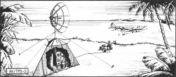
| DESCRIPTION: | Light transportable, medium wave, medium-range early warning aircraft detector. Azimuth and range data supplied on "A" and PPI scopes. | ||||||||||
|---|---|---|---|---|---|---|---|---|---|---|---|
| USES: | To provide early warning of aircraft in assault operations from beachheads, isolated installations, captured air bases, etc. Provides limited warning until heavier, longer range and more accurate equipment can be installed. (Is not designed to operate continuously for more than 1000 hours without a complete overhaul and replacement of major components.) IFF equipment RC-192 is used. | ||||||||||
| PERFORMANCE AND SITING: |
Maximum range on a single medium bomber flying at indicated altitudes when set is on a flat sea level site:
Set should be installed on a flat, unobstructed site to obtain maximum coverage of high-flying planes. If used in mountainous terrain, it should be sited to employ natural screening of nearby hills. |
||||||||||
| TRANSPORTABILITY: | Set is packed in 4 units, weighing a total of 600 lbs. (for air shipment) or 700 lbs. (for export). Total shipping space is 40 cu. ft. | ||||||||||
| INSTALLATION: | Equipment operates in a small light-weight tent and can be set up for operation in 3 or 4 hours. | ||||||||||
| PERSONNEL: | 4 men are required for an operating crew. During an assault operation when set must be operated 24 hours per day, a crew of 14 men is required. This size crew cannot carry on longer than 2 to 3 weeks under these conditions and must be relieved at that time. | ||||||||||
| POWER: | 115 V single phase 400 cycle AC plus 24 V DC, supplied by 1300 watt AC and 250 watt DC gasoline-driven generator. Fuel consumption is 1/2 gal. per hour, non-leaded standard gasoline. |
* Available for issue in latter part of 1943.
--64--
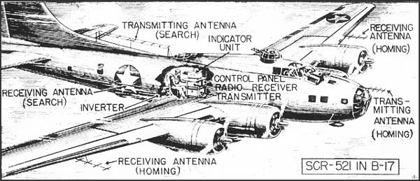
| DESCRIPTION: | Airborne long-wave search set for patrol bombers. Range and left-right indication are provided on an ASV scope. IFF identification signals are displayed directly on the scope. These sets are no longer in production. |
|---|---|
| USES: | For locating and homing on craft or coastal targets, and for navigating. Sets work with SCR-621 or YH racon. |
| PERFORMANCE: | Reliable maximum ranges: surfaced submarines (broadside), 6 miles; 4,000-8,000 ton ship, 25 miles; well-defined coastline, 60 miles. Minimum range is 350 yds. Range accuracy, ± 10%. Sets cover forward 150° when searching, 40° when homing on a target. Bearing accuracy in homing is ± 2° to ± 5°. |
| TRANSPORTABILITY: | Sets are packed in 7 units for shipment, weighing a total of 300 lbs. Largest package is 16" x 21" x 24" and weighs 78 lbs. |
| INSTALLATION: | SCR-521's are installed in B-17, B-24, B-25 and B-34 planes. ASVC and ASE are installed in B-17, B-24, PBY5, PBY5A, and PBN. The external antennas reduce plane's top speed by about 5 to 7 knots, and the forward nose antenna interferes with the firing of the forward flexible guns. (The addition of a polyplexer in future installations will eliminate the nose antenna). |
| PERSONNEL: | Army requires one operator and one maintenance man per set. Navy requires one operator per set and 4 maintenance men per squadron. |
| POWER: | Total primary power required: (a) from combined AC-DC generator -- 2.6 amps., 27.5 v. DC and 500 watts, 115 v., 800-2400 cycles AC; or (b) from primary DC generator, requiring use of motor-alternator -- 39 amps., 27.5 v. DC. |
--66--
ASA Medium Wave ASV Set
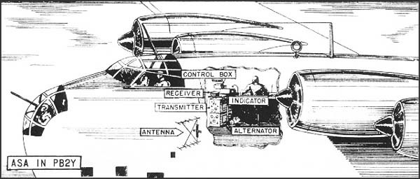
| DESCRIPTION: | Medium-wave airborne search set designed for installation in large patrol bombers. Provides range and right-left indication on ASV scope. Includes provisions for altimeter to 20,000 feet. (This set is no longer in production). |
|---|---|
| USES: | For locating and homing on surface craft or coastal cities beyond visual range, and for navigating. A modification kit is available for IFF identification provision. |
| PERFORMANCE: | Reliable maximum ranges: surfaced submarine (broadside), 10 miles; 4,000-8,000 ton ship, 35 miles; well-defined coastline, 60 miles. Minimum range is 350 yards. Range accuracy is ± 5%. Covers 180° in bearing when searching and 40° when homing. Bearing accuracy in homing is from ± 2° to ± 5°. |
| TRANSPORTABILITY: | Packed in 5 units for shipment, including spares for 200 hours operation, and weighing a total of 569 lbs. Largest package measures 35" x 27" x 291/2" and weighs 223 lbs. |
| INSTALLATION: | Installed chiefly in PB2Y-3's, adding about 353 lbs. to plane's weight and reducing its top speed by 4 to 5 knots. |
| PERSONNEL: | One operator per set and 4 maintenance men per squadron are required. In normal operations, the operator is relieved by other members of the crew. |
| POWER: | Total primary power required is 78 amps., 27.5 V from plane's DC supply. |
--67--
ASB & "ASB Series" Medium Wave ASV Sets
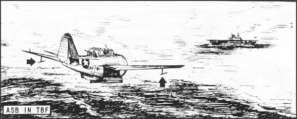
| DESCRIPTION: | Airborne medium-wave search sets for carrier-based planes and flying boats. Provides range and right-left indication on an ASV scope. There are eight models of ASB. Corresponding components of each model are interchangeable. "ASB Series" is an improved transmitter and receiver, used as replacement in any ASB set. |
|---|---|
| USES: | For locating and homing on surface craft and coastal cities, for assistance in night bombing and torpedo attacks, and for navigating. All sets have provisions for IFF and YJ racon response. |
| PERFORMANCE: | Reliable maximum ranges: surface submarine (broadside), 8 miles; 4,000-8,000 ton ship, 25 miles; well-defined coastline, 60 miles. "ASB Series" extends these ranges to 15 miles on surfaced submarine, 25-35 miles on 5,000-ton ship, and 70 miles on coastline. Minimum range is 350 yards. Range accuracy, ± 10%. Covers 180° in bearing when searching, and 40° when homing on target. Bearing can be estimated to about ± 3°, when homing. |
| TRANSPORTABILITY: | ASB-4 and ASB-8 are packed in 2 units for shipment, weighing a total of 171 lbs. Other models are packed in one unit, weighing 240 lbs. and measuring 37" x 42" x 311/2". Package includes operating spares for 200 hours. Crated "ASB Series" will be a smaller package. |
| INSTALLATION: | Installed in SBD, SO3C, TBF, SB2 C, PBY-5, PBY-5A, PBN, PB4Y, PV-3. Average weight is 152 lbs. Set cuts plane's top speed by 2 to 5 knots. |
| PERSONNEL: | One operator per set is required, and 12 maintenance men per carrier-based group or 4 per land-based squadron. One operator serves a ten-hour watch, relieved by other members of crew. |
| POWER: | Total primary power required: (a) from combination AC-DC primary generator (NEA-3 or NEA-5) -- 350 watts for ASB 400 watts for "ASB Series", 115 V, 600-1400 cycles AC (plus 85 watts for repeat indicator); or (b) from primary DC generator, requiring use of motor-alternator 9800-1-B) -- 25 amps. for ASB, 30 amps. for "ASB Series", 27.5 V DC. |
--68--
SCR-517-A, SCR-517-B or ASC-1, and SCR-517-C Microwave ASV Sets
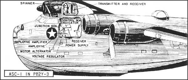
| DESCRIPTION: | Airborne microwave search sets for installation in patrol bombers. Range and azimuth are provided on PPI scope in SCR-517-B or ASC-1, and on B scopes in other models. Sets have provisions for IFF. |
|---|---|
| USES: | For locating and homing on friendly or enemy surface craft or coastal targets and for navigation. All sets except SCR-517-A work with AN/CPN-3 racon. |
| PERFORMANCE: | Maximum reliable ranges: surface submarines (broadside), 18 miles; 4,000-8,000 ton ship, 40 miles; well-defined coastline, 90 miles. Range accuracy, ± 3%. SCR-517-A and SCR-517-C cover 180° forward; SCR-517-B or ASC-1 covers 360°. Azimuth accuracy is ± 3°. |
| TRANSPORTABILITY: | ASC-1 is packaged in 4 units for shipment, weighing a total of 689 lbs. Largest package is 43" x 37" x 25" and weighs 177 lbs. Army sets are packaged in 6 units, weighing a total of 850 lbs. Largest package is 29" x 40" x 28" and weighs 180 lbs. Test set IE-30 (For SCR-517-A and SCR-517-C) or IE-57 or LZ (for SCR-517-B) and PE-143 power equipment are required for maintenance. |
| INSTALLATION: | SCR-517-A and SCR-517-C are installed in B-17, B-18, B-24, B-25, and B-34 planes. Average installed weight is 600 lbs. In B-17 and B-25, the antenna is housed in retractable ventral turret replacing the gun turret. In the B-34, a new opening for antenna housing is cut in the fuselage under the upper gun turret, which can no longer be used. SCR-517-B is installed in B-24. ASC-1 is installed in PB2Y-3, adding about 550 lbs. to plane's weight and reducing its top speed by 2 to 5 knots. |
| PERSONNEL: | One operator and one maintenance man per set are required by Army; Navy requires 4 maintenance men per squadron. |
| POWER: | Total primary power required is 105 amps., 27.5 v., from plane's DC supply. |
--69--
SCR-717-A & SCR-717-B Microwave Small-Package ASV Sets
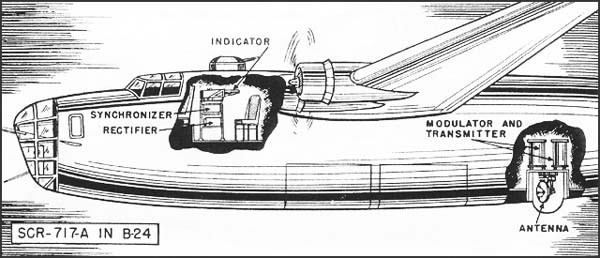
| DESCRIPTION AND USES: |
This is a microwave small package ASV developed from the SCR-517. The SCR-717-A provides B scopes for pilot and operator with maximum ranges of 5, 20, 50, and 100 nautical miles. Either the forward or rear 180° is scanned as desired. The SCR-717-B provides PPI scopes for pilot and operator with maximum ranges of 4, 25, 40, and 100 nautical miles. 360° scanning is provided on all ranges, with open center indication on the 4 mile range. The sets have provisions for IFF identification connections. Includes connections for operation with IR, racon and AN/APQ-5 (radar bomb-sight) equipment. Test set IE-57 or LZ and PE-143 power equipment are required for maintenance. |
|---|---|
| PERFORMANCE: | Estimated maximum range: 70 miles on 5,000-10,000 ton ships, 20 miles on surfaced submarine. Minimum range 600 ft. |
| TRANSPORTABILITY: | Each set is packaged in 5 units the largest of which measures 24" x 37" x 43" and weighs 177 lbs. Total shipment weighs 773 lbs. and occupies 78 cu. ft. |
| INSTALLATION: | Antenna is installed in a retractable belly turret in the B-24 or B-25 replacing the lower gun turret. Remaining components are installed in radio compartment. Total installed weight including operator's seat and retraction gear is 560 lbs. |
| PERSONNEL: | One radar operator and one maintenance man per set are minimum requirement. |
| POWER: | Primary power required: 100 amperes at 27.5 volts from plane's DC supply. |
--70--
ASD Microwave ASC Set
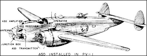
| DESCRIPTION: | Airborne microwave search set for installation on patrol planes. Provides range and bearing on B scopes, furnished to operator and pilot. |
|---|---|
| USES: | For locating and homing on friendly or enemy surface craft or on coastlines; for general navigation; and for bombing of coastal or marine targets. Set has provisions for operating on racon (AN/CPN-6) and IFF connections for identification of targets. ASD can be used with AN/APQ-5 for blind bombing. |
| PERFORMANCE: | Reliable maximum ranges: surfaced submarines (broadside), 16 miles; 4,000-8,000 ton ship, 27 miles; well-defined coastline, 45 miles. Minimum range is 200 yards. Range accuracy, ± 10%. Covers 140° of bearing with accuracy of ± .3°. Elevation limits are from +91/2° to -91/2°. |
| TRANSPORTABILITY: | Packed in 6 units for shipment, including spares for 200 hours operation, and weighing a total of 499 lbs. Largest unit measures 38" x 29" x 16" and weighs 190 lbs. |
| INSTALLATION: | Installed weight in PV-1 is 295 lbs. Effect on plane's speed is negligible. |
| PERSONNEL: | One operator per set and 4 maintenance men per squadron are required. In normal operations, pilot uses his scope to relieve operator. |
| POWER: | Total primary power required: (a) from combination AC-DC primary generator (NEA-3 or NEA-5) -- 7.7 amps., 27.5 V DC and 875 watts, 115 V, 400-2400 cycles AC; or (b) from DC primary generator, requiring use of motor alternator (800-1-B) -- 58 amps., 27.5 V DC. |
--71--
ASG, ASG-1, AN/APS-2a (ASG-2) & AN/APS-2 (ASG-3) Microwave ASV Sets
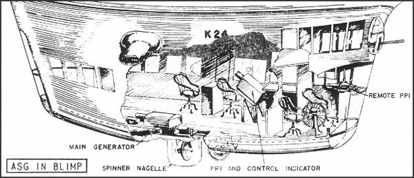
| DESCRIPTION: | Airborne microwave search sets. ASG and AN/APS-2A for blimps, ASG-1 and AN/APS-2 for patrol bombers. PPI scopes give range and bearing. |
|---|---|
| USES: | For locating and homing on surface craft and for general navigation. AN/APS-2 can be used with AN/APO-5 for blind bombing. All sets have provisions for IFF and for racon AN/CPN-3. |
| PERFORMANCE: | Maximum reliable range: surface submarine (broadside), 18 miles; 4,000-8,000 ton ships, 40 miles; well-defined coastline, 90 miles. Minimum range is 400 yards. Range accuracy is ± 7%. Sets cover 360° with bearing accuracy of ± 3°. |
| TRANSPORTABILITY: | ASG is packaged in 5 units for shipment, weighing a total of 741 lbs; ASG-1 in 7 units weighing 764 lbs. Largest package for ASG measures 591/2" x 47" x 29" and weighs 372 lbs.; for ASG-1, 35" x 261/2" x 46" weighing 257 lbs. AN/APS-2A is packaged in 5 units, weighing a total of 764 lbs; AN/APS-2 in 7 units weighing 741 lbs. Largest unit for AN/APS-2A measures 591/2" x 47" x 29" and weighs 372 lbs.; for AN/APS-2, 35" x 261/2" x 46" weighing 257 lbs. |
| INSTALLATION: | ASG and AN/APS-2A are installed in K ships; ASG-1 and AN/APS-2 in PBM-1, PBM-3c, PBJ, and PB4Y patrol bombers. In the PBJ and PB4Y-1, the lower ventral gun turret is removed. Average installed weights are 350 lbs. for ASG and AN/APS-2A, and 360 lbs. for ASG-1 and AN/APS-2. Installations reduce the aircraft's top speed by 2 to 5 knots. |
| PERSONNEL: | One operator per set is required, relieved by other members of the crew. 4 maintenance men are required per squadron. |
| POWER: | Total primary power required: (a) from combination AC-DC primary generator -- 5.2 amps., 27.5 V DC and 850 watts, 115 V, 400-2400 cycles AC; or (b) from DC primary generator, requiring use of motor alternator -- 55.2 amps., 27.5 V DC. |
--72--
*AN/APS-3 (ASD-1) Microwave ASV and Torpedo-Laying Set
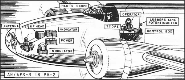
| DESCRIPTION: | Airborne microwave search and torpedo-laying set, for installation on patrol planes or torpedo bombers. Range and bearing are provided on B scopes supplied to operator and pilot. |
|---|---|
| USES: | For locating and homing on friendly or enemy surface craft and coastal targets, for general navigation, and for blind bombing (with AN/APQ-5) and torpedo-laying. Includes provisions for operating on AN/CPN-6 racon and for IFF identification connections. |
| PERFORMANCE: | Maximum reliable ranges: surfaced submarine (broadside), 20 miles; 4,000-8,000 ton ship, 40 miles; well-defined coastline, 80 miles. Minimum range is 200 yards. Range accuracy, ± 1%. Covers 160° in bearing, with accuracy of ± 3°. When 60° of bearing is expanded on scopes for torpedo-laying, accuracy is ± 1°. elevation limits are +9° to -9°. |
| TRANSPORTABILITY: | Packed in 6 units for shipment, including spares for 200 hours operation, and weighing a total of 499 lbs. Largest unit measures 38" x 29" x 16" and weighs 190 lbs. |
| INSTALLATION: | Installed in PV-2, TBM, TBU, PBN and PBY-5, adding about 300 lbs. to plane's weight. Effect on plane's speed is negligible. |
| PERSONNEL: | One operator per set and 4 maintenance men per squadron (or 12 per group on carrier) are required. In normal operations the pilot uses his scope to relieve operator. |
| POWER: | Total primary power required: (a) from combination AC-DC primary generator -- 7.7 amps., 27.5 V DC and 875 watts, 115 V, 400-2400 cycles AC; or (b) from primary DC generator, requiring use of motor-alternator -- 58 amps., 27.5 V DC. |
* Available for issue in latter part of 1943.
--73--
AN/APS-4 (ASH) Lightweight ASV and Interception Set
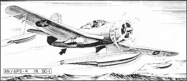
| DESCRIPTION: | Lightweight airborne search and interception set primarily for carrier based aircraft. All major components are contained in a single pressurized housing similar to a Mk 41 depth bomb, and detachable in the same manner as an ordinary bomb. |
|---|---|
| USES: | For locating and homing on ships and coastal targets; for locating planes and making interception approaches; and for navigating. Range, bearing and elevation data are given as B or modified H indications appearing on the same scope. Set operates with AN/CPN-6 racon, and has provisions for IFF connections for identifying targets. |
| PERFORMANCE: | Reliable maximum ranges are 15 miles on surfaced submarines (broadside), 30 miles on 4,000-8,000 ton ship, 75 miles on well-defined coastline, and 5 miles on aircraft. Aircraft can be tracked to 300 feet. Range accuracy is ± 5%. Covers ± 75° in bearing. Bearing accuracy is ± 3°. Covers -30° to +10° in elevation when searching, ± 30° when intercepting. Elevation accuracy is ± 3°. |
| TRANSPORTABILITY: | Packaging not yet fixed, but set will be shipped in two cases, largest of which will measures 24" x 24" x 60" and weigh approximately 150 lbs. Total packaged weight should not exceed 250 lbs. |
| INSTALLATION: | For installation in light carrier-borne aircraft. Installed weight is 150 lbs. |
| PERSONNEL: | One operator per set is required, except when operated by the pilot of single-place aircraft. 12 maintenance men per group for carrier-based planes, or 4 per squadron for shore-based planes are recommended. |
| POWER: | Total primary power required: (a) from combination AC-DC primary generator -- 10 amps. 27.5 V DC and 1000 watts, 115 V, 800-2400 cycles AC; or (b) from primary DC generator, requiring use of motor-alternator -- 68 amps. 27.5 V DC. |
--74--
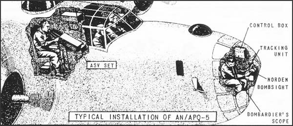
| DESCRIPTION: | Bombing attachment to microwave ASV sets and Norden bombsight. Set is equipped with an expanded B scope, with range sweeps of 1 and 10 miles. |
|---|---|
| USES: | designed for low altitude (65-4000 ft.) blind bombing of marine targets. Does not interfere with use of Norden bombsight in visual bombing. |
| PERFORMANCE: | Automatically releases bombs on isolated radar target selected and tracked by bombardier on AN/APQ-5 indicator. Average bombing error from center of target from 1000 ft. altitude: range ± 75 ft., deflection ± 125 ft. A bombing run up to 10 miles may be used. |
| TRANSPORTABILITY: | Packed in 4 boxes, weighing a total of 200 lbs. |
| INSTALLATION: | Permanently installed near gyro stabilizer and electrically connected to ASV equipment in heavy bombers equipped with microwave ASV. Installed weight is 125 lbs. |
| PERSONNEL: | Bombardier must have additional training on operation of AN/APQ-5. Radar operator and mechanic normally assigned can perform other functions. |
| POWER: | Requires 350 watts at 110 v 400-800 cycles AC from power supply for basic ASV equipment, plus about 25 watts of 28 v DC. |
--76--
*AN/APS-15 Microwave ASV and High Altitude Bombing Set
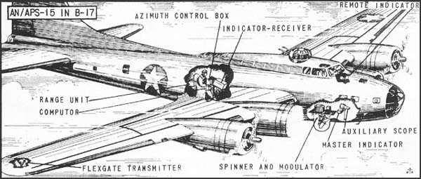
| DESCRIPTION: | Airborne microwave search set for installation in large and medium patrol bomber aircraft. Provides both ground and slant range, relative and true bearing of target, and true bearing of aircraft on "PPI" scopes, furnished to operator and pilot. Sometimes described as H2X. |
|---|---|
| USES: | For locating and homing on friendly or enemy surface craft and on coastlines; for general navigation; and for bombing of marine, coastal, and land targets of pronounced definition. Set has provisions for operating on racon (AN/CPN-6) and IFF connections for identification of targets. |
| PERFORMANCE: | Reliable maximum ranges: harbor buoys, 15 nautical miles; 5,000 ton ship, 40 nautical miles; large coastal city, 95 nautical miles. Minimum range is 200 yards. Range accuracy, ± 1%. Covers 360° of bearing with accuracy in bombing of ± 1/4 mile. Antenna is designed to give coverage at all elevation angles between 0° and 80° without changing tilt. |
| TRANSPORTABILITY: | Packed in 7 units for shipment, and weighing a total of 760 lbs. Largest unit measures 591/2" x 47" x 29" and weighs 370 lbs. |
| INSTALLATION: | Installed weight in B-24 is 370 lbs. Effect on plane's speed is negligible. |
| PERSONNEL: | One operator and one maintenance man per set are required by Army. Navy requires one operator per set and 4 maintenance men per squadron. |
| POWER: | Total primary power required: (a) from combination AC-DC primary generator -- 10 amps. 27.5 volts DC and 1050 watts 115 V 400-2400 cycles AC; or (b) from DC primary generator, requiring use of motor alternator -- 70 amps. 27.5 V DC. |
* Available for issue in latter part of 1943.
--77--
[B L A N K]
--78--
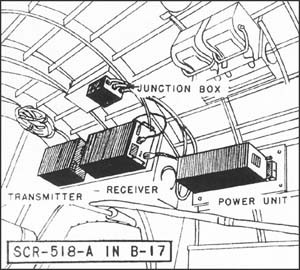
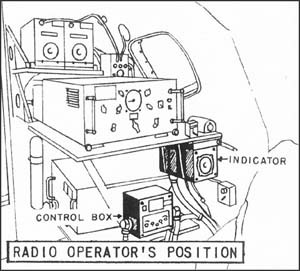
| DESCRIPTION: | Absolute pulse radar altimeters. |
|---|---|
| USES: | For measuring absolute altitude in high-altitude bombing, photographic mapping, terrain clearance. |
| PERFORMANCE: | SCR-518-A and AYA operate between 50 ft. and 20,000 ft. Accuracy is ± (50 ft. plus 1/4%). |
| TRANSPORTABILITY: | SCR-518-A is packed for shipment in one unit, weighing about 150 lbs. and occupying 30 cu. ft. AYA is packed in 3 units, weighing 207 lbs. Largest unit measures 30" x 281/2" x 261/2". |
| INSTALLATION: | Average installed weight of SCR-518-A and AYA is 100 lbs., effecting a drag of not over 10 lbs. at 250 mph. Indicator (a cathode ray tube) cannot be successfully mounted where pilot can use it. |
| PERSONNEL: | Altimeter is operated by the radar operator or bombardier, and can be serviced by regular radar maintenance personnel. |
| POWER: | Total primary power required is 11 amps., 27.7 v. DC for SCR-518-A and AYA. |
--80--
*SCR-718 Pulse Altimeter
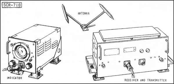
| DESCRIPTION: | Absolute pulse radar altimeter. |
|---|---|
| USES: | For measuring absolute altitude in high-altitude bombing, photographic mapping, terrain clearance. |
| PERFORMANCE: | SCR-718 operates between 50 ft. and 40,000 ft. Accuracy is ± 50 ft. plus 1/4%. |
| TRANSPORTABILITY: | SCR-718 is crated in one unit weighing about 60 lbs., and occupying about 12 cu. ft. |
| INSTALLATION: | SCR-718 weighs 40 lbs. installed and is mechanically and electrically interchangeable with AN/APN-1 except for indicator and AC power connection. |
| PERSONNEL: | Altimeter is operated by pilot and can be serviced by regular radar maintenance personnel. |
| POWER: | 135 watts, 115 volts, 400-2600 cycles AC. |
* Available for issue in latter part of 1943.
--81--
AYB, AN/ARN-1 (RC-24 & AYD-5) & AN/APN-1 (AYF)
Low Altitude FM Altimeters
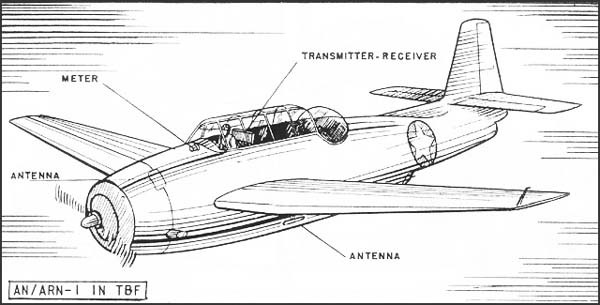
| DESCRIPTION: | Absolute FM radar altimeters. |
|---|---|
| USES: | for use in sea search, torpedo launching, low-altitude bombings, as a photographic aid, or landing aid. Indication is provided on a meter. |
| PERFORMANCE: | All sets operate between 5 and 400 feet, measuring altitude with an accuracy of ± (5' + 5%). AN/APN-1 also operates between 400 ft. and 4,000 ft., with an accuracy of ± (60 ft. + 5%). |
| TRANSPORTABILITY: | Sets including spares for 200 hrs., packed for shipment in two units weighing about 60 lbs. Largest package measures 25" x 171/2" x 151/2". |
| INSTALLATION: | Average installed weight is 35 lbs., producing a drag of not over 15 lbs. at 300 mph. |
| PERSONNEL: | Altimeter is used by the pilot. Regular radar maintenance personnel can service the equipment. |
| POWER: | Sets require primary power of about 75 watts 28 v. DC, from plane's DC supply. |
--82--
SCR-640, SCR-621 or YH, & *YJ Long Wave Racons
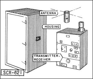
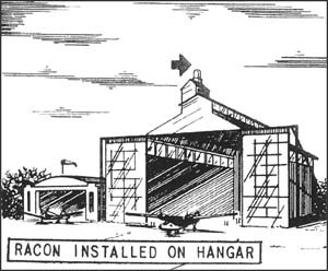
| DESCRIPTION: | Long wave racons, transmitting a coded identification signal when triggered by radar in planes. YJ is fixed; SCR-640, SCR-621 and YH are fixed or mobile. |
|---|---|
| USES: | For homing friendly aircraft to their bases, or as a general navigational aid. SCR-640 works with SCR-540 airborne set; YJ and SCR-621 or YH with SCR-521, ASVC and ASE airborne sets. YJ also works with ASB sets. |
| PERFORMANCE: | YJ has a reliable maximum range of 80 mi. Other sets have a reliable range of 85 mi. Range accuracy is ± 5%. Azimuth limits: 360°. |
| TRANSPORTABILITY: | YJ will be crated in 3 units for shipment. Total weight is 550 lbs. Largest unit is 72" x 24" x 24" and weighs 225 lbs. All other sets, without generator, are packed for shipment in 3 units, weighing a total of 660 lbs. The largest unit is 24" x 24" x 48" and weighs 300 lbs. (Antenna tripod measures 12" x 12" x 144"). With generator, sets are packaged in 5 units, weighing a total of 1000 lbs. Largest package is 44" x 33" x 26", and weighs 475 lbs. Shipments include spare tubes for 1,000 hrs. |
| INSTALLATION: | Sets should be sited at any ground location accessible by motor vehicle (YH and YJ are also installed on ships.) The 20' antenna should be clear of surrounding objects for a radius of 100 yds. 3 maintenance men can install racon in 3 hours; if truck-mounted, racon can be put in operation by 1 man in 1 hour. |
| PERSONNEL: | No operators are required, but maintenance men should make a 10-minute check every 4 to 8 hours. Consideration is being given to continuous monitoring in view of importance of navigational facilities provided. |
| POWER: | Total primary power required is 150 watts (for YJ) and 419 watts (for other sets), 115-230 v., 50-70 cycles, AC. Gas engine driven generator, supplied on request, uses standard 70-80 octane gas at rate of 0.25 gal. per hour. |
* Available for issue in latter part of 1943.
--83--
*AN/CPN-3 (SCR-620 or YK) and AN/CPN-6 Microwave Racon
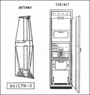
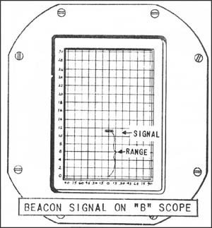
| DESCRIPTION: | Microwave fixed ground or shipborne racon, transmitting coded identification signals when triggered by radar in plane. |
|---|---|
| USES: | For homing friendly planes to their bases, and as a general navigation aid. AN/CPN-3 works with SCR-520, SCR-720, SCR-517, SCR-717, ASC and ASB airborne sets. AN/CPN is a microwave racon with essentially the same characteristics as AN/CPN-3, except that AN/CPN-6 works with SCR-717-T3, ASD, AIA, AN/APS-4 (ASH), AN/APS-3 (ASD-1) and AN/APS-15. |
| PERFORMANCE: | AN/CPN-3's reliable maximum range is 100 mi. Range accuracy, ± 5%. Azimuth limits: 360°. |
| TRANSPORTABILITY: | Without generator, AN/CPN-3 is crated in 5 units weighing 1,000 lbs. Largest is 24" x 24" x 48" and weighs 400 lbs. With generator, set is packed in 6 units, weighing 1500 lbs. Largest package is 44" x 33" x 26" and weighs 475 lbs. |
| INSTALLATION: | Antenna should be mounted as high as practicable above surrounding terrain, or on highest part of ship. Since antenna location is critical, a competent engineer should select site. Three trained men can install and adjust equipment in a day on a ship, or 3 hours on shore. |
| PERSONNEL: | No operator is required, but maintenance man should make 10-minute check every 4 to 8 hours. Consideration is being given to continuous monitoring in view of importance of navigational facilities provided. |
| POWER: | AN/CPN-3 requires about 1000 watts AC, supplied by any 50-70 cycle 115-230 v. AC source, or by gas engine driven generator furnished on request. Generator uses standard 70-80 octane gas at rate of 0.65 gals. per hour. |
* Available for issue in latter part of 1943.
--84--
*AN/TPN-1 and *AN/PPN-1 Light Weight Long Wave "Eureka" Racons
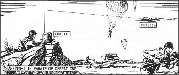
| DESCRIPTION: | AN/TPN-1 is a light-weight transportable airdrome homing racon; AN/PPN-1 is a very light-weight paratroop pack-set racon. Five transmitting frequencies and 5 receiving frequencies are available. Sets transmit when interrogated by AN/APN-2. |
|---|---|
| USES: | For homing AN/APN-2 equipped aircraft to an airdrome, or to a predetermined spot for paratroop dropping, ground support, etc. |
| PERFORMANCE: | When used with AN/APN-2, AN/APN-1 has a reliable maximum range of 50 miles at 2500 feet; AN/PPN-1, of 30 miles at 1500 feet. |
| TRANSPORTABILITY: | AN/TPN-1 weighs about 150 lbs., complete, and is air transportable. AN/PPN-1 weighs about 30 lbs., complete, and can be carried in pack of paratroopers. |
| INSTALLATION: | Ground location chosen by tactical requirements. AN/TPN-1 can be transported by motor vehicle, and set up by one man in from 15 minutes to an hour, depending on accessibility of antenna location. The 9-ft. antenna should be erected on as high a point as practical, in order to clear surrounding terrain. AN/PPN-1 is set up by paratrooper on as high as site as possible at location where other troops are to be dropped. Set-up time is about 10 minutes. |
| PERSONNEL: | AN/PPN-1 is operated by one man. AN/TPN-1 requires no operator, but should be checked by maintenance personnel every 8 hours. (Six maintenance men are assigned to a Troop Carrier squadron for servicing all radar equipment.) |
| POWER: | Power requirements of some AN/TPN-1 sets are supplied by 24-v. storage battery; others use 110-v. power source. AN/PPN-1 requires 15-20 watts from self-contained batteries, sufficient for 6 to 8 hours' operation. |
* Available for issue in latter part of 1943.
--85--
*AN/APN-2 Airborne Long Wave "Rebecca" Interrogator-Responsor
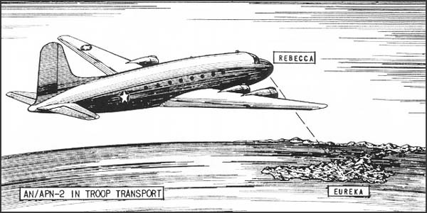
| DESCRIPTION: | Airborne interrogator-responsor, with modified "A" indication, showing range and relative azimuth of the transpondor. Five transmitting frequencies and 2 receiving frequencies are available. |
|---|---|
| USES: | For interrogating and homing on AN/TNP-1 and AN/PPN-1 transpondors. |
| PERFORMANCE: | Line-of-sight range up to a maximum of 50 miles on AN/TPN-1 transpondor. Reliable maximum range of 30 miles on AN/PPN-1. Both sets have range accuracy of ± 5%, azimuth accuracy of ± 5°. |
| TRANSPORTABILITY: | Set is shipped in 5 boxes, with a total crated weight of approximately 100 lbs. and a total crated volume of 10.22 cu. ft. Largest unit is the receiver-transmitter, 121/2" x 81/2" x 121/4", with a weight of 34 lbs., and a crated weight of 42 lbs. |
| INSTALLATION: | Installed in troop carrier planes. Installed weight is 85 lbs. |
| PERSONNEL: | AN/APN-2 is operated by plane's radio operator or navigator, and serviced by one of 6 radar maintenance men assigned to Troop Carrier Squadron. |
| POWER: | 180 watts, 115 v., 400 cycles, AC, and 10 watts, 24 v., DC. from plane's DC supply and generators. |
* Available for issue in latter part of 1943.
--86--
LORAN Long-Range Navigation System
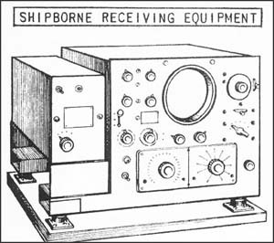
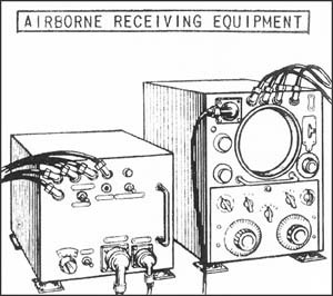
| DESCRIPTION: | Long wave, long-range precise navigational system, comprising shore-based transmitters, and shipborne or airborne receivers. |
|---|---|
| USES: | For navigation of ships and planes. |
| PERFORMANCE: | Maximum range for ships is about 700 nautical miles by day and 1400 nautical miles by night; for planes, about the same as for ships over sea water but only 250 miles over land by day and 1200 miles over land by night. Accuracy varies, but the maximum total error of fix will seldom be as large as 1% of the mean distance from the transmitting stations. Maximum accuracy is about 1 or 2 miles. |
| TRANSPORTABILITY: | Transmitting equipment is large and bulky, several carloads being necessary. Shipborne receivers are crated in 1 or 2 boxes; largest is 31" x 25" x 22" and weighs about 225 lbs. Airborne receivers (AN/APN-4 or SCR-622) are in 4 boxes; largest of 24" x 14" x 10", and total shipping weight is about 90 lbs. |
| INSTALLATION: | Transmitting stations must be units in a chain of stations. selection of areas to be served by the Loran system is made under the cognizance of the Joint Chiefs of Staff; installation, maintenance, and operation of the stations at present are the responsibility of the Navy and Coast Guard. Shipborne receiving equipment weighs 120 lbs. installed; airborne receiving equipment, about 71 lbs. with cables. |
| PERSONNEL: | Transmitting stations require a normal operating crew of from 10 to 15 operators and maintenance men for 24-hour service. Receivers are operated by the plane's or ship's navigator. |
| POWER: | Single-pulsed transmitting station requires 5 KW, 110/220 v., 60 cycles, AC, from motor generator furnished with set. Double-pulsed stations, complete with standby equipment, require 10 to 15 KW. Shipborne receiver requires 240 watts from 110 v. 60 cycles, AC; airborne receiver, 240 watts from 110 v. 400 cycles, AC. |
--87--
[B L A N K]
--88--
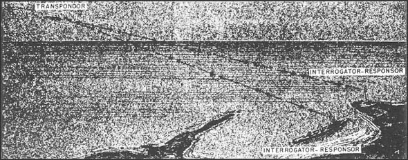
IFF is an abbreviation of the phrase "identification of friend or foe." Since radar is used to direct gun fire or bombing at night, or in daylight when the target is beyond the range of visibility, it is obviously important that there be radar equipment that will serve to identify instantly any aircraft or ship as friend or foe before attack.
There are two basic components in any identification system at present in use: (1) the transpondor, carried by the aircraft or ship to be identified; (2) the interrogator-responsor, or questioning device, located aboard a ship, at a ground station, or in another aircraft.
The transpondor on a plane (or ship) is a combination radio transmitter and receiver, packaged in one small box. Normally, the transpondor is in a receiving condition, and will continue to function as a receiver until it receives a radio signal. Then, the transpondor will automatically become a transmitter and, as such, will transmit a signal in reply to that received. (The transpondor is said to have been triggered.)
In the identification systems now in use the transpondor when functioning as a receiver mechanically sweeps a band (or bands) of frequencies within a few seconds. If during a sweep through the
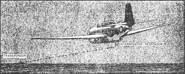
--90--
frequency band a radio signal within that band is received, the transpondor will send back the received signal within a fraction of a second, and will transmit the signal on the same frequency on which the signal was received. In effect, then, the transpondor acts as a selective mirror to radio signals.
The interrogator-responsor is also a transmitter and receiver. The transmitter (interrogator) is designed to permit triggering a transpondor. The receiver (responsor) gets the automatic transmitted reply from the transpondor, and by means of additional equipment displays this transmitted reply on a radar scope.
Two IFF systems are in use at present by American and British forces. They are:
| (1) | IFF Mark II, and |
| (2) | IFF Mark III. |
Both systems use the same basic components--an airborne (or shipborne) transpondor, and an interrogator-responsor (which in the Mark II system is the search radar)--and operate on the same principle. The basic difference between the Mark II and Mark III systems is that the Mark III is a universal system.
The Mark II transpondors alternately sweep two or three bands of frequencies, but their bands are not common to all transpondors. Mark III transpondors sweep only one band of frequencies. The reason for this difference between the transpondors becomes obvious when their interrogators are examined.
Mark II System
In general, the Mark II system's interrogator-responsor unit is the ground, shipborne, or airborne search radar set. In the Mark II system there is no separate interrogator-responsor (IR) unit -- the regular radar search equipment, without any extra gadgets, serving as an interrogator-responsor.
Use of the Mark II system has required the airborne transpondors to be capable of replying to all types of radar interrogation employed throughout the various operational areas.
The multiplicity of radar frequencies now being used presents definite limitations to the successful operation of the Mark II system. However, its use continues as an interim measure until all British and American forces are equipped with the several components necessary to operation of the Mark III system.
Mark II Scope Display
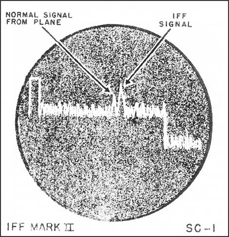
Since the radar set alone performs the interrogator-responsor function in the Mark II system, the transpondor is triggered (i.e., automatically transmits) each time the transpondor sweeps through the frequency of the interrogating radar. When the transpondor has been triggered, the operator of the interrogating radar will observe on his scope a signal similar to a strong echo at the same or a slightly greater range than the echo made by the reflecting object itself.
The transpondor sweeps through the frequency of the interrogating radar once every six seconds. Because of the regular recurrence rate of the transpondor's signal (echo), this signal is recognized by the radar operator as an IFF reply.
A typical IFF Mark II scope presentation on an AC-1 radar set is pictured above.
--91--
Mark III System
In the Mark III system, identification is accomplished on a single band. This universal Mark III band is designated as "A" band by the Navy, and "I" band by the Army.
The Mark III system requires special interrogator-responsor equipment to be installed to supplement practically all radar sets. Installation of this IR equipment is arranged so that the IFF reply from a transpondor is shown on the interrogating radar's scope.
Scope presentations vary in the Mark III system. But no IFF signal appears on the radar scope until the interrogator key (challenge switch) has been pressed by the radar operator, unless it so happens that the radar frequency lies within the Navy's A (Army's I) band. Below is a picture of an IFF Mark III presentation on the A scope of an SM radar or an SCR-270 radar.
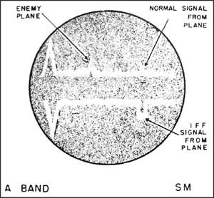
After the interrogator key has been pressed by the operator, he then observes that the radar pips denoting friendly planes have corresponding identification pips appearing downward. Therefore, all radar pips not having an identification pip below denote unidentified planes. (On some radar sets the display splits into two, as shown in the picture above). Further substantiating evidence must generally be presented before the term "enemy" can be appended to unidentified planes.
The Mark III reply may be coded to provide additional security and identify special missions.
Mark III G Band
Besides the universal Mark III band, the Mark III system also has a G band reply for fighter planes only. The Navy A band (Army I) transpondor serves to identify all aircraft (including fighters) as friend or foe on the interrogating radar's scope; the G band transpondor further identifies friendly fighter aircraft on the interrogating CGI (SCI) radar's PPI scope.
Reason for the extra G band is that in GCI or SCI work it is often vital to segregate friendly fighters from other friendly or enemy craft so as to organize an interception. The PPI, of course, is the scope used in directing GCI work. How a G band reply appears is shown below.
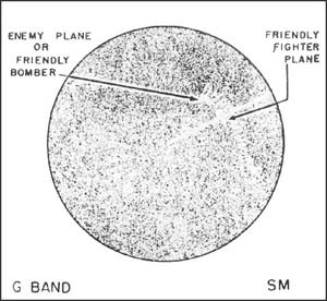
The IFF Mark III G band display is shown only in response to a vocal request from the GCI station. The fighter plane pilot then turns a switch that causes a pattern similar to the one above to appear on the PPI. The IFF signal is symmetrical about the azimuth of the friendly plane. The friendly bomber or enemy plane shown on the above scope at the same range as the friendly fighter is thus distinguished the identity of other planes must be determined on the radar's A scope.
--92--
Interrogators and responsors are invariably used together. In some cases, too, interrogator, responsor and transpondor are all combined in a single unit; this system being known as IRT.
In addition to serving for identification purposes, IFF equipment has other special applications.
One of these is for racon interrogation by planes not equipped with search radars or equipped with search radars of a frequency not suitable for beacon interrogation. The frequency band covered by the IFF Mark III system makes it possible for airborne IR's (SCR-729 and AN/APX-2) to interrogate radar beacons covering the same frequency band, as is indicated in the description of these IR equipments in this book.
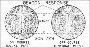
The SCR-729 can home on these radar beacons because it is installed with antennas suitable for lobe switching and the resulting pip matching needed in homing, as well as with an indicator needed for displaying the homing signals (see picture above).
AN/APX-2 can be adjusted for homing on beacon signals by employing a similar antenna system plus a lobe switching motor and a display device. The display device and switching motor used for this purpose is the AN/APA-1.
When a radar beacon is carried in a plane so that other aircraft can home on the plane, the beacon is called a rooster.1 A typical rooster operation is shown below -- the scout plane pilot calling other planes from the carrier while continuing to shadow the enemy convoy.

Any airborne transpondor can be used as a rooster (1) if it has a fixed or spot frequency band, such as AN/APX-1 or the more versatile AN/APN-8, or (2) if the arm in the equipment that causes the sweep is removed. Since homing is done by pip matching, as is illustrated above [top image], rooster operations are difficult with the ordinary IFF transpondors that sweep a relatively wide frequency band at a slow rate.
The AN/APX-2 plus the AN/APA-1 when installed in a plane will serve the following functions: (1) transpondor; (2) IR; (3) rooster response so other planes can home; (4) rooster interrogation to home on another plane; (5) or (depending upon interrogating frequency) interrogation and response from YH (SCR-621) or YJ racons. Similarly the SCR-729 plus the SCR-695 (weighing about 1/3 more) will serve the same functions except for (3) above.
A final application of IFF is in aiding a plane in distress. A switch (marked "emergency") is provided so that when turned by the pilot the IFF replies with a distinctive and extra wide pulse -- thus allowing friendly planes to recognize and home on the disabled plane.
1. For other types of beacons see RACON in glossary at end of book.
--93--
NOTE:
In possible future editions of this publication, it is hoped that full information on the designations of british as well as U.S. IFF equipment will be given, and British units which will work with corresponding U.S. units will be catalogued in full. In what follows, correct but incomplete information of this sort has been attempted. Equipment of the Royal Navy and of the Royal Air Force is listed, not always completely, and all equipment of the British Army is omitted.
--94--
SCR-535 or ABE, & ABD Mark II Airborne Transpondors
| DESCRIPTION: | IFF Mark II airborne transpondors which alternately sweep two frequency bands providing uncoded radar response to challenges within their two frequency bands. These transpondors are basically the same, differing only in frequency range of one band. |
|---|---|
| USES: | For identifying friendly plane to ground or ship radar stations ABD responds to following search radars: Royal Navy 286, 286M, 286P, 290, 291, 241. ABD responds to following Airborne Interrogator-Responsors: Navy AN/APX-2 ABE responds to following search radars: Royal Navy 79, 279, 286, 286P, 290, 291, 241, 286M. ABE responds to following Airborne Interrogator-Responsors: Navy AN/APX-2. |
| PERFORMANCE: | Maximum range is 75 miles; minimum, 1 mile. |
| TRANSPORTABILITY: | Sets (including spares) are packaged for shipment in 4 units, weighing a total of about 100 lbs. Largest unit is 15" x 15" x 30" and weighs about 45 lbs. One set of test equipment is supplied with every 10 sets. |
| INSTALLATION: | Installed weight is 45 lbs. |
| PERSONNEL: | In operation sets normally require only turning on and off by pilot. (see SD158). One maintenance man per squadron is needed. |
| POWER: | Primary power required is 12 v., 5 amps. or 24 v., 2.5 amps., DC, depending on model used. Source is plane's battery and generator system. |
--95--
SCR-595, ABK or BK Mark III Airborne or Shipborne Transpondors
| DESCRIPTION: | IFF Mark III Airborne transpondor which sweeps a single band of frequencies (designated by the Navy as the A band and by the Army as the I band) and provides a coded reply for reception by a responsor throughout the band. Adapted to ship use with motor generator and type 66-ACG antennas. |
|---|---|
| USES: | For identifying friendly planes or ships to properly equipped aircraft, ship, or ground stations. ABJ responds to:
Army (Ground Interrogator-Responsors RC-107, RC-127, RC-136, RC-145, RC-148, RC-150, RC-151, RC-157, RC-182, RC-184, RC-188, RC-192, RC-215, RC-282. Royal Navy Interrogator-Responsors 242, 243. Navy (Airborne) Interrogator-Responsors AN/APX-2; Radars ASE, ASVC. Army (Airborne) Interrogator-Responsors SCR-729; Radars SCR-521-A, SCR-521-B. |
| PERFORMANCE: | Maximum reliable range is 90 miles, (125 miles using RC-150 or RC-151). Minimum range is 1 to 10 miles, depending on the associated interrogator. |
| TRANSPORTABILITY: | Set is packed for shipment in 4 units, weighing approximately 100 lbs. Largest package is about 15" x 15" x 30" and weighs about 45 lbs. Navy supplies one test equipment with every 10 sets. Army supplies 4 test equipments to a fighter squadron, 3 to a light dive bomb squadron, and 2 for all other squadrons. |
| INSTALLATION: | Installed weight is 60 lbs. plus a 214-lb. motor generator when installed on ship. |
| PERSONNEL: | In operation, set normally requires only turning on and off by pilot or operator (see SD158). Navy sets are serviced by regular radar maintenance personnel. Army recommends 4 maintenance men per fighter squadron, 3 per light/dive bomb squadron, and 2 for all other squadrons. |
| POWER: | Required primary power is 12 v., 10 amps., or 24 v., 5 amps., DC, depending on model used. Source is plane's battery and generator system or motor generator on ships. |
--96--
SCR-692 or ABF Mark III Airborne Transpondor
| DESCRIPTION: | IFF Mark III airborne transpondor similar to the ABK in that it sweeps the Navy A band frequencies (Army's I band) providing a coded reply for reception by a responsor upon being challenged on a frequency in the band. In addition to this function, the SCR-695 is provided with a second transpondor which operates on a fixed frequency that may be adjusted over a range designated as the G band. This G band transpondor provides a frequency channel for interceptors operating with ground and shipboard GCI units. |
|---|---|
| USES: | The A Band transpondor serves to identify the aircraft as friendly and its G band transpondor further identifies the aircraft as a fighter directly on the GCI PPI indicator. SCR-695 (ABF) responds to:
Army (Ground) Interrogator-Responsors RC-107, RC-127, RC- 36, RC-145, RC-148, RC-150, RC-151, RC-157, RC-182, RC-184, RC-188, RC-192, RC-215, RC-282; Radars SCR-527, SCR-545, SCR-588, SCR-602, SCR-627. Royal Navy Interrogator-Responsors 242, 243. Navy (Airborne) Interrogator-Responsors AN/APX-2; Radars ASE, ASVC. Army (Airborne) Interrogator-Responsors SCR-729; radars SCR-521-A, SCR-521-B. |
| PERFORMANCE: | Reliable maximum range is 90 miles (125 miles with RC-150 or RC-151). Reliable minimum range is 1 to 10 miles, depending on associated interrogator. |
| TRANSPORTABILITY: | Set is packed for shipment in 1 unit weighing a total of 45 lbs., plus Group A parts shipped in bulk. Largest unit is about 15" x 15" x 30" and weighs about 50 lbs. Navy supplies one test equipment with every 10 ABF sets; Army supplies 4 test equipments to a fighter squadron, 3 to a light/dive bomber squadron and 2 to all other squadrons. |
| INSTALLATION: | Installed weight is 60 lbs. |
| PERSONNEL: | Set normally requires only turning on and off and occasionally switching operation by pilots (see SD158). Navy sets are serviced by regular radar maintenance personnel. Army recommends 4 maintenance men per fighter squadron, 3 per light/dive bomb squadron and 2 for all other squadrons. |
| POWER: | Primary power required is 10 amps., 12 v. DC (for model SCR-695-AZ) and 5 amps., 24 v. DC (for model SCR-695-A and ABF), from plane's battery and generator system. |
--97--
*AN/APX-1 Mark III Airborne Transpondor
| DESCRIPTION: | IFF Mark III airborne transpondor similar to the SCR-695. Its G band frequency determining unit is replaceable which permits a larger band of frequencies to select from. It is provided with facilities for operation as an airborne radar beacon (rooster) on any fixed frequency within the G band. |
|---|---|
| USES: | For use in fighter aircraft to enable ground and shipboard fighter director units to identify aircraft so equipped as friendly fighters. For use in patrol and scout aircraft to furnish a beacon response to friendly radar equipped aircraft. AN/APX-1 responds to:
Army (Ground) Interrogator-Responsors RC-107, RC-127, RC-136, RC-145, RC-148, RC-150, RC-151, RC-157, RC-182, RC-184, RC-188, RC-192, RC-215, RC-282; Radars SCR-527, SCR-545, SCR-588, SRC-602, SCR-627. Royal Navy Interrogator-Responsors 242, 243. Navy (Airborne) Interrogator-Responsors AN/APX-2; Radars ASE, ASVC. Army (Airborne) Interrogators-Responsors SCR-729; Radars SCR-521-A, SCR-521-B. In addition works as an airborne radar beacon (rooster) and will respond as such to ASE, ASVC, SCR-521-A and SCR-521-B. |
| PERFORMANCE: | Reliable maximum range is 90 miles; minimum range, 1 mile. |
| TRANSPORTABILITY: | Set is packed for shipment in 4 units, weighing approximately 100 lbs. Largest unit is about 15" x 15" x 30" and weighs about 45 lbs. Spares and test equipment are included. |
| INSTALLATION: | Installed weight is about 50 lbs. |
| PERSONNEL: | Set normally requires only turning on and off, plus occasional switching operations. This is done by the pilot in single-seated fighters, or by the radar operator in multi-placed planes (See SD-158). One maintenance man per squadron is required. |
| POWER: | Required primary power of 5 amps. 24 V or 11 amps. 12 V DC is from plane's battery and generator system. |
* Available for issue in latter part of 1943.
--98--
*AN/APX-2 (ABJ) Mark III Airborne IRT
| DESCRIPTION: | IFF Mark III airborne combination Interrogator-responsor-transpondor. As a transpondor and radar beacon (rooster), this equipment is identical to the AN/APX-1. In addition, it is provided with interrogator-responsor facilities on any fixed frequency within the Navy A band frequency limits. |
|---|---|
| USES: | For use in all search radar equipped aircraft. Its IFF transpondors permit aircraft so equipped to be identified as friendly by a ground, ship or aircraft fitted with an A band interrogator-responsor. As a radar beacon, it permits other radar equipped aircraft to home to it (assuming correct frequency adjustments). As an interrogator-responsor, it permits aircraft so equipped to identify as friendly all ships and aircraft fitted with any IFF Mark III A band transpondor. When utilized with a suitable antenna system, the AN/APX-2 may be used to interrogate and home to ground radar beacons operating within the limits of the A band frequencies. Operation of the AN/APX-2 is also possible in aircraft not fitted for radar. This may be accomplished by the utilization of the indicator (display) unit of the SCR-729 or the ASE remote indicator AN/APA-1. AN/APX-2 respond to: Navy (Ship) Interrogator-Responsors BL, BN, BM, BO; Radars SC, SA. Army (Ground) Interrogator-Responsors RC-1097, RC-127, RC-136, RC-145, RC-148, RC-150, RC-151, RC-157, RC-182, RC-184, RC-188, RC-192, RC-215, RC-282; Radars SCR-527, SCR-545, SCR-588, ASCR-602, SCR-627. Royal Navy Interrogator-Responsors 242, 243. Navy (Airborne) Interrogator-responsors AN/APX-2; Radars ASE, ASVC. Army (Airborne) Interrogator-responsors SCR-729; Radars SCR-521-A, SCR-521-B. In addition, as an Interrogator-responsor it will interrogate for reply any ship or airborne Mk III IFF "A" band transpondor, such as BK, ABK, SCR-595, SCR-695, AN/APX-1, AN/APX-2, RAF-3090, 3120, 3121, and rn-253. As an airborne beacon (rooster) responds to ASE, ASVC, SCR-521-A and SCR-521-B. |
| PERFORMANCE: | Reliable maximum range for transpondors is 90 miles; for interrogators and responsors, 60 miles. Minimum range is 2 miles. |
| TRANSPORTABILITY: | Set will be packed for shipment, with spares and testing equipment in 4 units. Total weight will not exceed 100 lbs. |
| INSTALLATION: | Installed weight of set is 52 lbs. |
| PERSONNEL: | Set will be operated by the pilot in single-seated aircraft, or by the radar operator in multi-place planes. One maintenance man per squadron is recommended. |
| POWER: | Required primary power is 115V, 400-2400 cycles at 150 watts, plus 25 watts DC at 24 V. |
* Available for issue in latter part of 1943.
--99--
*AN/APA-1 Pilot Repeat Indicator
| DESCRIPTION: | Pilot repeat indicator for any ASB or ASE radar, or for IFF Mark III interrogator-responsor-transpondor AN/APX-2, or for some forms of SCR-729. |
|---|---|
| USES: | When used with search radar, provides navigational and tactical data to pilot. Used as a blind bombing aid in conjunction with ASB. For IFF application, AN/APA-1 provides separate display for identification of other aircraft, racon and rooster homing facilities. |
| PERFORMANCE: | Corresponds to that of associated search radar or IFF IR unit. |
| TRANSPORTABILITY: | Shipment, including operating spares, is packed in one or two units. |
| INSTALLATION: | Installed weight is 35 lbs. |
| PERSONNEL: | Indicator is used by pilot, or by radar operator in some applications, and serviced by regular radar maintenance personnel. |
| POWER: | Required primary power is 85 watts, 115 V, 400-2400 cycles AC, plus about 20 watts, 20-30 V, DC. |
SCR-729 Mark III Airborne IR
| DESCRIPTION: | IFF Mark III airborne interrogator-responsor. |
|---|---|
| USES: | When operated with a suitable antenna system, its installation permits aircraft so equipped to challenge and identify as friendly aircraft and ships equipped with any Navy A or Army I band transpondor. In addition, it may be used to interrogate and home on YH, YJ and SCR-621 radar beacons, and on BABS beach approach beacon of the R.A.F. Works with ABK, AN/APX-1, AN/APX-2, SCR-695 and SCR-595, RAF 3067, 3090, 3120, and 3121; Royal Navy 253. Display of identification or homing facilities may be obtained on SCR-729 "A" scope or the scope of the associated radar equipment. |
| PERFORMANCE: | Reliable maximum range is 60 miles, minimum range is 20 miles. Azimuth limits are 80° forward, with accuracy (when homing on beacon) of ± 2°. Elevation limits are 40° forward. |
| TRANSPORTABILITY: | Set is packed for shipment in 5 units, weighing a total of about 190 lbs. Spares and testing equipment are included. |
| INSTALLATION: | Installed weight is 150 to 115 lbs., depending on type of antenna used. |
| PERSONNEL: | Set requires on operator, who may be the regular radar operator or a specially trained radio operator. One maintenance man per squadron is needed. |
| POWER: | Required primary power is 150 watts, 115 v., 400-2400 cycles, plus 25 watts DC at 24 v. (for SCR-729-A) or 25 watts DC at 12 v. (for SCR-729-AZ.) |
* Available for issue in latter part of 1943.
--100--
*AN/APN-8 Airborne Radar Transpondor Beacon
| DESCRIPTION: | Airborne radar transpondor beacon. The main units has the same form factor as the ABK and is interchangeable in the ABK shock mount. |
|---|---|
| USES: | Set is an airborne version of the YJ ground radar and consists of two transpondors that receive and respond on different frequencies. Permits planes equipped with SCR-517, SCR-521, ASV, ASVC, ASE and ASB to home on it. Also, planes fitted with centimeter-type radars (or no radars at all) may home on it if the planes are provided with AN/APX-2 with suitable antennas and accessories (AN/APA-1) or SCR-729. |
| PERFORMANCE: | Reliable maximum range: 60 miles; reliable minimum, 2 miles. Range accuracy is 0.2 miles. Azimuth and elevation accuracy is determined by interrogator. |
| TRANSPORTABILITY: | Shipment includes spares for 1000 hours operation, testing equipment and separate generator if needed. Complete shipment is packed in 3 units and weighs about 90 lbs. Largest package is 15" x 15" x 20" and weighs 40 to 50 lbs. |
| INSTALLATION: | Installed weight is approximately 60 lbs. |
| PERSONNEL: | Radio or radar operator. |
| POWER: | Requires primary power of 200 watts DC at 12 or 24 volts. Source is plane's battery. A dynamotor is supplied. |
BL and *BM Mark III (A Band) Shipborne IR
| DESCRIPTION: | IFF Mark III (A band) shipborne interrogator-responsor. BM is improved version of BL. |
|---|---|
| USES: | Interrogates Mark III transpondors (ABK, SCR-595, SCR-695, ABF, AN/APX-1, AN/APX-2) and gives an IFF reply on the radar scope. |
| PERFORMANCE: | Reliable maximum ranges: for BL, 90 miles; for BM, 100 miles is expected. |
| TRANSPORTABILITY: | Shipments of both sets include spares. BM has testing equipment as integral part. BL is packed for shipment in 2 units and weighs when crated a total of 375 lbs. BM is packed in 3 packages. Both sets are air transportable. |
| INSTALLATION: | BL has 4 components weighing a total of approximately 274 lbs. The equipment component is 20" x 30" x 203/4" and weighs 250 lbs. BM has 2 components, weighing a total of 585 lbs. The equipment component is 30" x 20" x 203/4" and weighs 275 lbs. |
| PERSONNEL: | Usually no additional personnel required -- the associated radar personnel serving. |
| POWER: | Primary power required is 300 watts for BM, and 400 watts for BL, 110 v AC, 60 cycles. Source is ship's power or supply of associated radar. |
* Available for issue in latter part of 1943.
--101--
BN Mark III (A Band) Low Power Shipborne IR
| DESCRIPTION: | IFF Mark III (A band) low-power shipborne interrogator-responsor. |
|---|---|
| USES: | RN is designed primarily for small ships and boats for use with surface search and fire control shipborne radars. It interrogates Mark III transpondors (chiefly ABK) and gives IFF reply to the radar indicator. |
| PERFORMANCE: | Reliable maximum range is approximately 50 miles, ship to plane. |
| TRANSPORTABILITY: | Complete shipment includes spares and is packed in 4 units. Can be carried in any transport plane. |
| INSTALLATION: | BN has 2 components: equipment (1911/16" x 167/16" x 143/8") that weighs 150 lbs., and the antenna which should be installed as high as possible. |
| PERSONNEL: | Usually no additional personnel is required -- the associated radar personnel serving. |
| POWER: | Primary power required is 225 watts, 110 volts AC, 60 cycles. Source is ship's supply. |
*BO Mark III (G Band) High Power Shipborne IR
| DESCRIPTION: | IFF Mark III (G band) high-power shipborne interrogator-responsor. Contains test monitor equipment. |
|---|---|
| USES: | Interrogates G band (fighter direction) transpondors (SCR-695, ABF, AN/APX-2 and AN/APX-1) and receives IFF reply. For use with SM radars. |
| PERFORMANCE: | Reliable maximum range is about 90 miles. |
| TRANSPORTABILITY: | Shipment includes spares, and is air transportable in any transport. |
| INSTALLATION: | BO has 2 components: equipment (30" x 20" x 203/4") which weighs 275 lbs. and antenna array which weighs 85 lbs. and is mounted on SM antenna. |
| PERSONNEL: | Usually no additional personnel is required -- the associated radar personnel serving. |
| POWER: | Primary power required is 300 watts, 110 volts, 60 cycles. Source is ship's power or supply of associated radar. |
* Available for issue in latter part of 1943.
--102--
MARK III IR's for Army Ground Equipment -- I
| DESCRIPTION: | Army IFF Mark III Interrogator-Responsors: RC-148 for SCR-268, RC-150 for SCR-270, RC-151 for SCR-271, RC-316 for SCR-516. Contains transmitter, receiver, interconnecting unit to radar display and antenna mounted on radar antenna. |
|---|---|
| USES: | To interrogate airborne IFF Mark III transpondors: IFF Mark III, Navy ABK, SCR-595; IFF Mark III-G, SCR-695, Navy ABF; AN/APX-1&2. |
| PERFORMANCE: | Range of IFF approximately the range of the radar. |
| TRANSPORTABILITY: | Approximate average weight of these sets, when packaged for shipment, is 2160 lbs. Approximate number of units per set is 13, largest of which will measure about 59" x 22" x 35". Shipment includes spares for 4 months. |
| INSTALLATION: | Approximate installed weight is 1600 lbs. |
| PERSONNEL: | RC-148, RC-150, RC-151 are operated and maintained by regular radar operating personnel. |
| POWER: | 1200 Watts AC 60 cycle drawn from the power source of the associated radar. |
MARK III IR's for Army Ground Equipment -- II
| DESCRIPTION: | Army IFF Mark III Interrogator-Responsors: RC-127 for SCR-527, RC-136 for SCR-296, RC-145 for SCR-545, RC-182 for SCR-582, RC-184 for SCR-584, RC-188 for SCR-588. Contain transmitter, receiver, antenna control display, tower and rotatable lobe switched antenna. |
|---|---|
| USES: | To interrogate airborne IFF Mark III transpondors: IFF Mark III, Navy ABK, SCR-595; IFF Mark III-G, SCR-695, Navy ABF; AN/APX-1&2. |
| PERFORMANCE: | Range of IFF approximately the range of the radar. |
| TRANSPORTABILITY: | Approximate average weight of these sets, when packaged for shipment, is 5200 lbs. Approximate number of units per set is 16, largest of which will measure about 66" x 36" x 31". Shipment includes spares for 4 months. |
| INSTALLATION: | Approximate installed weight is 3600 lbs. |
| PERSONNEL: | IR sets listed above require an IFF operator and special maintenance men. |
| POWER: | 1500 Watts AC 60 cycle drawn from the power source of the associated radar. |
--103--
*Mark III IR's for Army Ground Equipment -- III
| DESCRIPTION: | Army IFF Mark III interrogator-responsors: RC-192 for SCR-602-T1, SCR-602-T6, SCR-602-A, AN/TPS-1, AN/TPS-3. Contains transmitter, receiver BC-800 (same as in SCR-729) control box, tower, transmitting and receiving vertical antennas. |
|---|---|
| USES: | To interrogate Airborne IFF Mark III transpondors: IFF Mark III, Navy ABK, SCR-595, IFF Mark III-G, SCR-605, Navy ABF, AN/APX-1&2. |
| PERFORMANCE: | Range of IFF approximately the range of the radar. |
| TRANSPORTABILITY: | Data tentative: Approximate average weight of these sets when packaged for shipment is 500 lbs. Approximate number of units per set is 5, largest of which will measure about 14" x 14" x 60". Shipment includes spares for 4 months. |
| INSTALLATION: | Approximate installed weight 300 lbs. |
| PERSONNEL: | IR set is operated by regular radar operating personnel. |
| POWER: | 125 watts AC 400-2400 cycle 80-115 volts and 10 watts 24 volts DC drawn from the power source of the associated radar. |
* Available for issue in latter part of 1943.
--104--
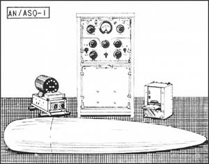
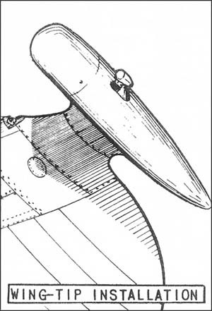
| DESCRIPTION: | Airborne electronic device designed to detect space anomalies in the magnetic field of the earth produced by ships, submarines, accumulations of iron and steel, direct current power-loops, etc. |
|---|---|
| USES: | For detection of submerged submarines and, overland, identification of large industrial areas for bombing through overcast. |
| PERFORMANCE: | These sets indicate proximity to target only. Reliable range depends on the size of the target, its magnetic condition, the heading of the aircraft, and the amount of background or disturbance noise present. Under optimum operating conditions, it is believed that a 750-ton submarine can be detected reliably at distances up to 400 ft. with 4B2 and somewhat farther with the other sets. |
| TRANSPORTABILITY: | Spares (except tubes) for 1000 hrs. operation, with testing equipment and bulk spares for primary maintenance bases, are supplied. No standard size of shipping carton has yet been adopted, but shipment is transportable in cargo planes. |
| INSTALLATION: | Installed weight (including one 35-lb. recording milliammeter) is 250-275 lbs. for 4B2, 145-170 lbs. for AN/ASQ-1 and AN/ASQ-1a, and 210-235 lbs. for AN/ASQ-3. It is sometimes necessary to remove armor plate and guns in order to reduce the magnetic field of the aircraft to usable levels. |
| PERSONNEL: | One operator per set is needed (the navigator, radar operator or rear gunner can be trained for this work.) To maintain the apparatus, it is believed that at least six men per squadron will be required. |
| POWER: | Primary power is 10 to 13.5 amps., 289 volts DC, from plane's supply. |
--106--
AN/CRT-1 and AN/ARR-3 Sono-Radio Buoys
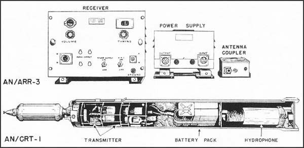
| DESCRIPTION: | AN/CRT-1 is a floating container, incorporating a non-directional hydrophone suspended on a 20-ft. line below the buoy itself, and electronic equipment including a frequency modulated radio transmitter for transmitting the underwater sounds received by the hydrophone to a receiver (AN/ARR-3) in the plane. The buoy transmits on one of 4 frequencies and has a lifetime of about 3 hours before self-scuttling. |
|---|---|
| USES: | For detection of submerged submarines, and verification of MAD contacts as being submarines and not submerged wrecks. |
| PERFORMANCE: | The radio range is approximately 10 miles when the plane is at 300 feet. The underwater range is equivalent to that of any good underwater sound system which may vary from 200 to 3,000 yards depending on the water conditions. No information is provided on the direction of the submarine. |
| TRANSPORTABILITY: | Each buoy weighs 14 lbs. and the receiver, including a dynamotor power supply, weighs 35 lbs. The equipment can be transported by air in the ordinary cargo type aircraft, there being one package for each buoy and two packages for each receiver. The size of the buoy package is 6" x 6" x 48". |
| PERSONNEL: | In normal operations one or preferably two men are required to launch the buoy and to listen on the receiver. |
| POWER: | Supply for buoy itself consists of four 1.5 v "A" batteries, and two 67.5 v "B" batteries. The sono-buoy receiver operates from a supply source of 24 v DC and draws 70 watts. |
--107--
[B L A N K]
--108--
Glossary of Terms
--109--
"A" BAND - The universal IFF Mark III frequency band is designated "A" band by the Navy. (This same band is designated "I" band by the Army.) The Army uses the term "A" band to designate a frequency band used in the Mark II IFF system.
AI -- Abbreviation for Aircraft Interception -- a function of some radar sets.
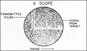
"A" SCOPE -- An indicator on which signals caused by targets appear as vertical deflections on a horizontal range trace. By means of a calibrated scale the approximate range of any target can be read instantly. Approximate azimuth and/or elevation data may be obtained by observing the direction of the antenna when a signal is at maximum intensity. Much more accurate azimuth and elevation data can be obtained by means of pip matching on a modified form of "A" scope. (See PIP MATCHING). It is possible also to get an estimate of the size of targets from an "A" scope. This type scope is often used for tuning up sets and is the basic display in many. The vertical defection shown above at the start of the trace is caused by the transmission of the radar pulses.
ASV -- Abbreviation for Air to Surface Vessel; ASV sets being used in planes for the function of detecting objects on the surface of the sea.
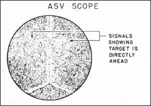
ASV SCOPE -- There is a vertical double "A" scope that is used by some ASV sets and is called an "ASV SCOPE". (This type of indication is not confined to ASV sets, and not all ASV sets use it.) Indicates range of target as well as position of target to right or left or radar-equipped plane. Signals appear as horizontal deflections in the two vertical traces. When the plane is pointed directly at the target, both signals are of equal length. This pip matching is used when homing.
B BAND -- Army designation for a frequency used in the IFF Mark II system.
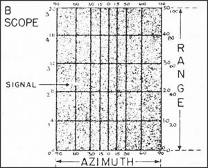
B SCOPE -- An indicator with horizontal and vertical coordinates, giving range vertically; and azimuth, or bearing, horizontally. Signals appear as bright spots.
--110--
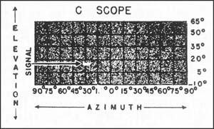
C SCOPE -- An indicator with horizontal and vertical coordinates giving elevation vertically; and azimuth, or bearing, horizontally. Signals appear as bright spots.
EUREKA -- RACON.
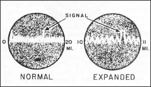
EXPANDED SCOPE -- An arrangement by which a small part of the sweep on an indicator can be spread over a larger area so that a more accurate measurement can be made. Sometimes part of a sweep is expanded on the same indicator; usually part of a sweep on one indicator is made to appear in expanded form (i.e. over a larger area) on a separate indicator.
G BAND -- An Army and Navy designation for a tunable spot frequency band used in the Mark III IFF system. Only fighter planes carry the G band, and it is used in GCI and SCI operations to separate friendly fighters from other friendly or enemy aircraft.
GCI -- Abbreviation of Ground Control of Interception -- a function of some radars, the sets being used to control fighter planes from a ground station.
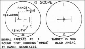
G SCOPE -- A spot error indicator on which a single signal, only, appears as a bright spot from which horizontal wings sprout -- the wings growing as distance to the target diminishes. That is, the shorter the range to the target, the longer the wings. Azimuth is given horizontally, and elevation vertically. The information for moving the spot is obtained by some form of lobe switching arrangement. (See lobe switching).
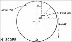
H SCOPE -- A modified B scope. Azimuth is given horizontally, and range vertically. The signal appears as two bright spots, displaced laterally with reference to each other. The slope of the line that can be imagined as joining the dots gives an indication of target elevation. When the line tilts upward (from left to right) the target is upward in relation to the axis of the H-scope-equipped plane. When the line is horizontal, the target is at the same elevation. When the line tilts downward, the target is downward. The H scope is often designated by the term "double dot" scope.
--111--
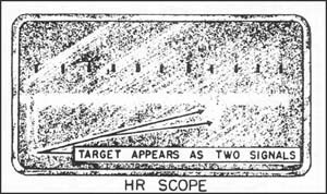
HR SCOPE -- An indicator with a display somewhat similar to an "A" scope. Range is given as on an ordinary "A" scope, and height can be estimated. This is done by having the target appear as two signals by the use of two sets of antennas at different elevation angles, and by estimating the size-ratio of these two signals and referring to a table that converts size-ratio to height. An HR can also be used to estimate the size of the approaching formation of planes.
I BAND -- Army's designation of the universal Mark III frequency band. See A BAND.
IFF -- Abbreviation of Identification of Friend or Foe -- a function of some radars.
INDICATOR -- All radar signals are displayed on the face of a CATHODE RAY TUBE. This face is a flat surface at the end of the tube and is called the INDICATOR, SCOPE, or SCREEN. The word INDICATOR also is used to refer to the whole cathode ray tube, as well as the component of a radar set that houses the cathode ray tube and contains associated circuits. For various types of display afforded by an indicator see A SCOPE, ASV SCOPE, B SCOPE, C SCOPE, H SCOPE, HR SCOPE, J SCOPE, PPI, EXPANDED SCOPE and MOVING SPOT INDICATOR.
INTERROGATOR -- A pulse type transmitter used to challenge transpondors for IFF purposes in an IFF system. The interrogator is part of the interrogator-responsor unit.
IR -- Abbreviation of Interrogator-Responsor. See INTERROGATOR. The IR is the part of an identification system (IFF) which challenges doubtful aircraft or ships and receives and displays the recognition signal.
IRT -- An abbreviation for Interrogator-Responsor-transpondor, when all are combined in a single unit. An IRT system is an IFF device.
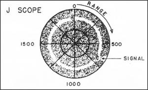
J SCOPE -- Also called CIRCULAR SWEEP SCOPE. It is an A scope with the trace around the outer rim of the face of the indicator, instead of horizontally across the indicator. The signal appears as a radial deflection in the moving trace. Like an ordinary A scope, range data are given, but greater accuracy and simplicity are attained.
JELLYFISH -- See RACON.
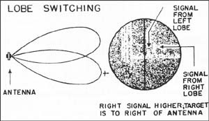
LOBE SWITCHING -- The act of moving the
--112--
lobe of an antenna in space -- the transmitted beam being directed a few degrees to the right and left of (or above and below) the target. Lobe switching is commonly done by either moving one antenna, or else having two antennas. In either case, the direction of maximum intensity of the antenna system is moved so that two signals from these two antenna positions are shown on the indicator -- one signal from each position. To do pip matching the radar operator directs the antenna system until the signals or pips are of equal height -- in which case the antenna is then pointing directly at the target. (See PIP MATCHING). Lobe switching and the resulting pip matching are commonly used to measure azimuth and elevation errors. For example, in the scope picture above, the signal from the right lobe is higher and hence shows that the target is to the right of the antenna. The comparison may also be done electrically, in which case the imperfection of the matching is usually indicated by a meter or by a moving spot indicator.
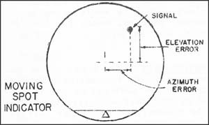
MOVING SPOT INDICATOR -- Also called SPOT ERROR INDICATOR. Used to measure error (departure of target from center line of radar beam) in gun fire control sets. A single signal, only, appears as a bright spot on the indicator. This spot has the same angular relationship to the center of the indicator as the target has to the center of the radar beam. The azimuth error angle appears as the horizontal coordinate; elevation error angle, as the vertical coordinate. If the spot is in the center of the indicator, then the center of the radar beam is pointed directly at the target. This indicator is always associated with some form of lobe switching. The comparison of echo intensities for different directions is done electrically so that a deviation of the spot from center results from any lack of balance in the signal intensities.
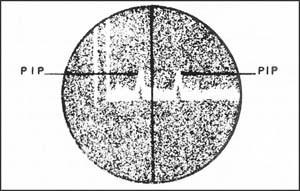
PIP -- A term used to designate the signal on an indicator. Usually the signal is shaped like a triangle, with the base on the line of the sweep -- as in picture of two pips above.
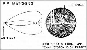
PIP-MATCHING -- A method of accurately determining the azimuth or elevation of a target. Usually the transmitted beam is alternately directed a few degrees to the right and left of (or above and below) the target. A signal, or pip, from each direction appears on the scope. The operator moves the antenna until these double pips are of equal height. The antenna is then pointing directly at the target. Pip-matching is done by lobe switching. (See LOBE SWITCHING).
--113--
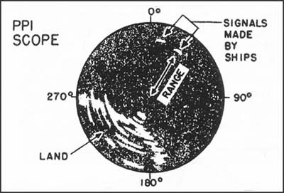
PPI -- Plan Position Indicator. The sweep is a radius on the tube face (from the center to the rim of the tube), and the sweep moves around through 360 degrees. This type of presentation gives the azimuth of the target by the direction of the radial line, and range by the distance of the target's signal from the center point of the tube.
RACON -- Same as RADAR BEACON, RDF BEACON, and RESPONDOR BEACON. A racon is a transpondor used for radar navigation. Radar beacons are divided into several groups: (1) ROOSTER -- An airborne radar beacon which will enable other radar-equipped aircraft to home on it. (2) EUREKA -- A battery-operated lightweight portable radar beacon which may be dropped in a container by parachute. It is interrogated by a Rebecca IR unit. (3) REBECCA -- An airborne interrogator for the Eureka-type beacon. (4) JELLYFISH -- A battery-operated lightweight radar beacon designed to be carried by an aircraft on a bomb rack. It is dropped into the water, moors itself automatically and switches itself on.
REBECCA -- See RACON.
RECEIVER -- Unit of a radar set which amplifies the returning signal and reduces it to the stage necessary for visual representation on the indicator.
RESPONDER -- See RESPONSOR.
RESPONSOR -- A pulse type receiver used to receive from a transpondor the reply to an interrogation in IFF operations. Responsors are invariably used with interrogators, and are a part of an IR unit. Respondors are sometimes termed "responders".
ROOSTER -- See RACON.
SCI -- Ship Control of Interception -- a function of some radar sets, the sets being used to direct fighter planes to an interception course.
SCR -- Abbreviation of Signal Corps Radio, indicating radar set is an Army model. The Navy uses a different designation system for sets.
SPINNER -- Sometimes means REFLECTOR, sometimes means the whole assembly -- reflector, antenna, mount for the reflector, and so on.
TRANSMITTED PULSE -- The signal on the indicator made by the transmitted pulses of energy that are sent out by the transmitter at the start of operations. The way the transmitted pulse (or pulses, since each transmitted pulse appears at the same place on the scope) looks on a scope is shown in the scope pictures in this glossary. See A SCOPE, for an example.
TRANSPONDOR -- A pulse type receiver-transmitter used to receive an interrogating signal and automatically to transmit a reply for reception by a responsor. Transpondors fall into two categories: (a) IFF transpondor -- used solely for identification purposes; (b) Racons (radar beacons) -- used for radar navigation.
--114--
List of equipments by Army-Navy Joint Designation
| AN DESIGNATION | FORMER DESIGNATION | |
| AN/APN-1 | AYF | |
| AN/APN-2 | Mark II Rebecca | |
| AN/APQ-5 | RC-217 | |
| AN/APS-2 | ASG-3 | |
| AN/APS-2a | ASG-2 | |
| *AN/APS-3 | ASD-1 | |
| *AN/APS-4 | ASH | |
| *AN/APX-1 | Mark III Transpondor | |
| *AN/APX-2 | ABJ | |
| AN/ARN-1 | RC-24 or AYD-5 | |
| AN/ARR-3 | Sono-Radio buoy | |
| AN/ASQ-1 | MAD | |
| AN/ASQ-1a | MAD | |
| NA/ASQ-3 | MAD | |
| *AN/CPN-3 | SCR-620 or YK | |
| AN/CRT-1 | Sono-Radio buoy | |
| *AN/PPN-1 | Mark II Eureka | |
| *AN/TPN-1 | Mark II Eureka | |
| *AN/TPS-1 | SCR-602-T3 | |
| *AN/TPS-3 | SCR-602-T8 |
* Available for issue in latter part of 1943.
--115--
[END]
