The Navy Department Library
USS North Carolina (BB55)
Torpedo Damage
Solomon Islands
15 September 1942
CONFIDENTIAL
U.S.S. North Carolina (BB55)
Torpedo Damage
Solomon Islands
15 September 1942
The Chief of Naval Operations directs that this report be shown only to those persons to whom the report would be of value in the performance of their duties.
Steps shall be taken accordingly to insure that this report will be seen by those persons responsible for design, construction and repair of naval vessels, as well as for their operation, but by no others.
Preliminary Design Section
Bureau of Ships
Navy Department
15 February 1949
WAR DAMAGE REPORT No. 61
Printed By U. S. Hydrographic Office
U.S.S. NORTH CAROLINA (BB55)
TORPEDO DAMAGE
15 SEPTEMBER 1942
SOLOMON ISLANDS
15 FEBRUARY 1949
APPROVED
C. L. BRAND
Rear Admiral, U.S.N.
Ass't Chief of the Bureau for Ships
U.S.S. NORTH CAROLINA (BB55)
TORPEDO DAMAGE
15 SEPTEMBER 1942
SOLOMON ISLANDS
| Type | Battleship | Length (O.A.) | 729 ft. |
| Launched | 13 June 1940 | Beam (Extreme) | 108 ft. 3 in. |
| Displacement | 35,000 tons (Standard) | Draft (Before Damage) | Fwd. 32 ft. 6 in. |
| Aft. 34 ft. 8 in. | |||
| Draft (After Damage and counterflooding) | Fwd. 34 ft. 3 in. | ||
| Aft. 33 ft. 9 in. | |||
| Displacement (Before Damage) | 45,280 t. |
References:
(a) C.O. NORTH CAROLINA conf. ltr. L11-1, Serial 0128, of 26 Sept. 1942 (Report of Estimated Damage from Torpedo on 15 Sept. 1942).
(b) BuShips War Damage Report No. 39, dated 15 Jan. 1942 (U.S.S. WASP, CV7, Loss in Action).
(c) Capt. F. P. Sherman sec. ltr. P6-1 (006) of 24 Sept. 1942 (Loss of U.S.S. WASP).
(d) Comdt. NYd., Pearl Harbor conf. ltr. C-L11-1/BB/NY10, Serial Y-02216, of 8 Dec. 1942 (U.S.S. NORTH CAROLINA (BB55) - War Damage Report).
(e) C.O. VESTAL conf. ltr. AR4/L11-1/S94/ (058) of 23 Sept. 1942 (U.S.S. NORTH CAROLINA Torpedo Damage - Report of).
(f) C.O. NORTH CAROLINA sec. ltr. BB55/S81, Serial 0131, of 4 Oct. 1942 (Additional Underwater Protection for the NORTH CAROLINA - Recommendations Regarding).
(g) C.O. NORTH CAROLINA conf. ltr. BB55/S81, Serial 0149, of 19 Oct. 1942 to BuShips (U.S.S. NORTH CAROLINA - Improvement in Underwater Protection of).
(h) BuShips conf. ltr. C-BB55-6/S55 (370) of 10 Dec. 1942 to C.O. NORTH CAROLINA and WASHINGTON (U.S.S. NORTH CAROLINA (BB55) and U.S.S. WASHINGTON (BB56) - Optimum Liquid Loading in Battle Condition).
--i--
CONTENTS
| SECTION | PAGE | ||
| I | FOREWORD | 1 | |
| II | SUMMARY | 2 | |
| III | NARRATIVE | 4 | |
| IV | ESTIMATE OF EFFECT OF DAMAGE ON FIGHTING EFFICIENCY | 6 | |
| V | DISCUSSION | 7 | |
| A. | Type and Size of Torpedo | 7 | |
| B. | Location and Size of Torpedo Hit | 7 | |
| C. | Flooding, Counterflooding and Damage Control | 8 | |
| 1. Liquid Loading before Damage | 8 | ||
| 2. Liquid Loading Immediately After Damage | 8 | ||
| 3. Progressive Flooding | 9 | ||
| 4. Counterflooding and Damage Control | 9 | ||
| D. | Fire | 17 | |
| E. | Structural Damage | 24 | |
| F. | Armor Damage | 25 | |
| 1. General | 25 | ||
| 2. Side Belt | 26 | ||
| 3. Armored Torpedo Protection Bulkhead No. 5 | 26 | ||
| 4. Armored Second Deck | 27 | ||
| 5. Summary of Armor Damage | 27 | ||
| G. | Turret I Damage | 27 | |
| H. | Electrical Damage | 29 | |
--ii--
CONTENTS (Cont'd)
| SECTION | PAGE | ||
| I | Shock Effects | 32 | |
| J. | Piping and Ventilation Damage | 32 | |
| K. | Recommendations of the Commanding Officer | 34 | |
| L. | Recommendations of the Navy Yard, Pearl Harbor | 34 | |
| M. | General Considerations in the Design of the Torpedo Protection System of NORTH CAROLINA | 37 | |
| VI | CONCLUSION | 39 | |
--iii--
LIST OF PHOTOGRAPHS
| NO. | TITLE |
| External Damage and Damage to Torpedo Protection System: | |
| 1. | General view of torpedo damage, port side. |
| 2. | View of hole in shell, looking up and aft. |
| 3. | View of damage to torpedo protection system. |
| 4. | Note bow of torpedo protection bulkheads and rectangular tear in third deck. |
| 5. | Torn scarph in torpedo protection bulkhead No. 4. |
| 6. | Vertical tear in torpedo protection bulkhead No. 3 at frame 46. |
| Damage to Side Armor: | |
| 7. | Top of side armor belt, looking aft. Note that space between shell and side belt has opened. Concrete backing for belt has crumbled. |
| 8. | Another view showing relative movement between shell and top of armor belt at frame 39. |
| 9. | Forward end of armor belt. |
| 10 | Diagonal cracks in armor plate. |
| 11. | Diagonal cracks in armor plate. |
| 12. | Note damage to shell caused by pull of armor bolt. |
| Damage to Armored Torpedo Protection Bulkhead No. 5: | |
| 13. | Note open vertical seam at frame 45 in torpedo protection bulkhead No. 5. View looking aft in A-412V on first platform deck. |
| 14. | Note belly in torpedo protection bulkhead No. 5. View in electrical booth A-416E looking forward. First platform deck is crushed. |
| 15 | Connection of bulkhead 49 to torpedo protection bulkhead, and vertical seam in torpedo protection bulkhead have opened up. Horizontal seam in torpedo protection bulkhead at first platform deck and connection of bulkhead to deck opened up. |
--iv--
LIST OF PHOTOGRAPHS (Cont.)
| NO. | TITLE |
| 16. | Note opening between torpedo protection bulkhead No. 5 and the first platform deck, and between that bulkhead and stiffener at frame 47. |
| 17. | Connection of bulkhead 47 to torpedo protection bulkhead No. 5 between second platform deck and third skin. |
| 18. | Opening between torpedo protection bulkhead No. 5 and the second platform deck, and between that bulkhead and bulkhead 47. |
| 19. | Opening between torpedo protection bulkhead No. 5 and bulkhead 49, and in the vertical seam of torpedo protection bulkhead No. 5. |
| 20. | Torpedo bulkhead No. 5 pulled away from bulkhead 47 and third skin shelf. |
| 21. | View of opposite side of bulkhead 47 to that shown in Photo 20. |
| Structural Damage in Way of, and Behind, Armored Torpedo Protection Bulkhead No. 5: | |
| 22. | First platform deck crumpled by impact of torpedo bulkhead No. 5 in A-412V, looking aft. |
| 23. | Area of crumpled first platform deck in A-412V, looking forward. |
| 24. | Wrinkle in first platform deck as seen from A-508V. |
| 25. | Vertical seams in torpedo bulkhead No. 5, and between that bulkhead and bulkhead 49, opened up. |
| 26. | Opening between bulkhead 49 and torpedo protection bulkhead No. 5. |
| 27. | One of four angles in the connection between torpedo protection bulkhead No. 5 and first platform deck torn. |
| 28. | Damage in A-422M, looking forward. |
| Damage to Powder Circle, Turret I Lower Handling Room and Ordnance Storeroom A-616A: | |
| 29. | Blanked-off ventilation valve at frame 46 on port side of powder circle outer bulkhead (turret stool) just below first platform deck level. Leakage was carried by trough and drained to pump room bilges. |
| 30. | Stiffener on turret stool fractured. Stool pushed in at and below first platform shelf. |
| 31. | View of fractured stool stiffener, looking forward. |
--v--
LIST OF PHOTOGRAPHS (Cont.)
| NO | TITLE |
| 32. | Bulge in Turret I lower handling room stationary deck. |
| 33. | Damaged beam at frame 45 in A-616A. |
| Damage on Second Deck: | |
| 34. | Buckled bracket of beam under second deck at frame 51. |
| 35. | Wrinkled metal joiner bulkhead in officer's stateroom on second deck, port. |
| 36. | Stiffener on bulkhead 49, second deck, port. Dent in flange near tangency bracket and crack in flange. |
| Damage to Third Deck | |
| 37. | View looking outboard and aft into A-320A showing large section of third deck plating torn and blown upward. |
| 38. | Section of third deck torn from shell, ripped transversely and pushed upward. |
| 39. | Forward transverse tear in third deck in A-320A. |
| Additional Damage on Third Deck: | |
| 40. | >Buckles in third deck and in frame 51 bracket in storeroom A-324A |
| 41. | Buckle in third deck in storeroom A-324A. |
| 42. | Damage to bulkhead 49 and to third deck in A-324A. |
| 43. | Inboard bulkhead of A-314A, looking aft. |
| 44. | View looking forward in passage A-316T. |
| Damage to Third Deck Passage A-316T: | |
| 45. | View looking forward from frame 49 in passage A-316T showing outboard bulkhead pushed inboard. |
| 46. | View looking aft to frame 46 in passage A-316T. |
| Shoring: | |
| 47. | View in A-326-1L looking outboard to port showing shoring of door 3-49-6 leading into A-316T. |
| 48. | Inboard end of shoring shown in Photo 47. Door 3-49-2 shown in picture leads into trunk A-322T. |
--vi--
LIST OF PHOTOGRAPHS (Cont.)
NO. |
TITLE |
| 49. | Door 3-39-2, leading into crew's washroom A-312L from crew's W.C. A-310-1L, shored. |
| 50. | Shoring of inboard bulkhead of magazine A-422M in magazine A-420M, looking outboard to port. |
| 51. | Shoring of door 5-51-2, leading from A-514M to A-516M, looking outboard to port. |
| 52. | Shoring of cofferdam around doorway into passage A-316T from A-310-1L, looking aft and to port. Black area in door frame is a rubber gasket on the cofferdam. |
| 53. | One of two portable submersible pumps in starboard side of A-310-1L with discharge hose leading to ventilation trunk and from thence to a ventilation opening in the second deck at frame 44, starboard. |
| 54. | Yoke fitting joining the discharge hoses from the two submersible pumps rigged in A-310-1L. Deck connection is watertight fitting for discharge line of the port submersible pump in A-310-1L. Fire hose from Yoke fitting leads aft taking water to an isolated firemain riser. On the main deck a hose carried the water from the fireplug to the waterway. |
| Shock Effects: | |
| 55. | Bent frame, missing struts and broken supports of search radar. |
| 56. | Broken starboard supports on rear of search radar. |
| 57. | Frame and rear leg of right hand desk in radio room sagged. |
| 58. | High pressure air valve torn from piping on outboard bulkhead of powder circle. |
--vii--
LIST OF PLATES
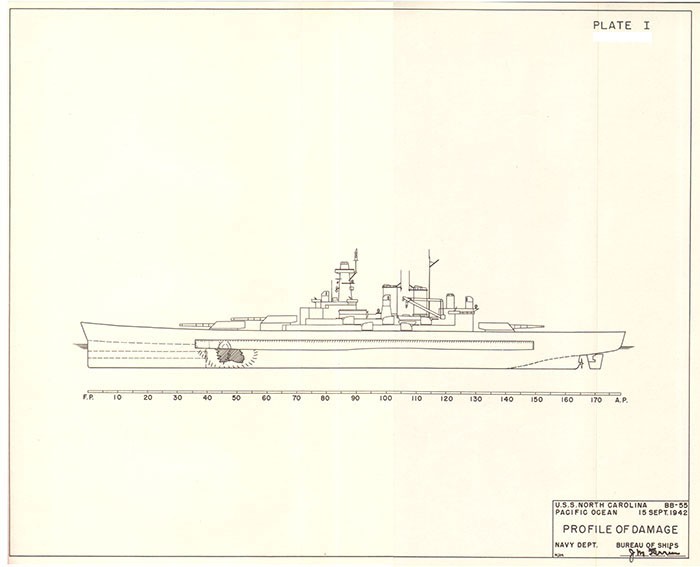
| I | Profile of Damage (Port Side) |
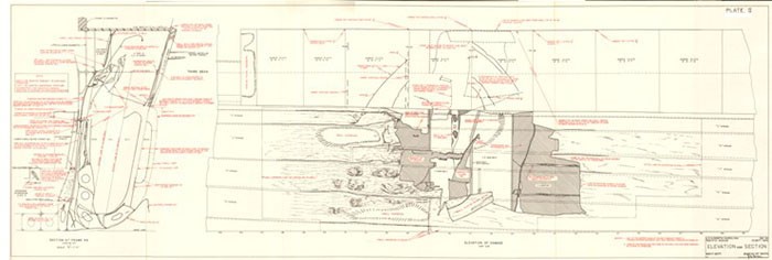
| II | Elevation and Section (of Damaged Structure) |
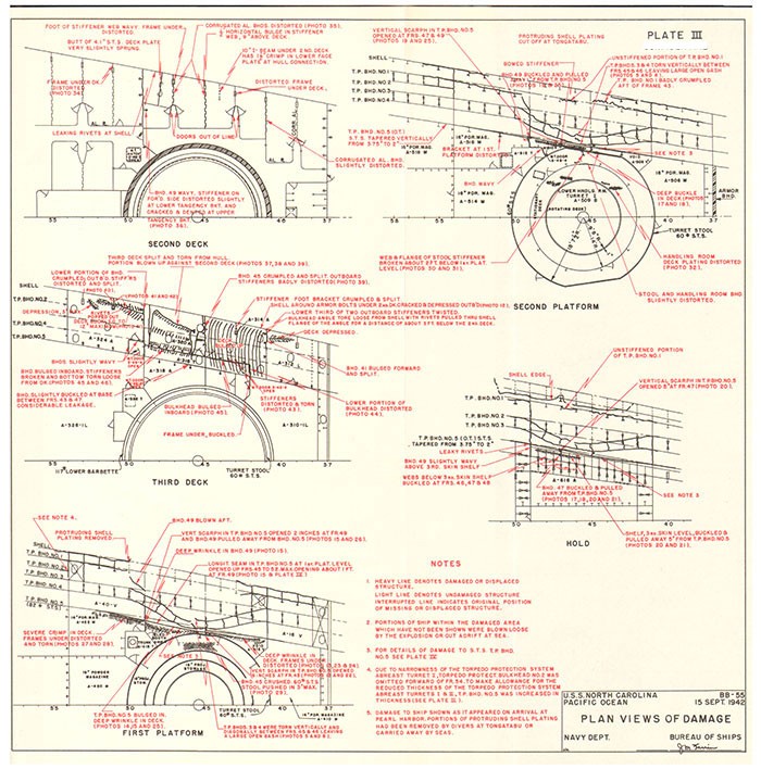
| III | Plan Views of Damage (2nd, 3rd, 1st PL, 2nd Pl. Decks & Hold) |
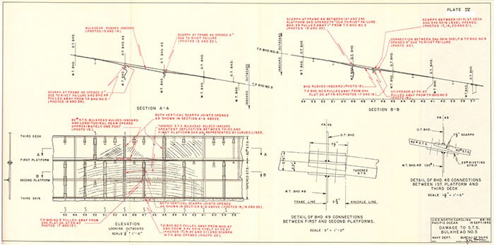
| IV | Damage to S.T.S. Bulkhead No. 5. |
| V | Flooding Diagram |
--viii--
SECTION I - FOREWORD
I-1. NORTH CAROLINA was damaged by a submarine torpedo which struck the port side abreast No. I Turret. The holding bulkhead failed and permitted limited flooding inboard. The torpedo protection system in way of the hit is thinner than amidships as necessitated by the speed characteristics. Abreast Turret I there is one less torpedo protection bulkhead and, therefore, one less torpedo protection layer on either side of the ship. The Bureau has given consideration to the addition of blisters and to certain recommendations for increased underwater protection. Blisters have not been added principally due to their adverse effect on speed.
I-2. The ship was not at General Quarters when hit. Speed was immediately increased from 19 to 25 kts. The 5 1/2° list was removed within six minutes. Turret I remained operable. The flooding, although extending inboard of the holding bulkhead and above the third deck, was not extensive. Progressive flooding was minor. Loss of life was small. No fires occurred as a result of the flash. There was no machinery damage, and shock effects were not severe.
I-3. It is considered that the ship's force handled the casualty in a very efficient and businesslike manner and that the ship generally absorbed the damage without serious effect or marked loss in fighting efficiency. It is believed that continued effort should be directed in new large ship design to prevent failure of the holding bulkhead.
I-4. This report is based upon the war damage reports from the ship and the repair activities. The PLATES were prepared by the Bureau from sketches, plans and photographs.
--1--
SECTION II - SUMMARY
II-1. At 1452 on 15 September 1942, while operating as a unit of Task Force 17, NORTH CAROLINA was hit by a submarine torpedo. The torpedo detonated abreast Turret I at about frame 46, port, two feet below the lower edge of the armor belt.
II-2. General Quarters was sounded and Condition ZED set. Speed was increased from 19 to 25 kts. A 5 1/2° port list was removed in six minutes by counterflooding. The ship maintained station for five hours and then was directed to proceed to port for temporary repairs by tender.
II-3. Structural damage was of average amount. The hole in the shell was 36 ft. long. It extended from the foot of torpedo protection bulkhead No. 5 to the bottom edge of the side belt. Torpedo protection bulkhead No. 1 was demolished between frames 46 and 50, and torpedo protection bulkheads 3 and 4 were forced inboard and torn. Vertical and horizontal seams in armored torpedo protection bulkhead No. 5 were opened up and several compartments inboard of this bulkhead were flooded. An area of the 30 lb. S.T.S. third deck was blown upward to the overhead in A-320A. The first and second platform decks and third skin shelf were crushed abreast the hit. The turret stool was indented slightly. There was some minor deformation of Turret I lower handling room deck and framing beneath.
II-4. Flooding was not extensive and progressive flooding, limited. List and trim were quickly removed by counterflooding.
II-5. There was no fire. Flash from the torpedo was reported in the lower handling room of Turret I and in other spaces. It produced no damage. Whether the flash could have produced a smokeless powder fire or explosion, had there been exposed powder charges, is problematical.
II-6. Damage to armor, except for torpedo protection bulkhead No. 5, was inconsequential. Several plates of the side belt were partially cracked and pushed inward at the bottom. Seams of armored torpedo protection bulkhead No. 5 opened up as described above. The second deck was buckled slightly upward.
II-7. Damage to Turret I was not severe. Burrs on the training pinion and rack were removed by ship's force. Stool indentation was local and of small amount. About two feet of water entered the lower handling room through a vent duct. Power circuits were not affected, although it was reported that some seepage into A-615T caused saturation of the lower ends of cables leading down the turret center column.
II-8. Electric power and lighting circuits and equipment were damaged in flooded spaces. Shock damage to electric equipment was slight and shock damage, in general, was not serious. Miscellaneous piping and ventilation damage occurred in way of the hit.
II-9. After temporary repairs by VESTAL at Tonga-Tabu, NORTH CAROLINA proceeded to Pearl Harbor Navy Yard for permanent repairs.
--2--
II-10. All factors considered, it is believed that NORTH CAROLINA's power of survival was not severely strained by the torpedo hit, and that the effect of the damage on her fighting efficiency was limited. Sustained speed was reduced to about 18 kts. according to reference (a), although speeds up to 24 kts. could be made. Radius was reduced by loss of 150,000 gallons of oil. Although flooding occurred through the holding bulkhead, overall flooding was not extensive. Turret I apparently was still able to fire.
--3--
SECTION III - NARRATIVE
III-1. On the afternoon of 15 September 1942, NORTH CAROLINA was operating as a unit of Task Force 17, in company with Task Force 18. The two Task Forces were on base course 280° true, zig-zagging according to plan. Visibility was about 20,000 yards; sea, moderate with many white caps; and the weather was fair. WASP (TF18) was duty carrier and conducted flight operations every two hours, turning into the wind on course about 130 true; the HORNET group (TF17) conformed. When a radical change of course was made, as was necessary on this date, to head into the wind from the base course or to resume the base course after flight operations, considerable time elapsed after each change before the destroyers attained their new screening stations.
III-2. At 1218, an enemy four-engine seaplane was shot down by a WASP plane about fifteen miles to the westward of the formation. At 1419, Task Force 17 turned into the wind, course 130°, speed eighteen knots, conforming with the movements of WASP. At 1444, HORNET turned right to base course 280°, and WASP was seen on fire and smoking heavily. It was subsequently learned that WASP had been torpedoed. At about 1450, LANSDOWNE (TF18) reported by TBS: "Torpedo passed directly under 86 (LANSDOWNE) coming directly for FORCE, course 080°." This destroyer was approximately six miles away.
III-3. At about 1450-30, while NORTH CAROLINA was starting to swing right from course 280° true in conformity with HORNET which had been observed to start turning right, MUSTIN (TF17) reported by TBS: "Torpedo passed astern headed for you." When this report was received by NORTH CAROLINA, MUSTIN bore about 60° on the port bow, distant about 1200 yards, apparently regaining screening station for the base course. The order, "Right full rudder. Emergency flank speed." was given immediately.
III-4. At 1452, while turning right on course approximately 295° true and making R.P.M's for 19 kts., a torpedo struck NORTH CAROLINA at about frame 46 port and detonated on impact. The torpedo was not seen from the ship until just before it struck. The ship was in Material Condition Red Yoke, a modification of Condition Yoke, which permitted use of washrooms and ventilation in living spaces. General Quarters was sounded immediately and Condition ZED set. Speed was increased to 25 kts.
III-5. Only one explosion was noted. It produced a quick sharp detonation and a sharp cracking noise. A flash of flame was reported in Turret I handling room, the access trunk leading from the handling room to the third deck and A-317T. A yellowish-brown smoke (reported by some observers to be light gray) filled every open compartment between frames 37 and 71. A heavy column of oil and water rose approximately to the height of the stacks. One man was washed overboard from the forecastle. No fires resulted from the explosion.
--4--
III-6. The ship listed to port about 5 1/2° and trimmed by the head. Orders were issued to the Damage Control Station to remove the list and trim, and this was accomplished by 1458. The ship left a very heavy oil slick.
III-7. NORTH CAROLINA maintained station with Task Force 17 until 2000 at which time CTF17 directed her to proceed to Tonga-Tabu with ANDERSON and DALE as escorts.
III-8. At 1930 five men were reported missing: one washed overboard, one last seen in washroom A-310L, which was flooded, and three in A-316T, immediately adjacent to compartment A-320A. This compartment was located immediately over the explosion and was under air test at the time of the hit.
III-9. On 19 September, NORTH CAROLINA anchored at Nukualofa, Tonga-Tabu where VESTAL made the following repairs:
(a) Removed protruding lips of shell plating by underwater cutting in way of hole made by torpedo.
(b) After trimming the ship seven feet by the stern, installed a cofferdam around starboard door and then pumped out A-310L for the removal of four bodies and for repairs to pipe lines and bulkhead boundaries to prevent further flooding.
(c) Provided additional shoring for bulkheads adjacent to flooded areas.
After completion of these repairs on 21 September, the Commanding Officer reported the ship capable of a sustained speed of 18 kts. and a maximum speed of 24 kts. for short periods only, due to the stress against shored bulkheads.
III-10. NORTH CAROLINA then proceeded to Pearl Harbor Navy Yard for accomplishment of permanent repairs.
--5--
SECTION IV - ESTIMATE OF EFFECT OF DAMAGE ON FIGHTING EFFICIENCY
IV-1. Reference (a) estimated that the fighting efficiency of the ship was affected as follows:
(a) Sustained speed of the ship reduced to 18 kts., although speeds up to 24 kts. could be made for brief periods without straining the shored bulkheads to such a degree that reduction in speed would be necessary.
(b) Fuel capacity reduced by 150,000 gallons.
(c) Armored protection reduced by:
(1) Water taken into the ship.
(2) Ruptures in No. 5 torpedo bulkhead between frames 43 and 48, port.
(3) Ruptured area of third deck at frame 45, port.
(4) Ruptures in lower boundaries of No. 5 torpedo bulkhead extension above third deck at frame 45, port.
(d) Turret I lower structure weakened so that the turret should be fired only under gravest need.
(e) Considerably increased vibration noted in fire control instruments in Fire Control and forward towers.
(f) Search antenna foundation weakened structurally to such an extent that it would be put out of commission by a relatively slight shock.
--6--
SECTION V - DISCUSSION
V-A. Type and Size of Torpedo
V-A-1. The Commanding Officer reported that NORTH CAROLINA was hit by a submarine torpedo at 1452 (Zone 12 time) and estimated that the warhead weighed 750 to 800 pounds. Reference (b) reported that at about 1445, two submarine torpedoes struck the starboard side of WASP. Reference (c) stated that WASP received three torpedo hits at about 1444 and that a fourth torpedo passed ahead and later passed under LANSDOWNE. Reference (a) stated that LANSDOWNE reported at about 1450 to NORTH CAROLINA: "Torpedo passed astern headed for you." Both references (a) and (c) stated that no enemy contacts had been made during the day except one Japanese four-engine patrol plane which had been shot down by a WASP plane at about 1218.
V-A-2. The two most frequently used Japanese submarine torpedoes contained 450 and 660 pounds of Shimose, respectively. The damage to NORTH CAROLINA indicates a charge approximating the 660 pound charge of Shimose (picric acid) used in the Type 89 Japanese submarine torpedo.
V-B. Location and Size of Torpedo Hit
V-B-1. Based on inspections made by VESTAL divers, it was estimated that the torpedo struck at frame 45-46, port, 10 ft. 4 in. below the armor belt or 20 ft. 4 in. below the waterline. The dimensions of the hole in the ship's hull as reported by the divers were: length (fore and aft), 32 ft., width (depth), 18 ft. The top of the hole was reported to be approximately 16 in. below the lower edge of the armor shelf; the center, approximately 20 ft. 4 in. below the 33 ft. 7 in. waterline; and the length, from frame 43 to frame 51. The area of serious indentation of the hull was estimated to be from frame 42 to frame 53, from the level of the first platform deck to a level approximately halfway between the second platform deck and the hold.
V-B-2. Examination of the damage in drydock at Pearl Harbor indicated that the torpedo struck the shell on the port side, about one foot forward of frame 46 and two feet below the bottom of the side armor. The Navy Yard reported that there was a possibility that the torpedo penetrated the 20 lb. plate of the shell before exploding, because the ragged edges of the shell plating where not removed by underwater cutting were bent outboard. VESTAL report, reference (e), stated that projecting portions of damaged plating and stiffeners were cut off, and indicated the projecting or overhanging lips in a sketch. Pearl Harbor Navy Yard further reported that of the torpedo damages examined to date of report by that activity, this case was the second occurrence of this phenomenon, the other instance being the torpedo hit sustained by SARATOGA on 31 August 1942.
--7--
V-B-3. It has been found from both war experience and model tests that with a liquid-backed shell the damaged plating will usually be turned inboard. With an air-backed shell, the damaged edges of plating will generally be turned outboard. NORTH CAROLINA's shell plating was air-backed. Outward turned shell plating increases resistance to propulsion (resulting in loss of speed) and increases the probability of extension of damage by tearing the plating.
V-B-4. Drydock inspection showed that the shell plating was completely demolished from frame 43 to frame 52 between the armor and the turn of the bilge. Distortion and indentation of the shell plating extended forward to frame 37, aft to frame 58, down to the foot of torpedo protection bulkhead No. 5, and upward to the top of "M" strake (PLATE II).
V-C. Flooding:, Counter flooding and Damage Control
1. Liquid Loading before Damage
(Plate V)
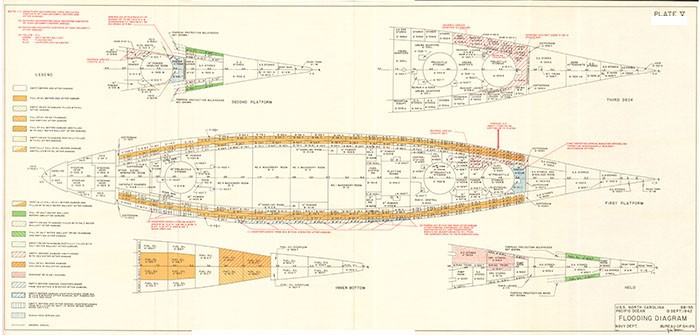
V-C-1. The voids in the damaged area were empty prior to the detonation. The void layers were the outer and inner layers of the four-layer underwater protection system. The two fuel oil layers, as well as the bottom fuel oil tanks in the vicinity of the damaged area, were full of oil at the time of the explosion. Forward of frame 37, A-14F was filled with ballast, and A-908F and A-12F were empty. The total weight of liquid in the damaged area prior to damage was 597 tons.
V-C-2. At the time of the design of NORTH CAROLINA, the liquid loading (AWWA) was selected to minimize the damage to the holding bulkhead. Since that time, the conviction has become established that, in most cases, there is a greater net gain in reducing list after damage, by carrying the outer two layers full, than loss in the slightly increased damage to the torpedo protection system. Extensive piping changes would be necessary to permit carrying the outboard layer in NORTH CAROLINA full. Since this Class has good transverse stability characteristics, the increased angle of heel after damage, by reason of the outer layer being void, has been accepted.
2. Liquid Loading Immediately after Damage
(Plate V)
V-C-3. As a result of the damage, the following compartments and tanks flooded or were opened to the sea immediately:
--8--
| Voids | Fuel Tanks | Magazines | Storerooms | Trunks | Living Space |
| A-16V | A-12F | A-422M | A-314A | A-316T | A-310-1L |
| A-22V | A-14F* | A-516M | A-318A | A-317T | A-312L |
| A-24V | A-18F* | A-320A | A-416E | ||
| A-30V | A-20F* | A-324A | A-418T | ||
| A-32V | A-26F* | A-328A | A-510E | ||
| A-38V | A-28F* | A-512T | |||
| A-40V | A-34F* | ||||
| A-46V | A-36F* | ||||
| A-54V | A-42F* | ||||
| A-308V | A-44F* | ||||
| A-408V | A-50F* | ||||
| A-412V | A-52F* | ||||
| A-508V | A-910F* | ||||
| A-612V | A-912F* | ||||
| A-618V |
The total weight of liquid added in the damaged area as a result of damage was 970 tons.
3. Progressive Flooding
(Plate V)
V-C-4. The extent of slow flooding was negligible. The following compartments were partially flooded by seepage from flooded compartments:
A-615T
A-616A
A-624A
4. Counterflooding and Damage Control
(Plate V)
V-C-5. A-615T, A-616A and A-624A were pumped dry by portable submersible pumps after a few inches of water had accumulated in each compartment. Flooding would not have occurred in A-615T had the drain to No. 2 Pump Room been adequate. Water rose in this trunk until the lower ends of the power cables leading down the center column of Turret I were saturated with oil and water. The ship recommended a 50 per cent increase in the size of the drain.
V-C-6. Following the explosion which occurred at 1452, the ship listed to port and trimmed slightly by the head. The Damage Control Station was ordered to remove the list and trim. This was accomplished by 1458. The voids listed below were partially counterflooded immediately following the explosion:
| A-87V | B-49V |
| R-13V | R-59V |
| B-23V | B-67V |
| B-31V | B-77V |
| B-41V | B-85V |
__________
* Filled with fuel oil or ballast before damage.
--9--
Counterflooding was stopped as soon as the ship returned to an even keel. Time required to return the ship to zero list, from the time of detonation of the torpedo, was approximately six minutes. It was estimated that 480 tons of counterflood water was taken on board in the above voids.
V-C-7. Soon after the damage, it was possible to pump overboard 144 tons of contaminated oil and to transfer the remaining uncontaminated oil from the damaged area to the starboard side. This permitted the three forward counterflooded voids, A-87V, B-13V and B-23V, to be emptied.
V-C-8. Later on the same day voids, C-11V, C-13V and C-17V, were flooded and the remaining seven counterflooded voids, B-31V, B-41V, B-49V, B-59F, B-67V, B-77V and B-85V, were emptied.
V-C-9. The following shoring was accomplished soon after the damage was received:
(1) Door 3-49-6 leading to A-316T from A-326-1L.
Shoring in A-326-1L (Photo 47).
(2) Door 3-49-2 leading to A-322T from A-326-1L.
Shoring in A-326-1L (Photo 48).
(3) Inboard bulkhead of A-324A in A-326-1L (Photo 47).
(4) Door 3-49-5 leading to A-317T from A-326-1/2L.
Shoring in A-326-1/2L.
(5) Door 3-39-2 leading to A-312L from A-310-1L.
Shoring in A-310-1L (Photo 49).
(6) Door 4-48-2 leading to A-416E from A-418T.
Shoring in A-418T.
(7) Door 4-48-4 leading to A-422M from A-418T.
Shoring in A-418T.
(8) Forward bulkhead of A-422M in trunk A-418T.
(9) Inboard bulkhead of A-422M in A-420M (Photo 50).
(10) Forward bulkhead of A-508V in compartment A-506M.
(11) Inboard bulkhead of A-512T in compartment A-514M.
(12) After bulkhead of A-516M in A-518M.
(13) Inboard bulkhead and door of A-516M in A-514M. (Photo 51).
(14) A-62V was flooded to shore its forward bulkhead at frame 59.
--10--
Additional damage control measures effected after arrival on 19 September at Nukualofa, Tonga-Tabu were:
(1) By transferring oil and water and flooding voids in the after part of the ship, a trim of seven feet by the stern was obtained. This reduced the height of water and oil in A-310L and A-328A sufficiently to make feasible the use of cofferdams around their doors, which were then opened and suction hoses led in. These compartments were then pumped dry and entered. Such leaks as those around bulkhead boundaries, from deck drains, urinals, stools, etc., were caulked or blank flanged. Two damaged doors in A-310-1L were removed and watertight cofferdams substituted (Photos 49 and 52). Two portable electric pumps were then rigged in this compartment and their discharge hoses were led through vent ducts to an isolated firemain riser on the second deck (Photos 53 and 54). Passages through the second deck were flanged watertight. After the ship was returned to normal trim and while proceeding to Pearl Harbor, it was found that 15 minutes pumping per watch kept this area dry. Personnel then returned to A-326L which had been vacated.
(2) All shoring was inspected and reinforced as necessary.
(3) A diver from VESTAL inspected the hole in the ship's side and cut off protruding lips, as indicated in Plate II.
V-C-10. Chapter 88, BuShips Manual states that for ships with torpedo protection systems (underwater protection systems), counterflooding should be undertaken as soon as clinometers and reports give evidence of a list developing from torpedo attack. NORTH CAROLINA's action in immediately removing the list was in agreement with the present policy of the Bureau. The Manual further states that, for ships with torpedo protection systems, the over-all ship survival measures in the order of their importance are:
Step 1. Counterflood.
Step 2. Restore reserve buoyancy:
(a) By pumping damage water overboard.
(b) By transferring fuel oil across the ship and pumping out the counterflooding water.
Step 3. Correct trim:
(a) By pumping damage water overboard.
(b) By transferring fuel fore-and-aft.
(c) By pumping liquids overboard from intact tanks at the low end.
--11--
V-C-11. Thus, for ships with underwater protection systems, it is to be noted from the above paragraph that:
1. List removal is of prime importance, restoration of lost reserve buoyancy is of next importance and finally, trim correction is of third importance.
2. List correction is of such great importance that it should be undertaken as soon as list develops and in spite of the fact that the means selected for list removal (i.e. counterflooding) might result in reducing the total number of torpedo hits on both sides that the ship might ultimately survive, and in spite of the reduction of the effectiveness of the underwater protection system in the event that the void layer immediately outboard of the holding bulkhead were counterflooded.
3. List correction is so important that it should be accomplished by counterflooding (Step 1.) even though Step 2. directs restoring reserve buoyancy by pumping out the counterflood water as soon as possible after counterflooding. This means simply that list removal is so necessary that it is worthwhile accepting the extra labor of deliberately taking counterflood water onboard and the several disadvantages of counterflood water, and then pumping the same water overboard immediately thereafter, as soon as damage water can be removed or as rapidly as fuel oil (or ballast water) can be transferred across the ship or pumped overboard.
V-C-12. Any list removal policy or instructions must support the basic precept of maximizing the protective resistance of the ship and prolonging her life. The policy and instructions must meet the conditions of expected attack. Torpedoes may strike singly or severally, simultaneously or intermittently, on one side or both sides and variously distributed with regard to the ship's length. For one or more hits on one side, whether received simultaneously or otherwise, list removal by counterflooding should begin immediately after the list has become manifest. For a preponderance of hits on one side, where hits are received simultaneously, list removal by counterflooding should likewise begin immediately. For equal numbers of hits on each side, when received simultaneously, the hits would very likely balance, and little, if any, list removal would be necessary. For the case where hits are received on both sides, where there is a time interval between the hits on one side and the hits on the other side, immediate counterflooding may reduce the maximum number of hits the ship can ultimately survive, but at the same time the immediate counterflooding would prolong her life beyond the number of hits received initially. In this last case, in other words, the counterflood water might reduce the ultimate number of torpedo hits that the ship could survive, but might prevent the loss of the ship from the number of torpedo hits already received. Again, in this last case, it is more important to have the ship survive a given number of hits already received than to maximize the number of hits the ship might ultimately receive. For protection against under bottom hits, the principal protection of the ship is watertight subdivision (small compartments) with bottom compartments symmetrically located with regard to the ship's centerline, and the ship's longitudinal strength.
--12--
V-C-13. The severest underwater attack is that of multiple simultaneous side contact torpedo hits. OKLAHOMA capsized after receiving several torpedo hits on one side during an interval of a few minutes. In order to counter the case of simultaneous plural attack on one side, rapid and extensive means of list removal must be provided. Such attack can be expected in future war, particularly by submarines.
V-C-14. As a general principle, it is considered that after given amounts of damage, the remaining stability should match the remaining reserve of buoyancy and that the rate of depreciation of overall stability for increasing amounts of damage should match the rate of loss of reserve buoyancy. The designer, as well as the operating personnel, is confronted, however, with the fact that amounts of damage water, producing relatively small loss in reserve buoyancy, may seriously reduce overall stability. Further, it may be stated that amounts of damage water, producing a relatively small loss in reserve buoyancy, may produce a heavy list.
V-C-15. The principal purpose of the underwater protection system, as stated above, is to protect the vitals. Its liquid loading must contribute to its principal function, but at the same time, should be so chosen as to produce the minimum list after damage. From the stability standpoint, the outstanding feature of the torpedo protection system is the inherent source of listing moment contained in the void layers. Hence, to protect the vitals, an underwater protection system is developed whose series of void and liquid layers is essential to the protective system, but whose voids constitute a source of unsymmetrical flooding. Whenever an underwater protection system is attacked on one side of a ship, therefore, a list develops.
V-C-16. List produces many deleterious effects on the ship and may threaten survival. Loss of the ship by capsizing is the end result of uncontrolled list. Loss of a ship by bodily sinkage, resulting from loss of buoyancy, occurs much less frequently than by capsizing or plunging. List threatens survival by reducing transverse stability and by interfering with normal and emergency measures of the operating personnel. Not only does list involve reduction of transverse stability with reduced freeboard on the damaged side, but also exposes the bottom and the high deck levels with no torpedo protection to contact torpedo attack, and further, may permit progressive flooding from damaged compartments into adjacent compartments through non-tight, high subdivision. List involves interference with flight operations, impaired armament, machinery casualty, reduced speed and maneuverability, access difficulties, etc.
V-C-17. The Bureau's objective in recommending liquid loadings is to place the ship and keep the ship in a condition of maximum resistance to underwater attack. In determining the liquid loading of the underwater protection system, one of the controlling criteria is to keep the heel after damage as small as possible. It is desired to keep the heel after damage a minimum not only for the compelling reasons outlined above, but also to minimize the amount of counterflooding required to neutralize the list. It is desirable to take all practicable steps before damage to insure against large angles of heel after damage and to keep to a minimum the amount of counterflood water required to remove given amounts of list.
--13--
V-C-18. The need for a means of rapid list removal has been firmly established. War experience demonstrated that, in the majority of cases of the last war, correction of list was a relatively slow process. War experience demonstrated the need for rapid list removal in such cases as multiple torpedo hits on one side of a battleship or large carrier, or possibly, where a preponderance of hits occurred on one side. Where the hits occurred on both sides of the ship, there was less need for rapid list correction. In cases where the hits on both sides of the ship balanced, rapid list removal by counterflooding was undesirable.
V-C-19. In a large ship with an underwater protection system there are at least three practical means of list correction: (1) Flooding from the sea (counterflooding), (2) Pumping liquid overboard, and (3) shifting liquids onboard. Flooding from the sea to correct list or trim reduces the reserve buoyancy. Once lost, reserve buoyancy is difficult to regain. In case of further damage, counterflooding may reduce the total number of hits that the ship can survive. Flooding of the void layer immediately outboard of the holding bulkhead reduces its effectiveness in resisting further attack. Hence, from the standpoint of producing the minimum adverse effects on the ship, and disregarding the urgency of list removal, it would be desirable to remove list first, by removing damage water or liquids from the damaged side; second, by shifting liquids already onboard, and lastly, by taking liquids onboard.
V-C-20. List removal by pumping liquids overboard or by pumping liquids from side to side is a relatively slow process. Sometimes there are no empty tanks into which liquids already onboard can be pumped. Counterflooding, in spite of its adverse effect on buoyancy, and its other adverse effects, is a rapid means of list removal. The necessity for quick list removal and the margin of reserve buoyancy over residual stability after damage are sufficient to overbalance the disadvantages of deliberately taking water into the ship. Consequently, counterflooding must be looked upon as the first means to use and the principal means in list control on ships with an underwater protection system.
V-C-21. The limiting amount of counterflooding that can be introduced after damage in any given ship with an underwater protection system should be that amount which will prevent capsizing up to the point that the total reserve of buoyancy has been exhausted. It would appear then, that in a new design, not only should all void layers of the underwater protection system be fitted for rapid flooding, but flooding of compartments having an off-center moment should be considered. The order of counterflooding would be, therefore, the outer void layers of the underwater protection system, then the void layer outboard of the holding bulkhead, finally in extremis, the spaces inboard of the holding bulkhead having an unsymmetrical moment.
V-C-22. The efficacy of counterflooding in list removal in regaining freeboard is not without limitation. For instance, in the case of PRINCE OF WALES, two or possibly three hits were received on the port side. The liquid loading, subdivision and stability were such that the ship took a very large heel - something over 20°. It was found
--14--
impossible to operate any machinery or to effect any counterflooding. The ship lay dead in the water until hit by about four more torpedoes on the starboard side which caused her loss. In the case of BARHAM, which received four torpedo hits on one side, the liquid loading, subdivision and stability were such that she rolled over on her beam ends. She lay in that position about four minutes before a magazine exploded and caused her final destruction. These cases emphasize the importance in the design of the ship for limiting the list after extensive damage and also of maintaining the prescribed liquid loading during operation for minimizing list after damage. With regard to regaining freeboard by counterflooding, studies have indicated that on certain ships, MARYLAND for instance, the gain in freeboard over that in the damaged and listed condition is likely to be small or of insignificant amount. However, after returning the ship to an even keel by counterflooding, the residual freeboard to the main deck at the side may be only slightly greater than when the ship was in the listed condition following damage, but there is a very important gain in operability and overall stability as the ship regains an even keel.
V-C-23. With regard to the present philosophy and instructions for rapid list removal by counterflooding as outlined in Chapter 88 BuShips Manual, it is desired to emphasize the importance of the liquid removal and transfer systems. Removal of the list is vital and is the first overall ship survival measure to be carried out after damage, and it is to be carried out by a rapid means - counterflooding; but once the list has been promptly removed by counterflooding, the ship is no longer in its condition of greatest resistance against further attack. Restoration of lost reserve buoyancy is immediately desirable. This is attained entirely by use of the liquid removal and transfer systems. Therefore, it is pointed out that not only is the provision of a means for rapid list removal necessary for reducing the effects of damage already received, but also the provision of a ballasting system of adequate capacity is a vital corollary.
V-C-24. It is to be noted from the above discussion that trim correction is considered, generally speaking, of secondary importance to list correction in ships with underwater protection systems. Such ships are very large. Large carriers, in particular, and modern battleships possess large reserves of buoyancy and freeboard. Large shifts or changes in weight cause relatively small changes in trim. Trim is not apt to be fatal unless the sea is washing over the weather deck.* Increase in freeboard at the damaged end is difficult to attain by counterflooding and is more effectively and quickly attained by removal of liquids from the damaged end. However, the diagonal principle of counterflooding not only fulfills its major function of list removal, but also somewhat improves trim in the cases where ships are hit at their ends.
____________
* In the case of PENNSYLVANIA (8/12/45), for instance, an old ship with low freeboard aft, severe trim by the stern very nearly proved fatal. The fantail was almost submerged following a single torpedo hit aft.
--15--
V-C-25. In any such discussion as the foregoing, the increasing probability of torpedo hits or near-misses under the bottom must not be lost sight of. World War II was a war in which torpedo hits were, essentially, side contact torpedo hits. Due to limitation of draft on all large ships, the bottom protection of combatant ships from underwater explosions is necessarily much inferior to the side protection. These facts emphasize, therefore, the importance of watertight subdivision in bottom and low compartments on large combatant ships to limit flooding and loss of reserve buoyancy.
V-C-26. Summarizing, in ships with an underwater protection system, list removal, by counterflooding, should be undertaken as soon as list occurs after damage. After the list has been removed, reserve buoyancy should be regained by pumping damage water or liquids on the damaged side overboard, by transferring liquids within the ship, and by removing counterflood water. Removal of list is of prime importance; and trim removal, generally, of secondary importance. Thus, the ship will be returned quickly to the upright in which attitude it will best be able to continue operating, and it should then be returned expeditiously to the best condition to resist further damage.
V-C-27. In counterflooding, therefore, the best judgment must be exercised. The stability and buoyancy characteristics of the ship should be known.* The general effects of various attacks by underwater weapons, particularly torpedoes, on the ship should also be known. The number of torpedo hits, their location (port or starboard, and fore-and-aft), the amount of list (and trim) and the rate of increase of list should be ascertained. Rapid means of list removal by counter-flooding, and for removal and transfer of flood water, fuel oil and ballast water after and during counterflooding should be available. Then, with an appreciation of the urgency and importance of list removal and the desirability of restoration of reserve buoyancy as soon as practicable after list correction, the amount, location and speed of counterflooding required can be determined by the responsible central authority and explicit orders issued to proceed. An emergency counterflooding doctrine should be established to meet the situation in which the central authority is isolated or incapacitated, but such emergency doctrine should not so limit the repair parties as to prevent their meeting the requirements of the emergency.
___________
* Due to the considerable variations in size, hull form, compartmentation, liquid loading, etc. and hence, in stability, buoyancy and resistance to damage for different combatant types and even between different classes within the same type, it is essential that a ship's personnel study and know their own ship, its resistance to damage and power of survival.
--16--
V-D. Fire
V-D-1. No fires resulted from the explosion. A flash of flame was reported in Turret I handling room, in the access trunk leading from the handling room to the second and third decks, and in A-317T. A yellowish-brown smoke filled every open compartment between frames 37 and 71. Some observers reported the smoke to be light gray in color. Apparently the smoke came from the explosion. In most areas it was quickly dissipated when the exhaust blowers were started soon after Condition ZED was set. Smoke and a flash of flame were also reported to have been seen in A-310L. Fire was reported, but not confirmed, in the 16 in. powder magazines A-410M and A-506M. Both magazines were sprinkled immediately. After draining, no evidence of fire was found. When the remains of one man trapped in A-310L and three men in A-316T were removed, it was noted that all of their hair had been burned off.
The following is quoted from reference (a):
"Several competent observers reported a flash in Turret I's handling room and it is believed that with only the present protection a magazine explosion resulting from torpedoing is possible."
The following is quoted from reference (f):
"(e) Competent petty officers reported large flashes of flame in A-512-T, A-310-L and A-317-T. All of the hair* and some of the clothing had been burned off the men removed from the last two compartments."
and:
"2. In view of (e) above it is believed that had the torpedo struck at either frame 40 or frame 50 and the flash of flame entered magazines A-506-M and A-516-M instead of A-510-E and A-508-V it is possible that a magazine explosion would have resulted."
V-D-2. Since the circular bulkhead of the lower handling room of Turret I was not ruptured and the turret stool had only minor leaks (Photos 29 and 32, Plates II and III), entry of flame into the lower handling room could hardly have occurred through damaged structure. Reference (a) reported that the ventilation piping leading from A-416E to the handling room was sprung at the outer powder circle bulkhead (i.e. turret stool) causing a slight water leak and that approximately two feet of oil and water entered the lower handling room through this vent from A-416E where the piping evidently was ruptured (Photo 29). Reference (d) stated:
____________
* DAVID W. TAYLOR DD551 War Damage Report on mine damage on 1 May 1945 made a similar statement.
--17--
"A. The 3 1/2 dia. watertight duct supplying A-616-A was destroyed in compartments A-416-E and A-510-E by the explosion and resulting distortion of decks and bulkheads.
"B. The duct work of system 4-46 supplying powder handling room A-509-B was fractured and crushed by distortion of decks and bulkheads in compartment A-416-E. The 2,000 C.F.M. axial flow fan had not yet been installed in this system. The type "A" gate valve of this system located just inside the powder circle was slightly damaged by distortion of the outer bulkhead of the powder circle."
Plate IV and Photo 15 show that vertical scarphed and longitudinal joints in the armored outboard bulkhead of A-416E were opened. Flash or flame from the torpedo explosion could have entered this compartment through these openings. The ventilation ducts in this compartment and the ventilation gate valve in the outer powder circle were damaged as indicated above. Hence, flame might have entered the lower handling room A-509B from the torpedo explosion.* Had 16 in. powder bags been exposed in A-509B, such a flame might have produced a powder fire. However, it is believed from the discussion below that had 16 in. powder bags in tanks been present in A-509B, the possibility of a powder fire from such an instantaneous flash would have been remote. Since NORTH CAROLINA was not at General Quarters, it can be assumed that powder bags were not exposed in the lower handling room. Powder bags, however, are handled bare in battle; consequently, possible paths of entry of flame into handling rooms and magazines cannot be accepted. It has been shown above that such a path did exist via damaged ventilation ducts on NORTH CAROLINA. It is essential, especially for ships using bag powder, to prevent passage of flame into magazines and handling rooms from above, and also necessary to prevent the passage of flame between handling rooms and magazines.
V-D-3. With regard to the "large flashes of flame in A-512-T, A-310-L and A-317-T" reported by reference (a), a path for flame from the torpedo explosion existed through the large hole in the third deck in A-320A, through the damaged door and tears in the bulkhead into A-316T (Photos 45 and 46), through quick acting W.T. door 3-42-4, reported by the ship as open at the time of the torpedo hit, into A-310-1L. Since quick acting W.T. door 3-43-3 from A-310-1L into passage A-317T was also open at the time of the torpedo hit, a flash or flame could have passed into A-317T. There was, very likely, a path of flame into A-512T through W.T. door 5-48-4 from A-510E (Plate III).
____________
* BuShips War Damage Report No. 24 (BOISE) contains several examples of passage of flame from burning smokeless powder cartridges through ammunition scuttles, ventilation ducts, fragment holes in bulkheads and damaged doors from powder magazine A-507M into adjacent ammunition handling spaces and a powder magazine where additional powder cartridges were ignited. Although the series of powder fires in BOISE were over very quickly, they undoubtedly existed for a much longer period of time than the instantaneous torpedo flash of NORTH CAROLINA.
--18--
V-D-4. Since A-510E and A-508V were reported to have flooded immediately and since A-516M (16 in. powder magazine) was likewise reported to have flooded immediately, the first two compartments being almost abreast of the hit and the third compartment abreast of frame 50, it is believed that had the torpedo hit at frame 40 or at frame 50 that either A-506M (16 in. powder magazine) or A-516M, respectively would have flooded immediately. In the case of BOISE, flooding of powder magazine A-507M through the projectile hole in the shell apparently quenched the powder fire before all the 6 in. powder cartridges burned. In the case of SAVANNAH some 5 in. and 6 in. powder cartridges burned, and again the fires were extinguished by rapid flooding of the magazines through the large hole in the ship's bottom. The effectiveness of extinguishment of powder fires by flooding from the sea through the entrance hole of the missile has been demonstrated by war experience and is one potent reason for locating magazines below the waterline. Additional similar cases are:
| Ship Name | Type No. | Date of Damage |
| COLUMBIA | CL56 | 1 June 1945 |
| DAVID W. TAYLOR | DD551 | 1 May 1945 |
| SELFRIDGE | DD357 | 10 June 1943 |
V-D-5. 16 in. powder magazine A-422M was reported by reference (a) to have flooded immediately. Hence, had a powder fire occurred in this magazine, it might have been extinguished by the inrush of water. 16 in. powder magazine A-410M was not flooded even though A-16V and A-412V, outboard of this compartment, flooded immediately. This magazine and A-506M were sprinkled after receipt of a report of fire in A-410M, but when these two magazines were drained, no evidence of fire was noted. Since the armored torpedo bulkhead remained tight outboard of A-410M and A-506M, no entry path for fire into these two magazines is known. Had "flame" or "flash" entered either or both of these latter magazines through ruptures in the armored bulkhead, it is believed that the same ruptures would also have permitted these spaces to flood as occurred in A-422M.
V-D-6. War Damage Report No. 44 states:
"in general, magazine explosions may be caused in three ways:
(a) A propellant-powder fire which results in an explosion of the propellant powder magazines. Ignition of powder may be caused by hot fragments, flash from a detonation, or high temperatures outside the magazine proper. High density of loading of the magazine, high temperature in the magazine and some pressure within the magazine are all important factors. Inasmuch as an appreciable interval of time is required to build up temperature and pressure sufficient to cause the powder to explode, a magazine explosion is not likely to occur if the sprinkling system is operated promptly, or if the magazine floods rapidly from the sea through damage to the underwater shell, thus extinguishing the fire, or other openings (doors, ventilation ducts and passing scuttles) are present in the bounding bulkheads or decks.
--19--
"(b) The roasting effect of high temperatures applied for an appreciable interval to projectiles or bombs loaded with high explosives. In general, a detonation of one or two projectiles or bombs may occur first...
"(c) High velocity fragments striking thin-walled projectiles or bombs loaded with high explosive, resulting in a mass detonation of the magazine "contents.."
V-D-7. In the case of BOISE, the explosion of an 8 in. shell in 6 in. powder magazine A-507M ignited 15 out of about 30 exposed powder cartridges, and two cartridges in tanks were pierced by shell fragments, ignited and burst open. The majority of unopened cartridge tanks in A-507M were badly crushed by the blast, but the powder in the tanks was not ignited. The flame from this fire quickly passed into the lower handling room of Turret II through fragment holes in bulkhead 35, ignited one or two of about six exposed cartridges and the cartridges in the hoists and burned up through the entire turret.
V-D-8. The fire in BOISE's No. II handling room passed aft through fragment holes in bulkhead 39 and through the door, which was deflected aft, into magazine A-515M. Here it ignited 5 out of about 30 exposed powder cartridges. The door in bulkhead 45 was dished aft a little; and flame entering through scuttles, around this door and through a splinter hole in this door burned one man in Turret III handling room but started no fires. The fire spread to the lower handling room of Turret I through the scuttles in bulkhead 29, set fire to powder cartridges there and burned up through the hoists in this turret. All exposed powder cartridges did not burn, however, for several powder cartridges were found in the hoists with unburned powder in them. A total of 24 out of 27 powder cartridges in Turret I hoists burned. The series of powder fires described above was over very quickly. Flooding of A-507M through the shell hole apparently quenched the fires there before the powder cartridges in tanks had a chance to ignite. Other factors which tended to prevent a powder explosion were large fragment holes in the after bulkhead of the magazine, open passing scuttles, a ruptured ventilation duct, the reluctance of powder cartridges in tanks to ignite by heat from without and the fact that a substantial quantity of the powder normally carried in the magazine had been expended.
V-D-9. It is to be noted that while cartridge cases afforded some measure of protection against the spread of a powder fire, as compared to bag ammunition, they did not prevent it. The powder cartridge tanks apparently provided a greater degree of resistance to burning than the bare cartridges. BOISE escaped a powder magazine explosion of the type quoted above in subparagraph (a) of War Damage Report No. 44.
V-D-10. In the case of SAVANNAH, it is known that some powder in 6 in. magazine A-515M was ignited and that a considerable number of both propellant and star-shell expellant charges for 5"/25 ammunition in A-527M had burned prior to the almost immediate inrush of water through the large ruptures of the side and bottom. This case was somewhat similar to that of BOISE with the significant exception that flooding was undoubtedly much more rapid.
--20--
V-D-11. In the case of KILLEN, a bomb of moderate size exploded in the overhead of the No. 2 lower handling room A-409M. The handling room contained approximately 210 5 in. projectiles, both star-shells and AA common. The bomb detonated not more than 6 ft. from the port 5"/38 AA projectile racks, showering fragments throughout all surrounding spaces and blowing a large hole in the port shell about 10 ft. long and 6 ft. wide. Fragments ripped open the bulkhead between A-409M and the powder magazine A-408M and ignited some 5 in. cartridges; however, no magazine explosion occurred. The inrush of water through the large holes in the shell extinguished the powder fire almost immediately.
V-D-12. In comparing NORTH CAROLINA experience with the cases of BOISE, SAVANNAH and KILLEN, it should be noted that NORTH CAROLINA used bag ammunition, whereas the other three ships used fixed or semi-fixed ammunition. In the former case the factor initiating a possible mass detonation was the reported "flash" or "flame" of very short duration from a remote torpedo detonation, whereas in the latter three cases the detonation of a projectile or bomb occurred within the powder magazine or handling room, subjecting the contents to flame, blast and fragment attack. Further, it is considered that, when subjected to flame or hot fragment attack, initiation of a powder fire or explosion of bare smokeless powder bags is more easily accomplished than of bare smokeless powder cartridges; that powder bags in tanks and bare powder cartridges are approximately equally susceptible; and that powder cartridges in tanks may be considered more resistant than powder bags in tanks. Thus, if it were to be assumed that flame or flash entered NORTH CAROLINA's 16 in. powder magazines or handling room, it appears that the factors tending to initiate burning or explosion were less severe than in the case of BOISE, SAVANNAH and KILLEN. The probability of ignition and explosion of the 16 in. magazines of NORTH CAROLINA, whose contents were not subjected to hot fragment attack and blast, appears much less than in the case of BOISE, SAVANNAH and KILLEN.
V-D-13. Smokeless powder, unlike black powder, is quite stable, relatively immune to shock and is most difficult to ignite by mechanical abrasion; there is no such thing as a sympathetic or resonant detonation of a large quantity of smokeless powder. It becomes dangerous when heated and is difficult to set off by anything other than heat. Heat may be applied in two ways: first, by flame or other source of heat, and second, by hot high-velocity fragments. High velocity fragments are heated when formed as a result of an explosion and by friction in their subsequent passage through solid material, and may, upon penetrating a smokeless powder bag (bare or in a tank) or a powder cartridge, ignite the smokeless powder.
--21--
V-D-14. Mass detonations of smokeless powder occur only very rarely.* In this connection a few accidents have occurred and have seemed to be instantaneous mass detonations. In a number of cases of magazine explosion, it has been impossible to determine whether the smokeless powder or projectiles, or both mass detonated. In those cases where evidence has become available, the mass detonations of smokeless powder have generally been proven to be progressive in nature, that is, one bare charge or tanked charge has been the starting point and has in turn set off other adjacent smokeless powder charges. Detonation of smokeless powder as a result of fire is difficult to attain since a sufficient degree of confinement, density of loading, temperature and pressure must necessarily first be produced, and the pressure and temperature require an interval of time to build up.
V-D-15. The question of what degree of magazine confinement and density of loading make various propellants develop high explosive violence instead of relatively quiet burning is, as yet, an unsolved problem. There are many factors involved in the solution of this problem, such as the ignition temperature, the rate and temperature of burning of the particular propellant, and the rate of production and amount of the products of combustion; the density of loading in the magazine and density of loading of individual powder tanks; the nature of the means of ignition; the size, strength and number of openings in the magazine, etc. These factors are, in turn, dependent upon a large number of variables, such as the composition, grain size, web size, initial temperature of the propellant; the tightness, strength, wall thickness and material of the powder tank; temperature, duration, amount of heat and area of application of the means of ignition, etc.
V-D-16. In ships having fully developed torpedo protection systems it is considered improbable that a flash from a torpedo explosion, even if admitted to the magazines or handling rooms, would cause a powder fire or mass detonation of bag smokeless powder in tanks or of powder cartridges. The reason for this belief is that such a flash is of so short duration that the period of exposure of the smokeless powder tanks or powder cartridges to the flame is probably insufficient to produce ignition and subsequent mass detonation. Also, there is negligible likelihood that such a flash could cause detonation of bombs or projectiles. In the case of exposed bare powder bags some possibility exists that the black powder ignition ends might ignite.
___________
* In the case of LONGSHAW 5/18/45, the forward 5 in. powder magazines mass detonated when the sixth projectile from the shore battery struck the ship. The 5 in. projectiles had been removed previously from the forward lower magazines.
--22--
V-D-17. Mass detonation of torpedo warheads, depth charges, thin-walled projectiles and bombs can be produced by hot fragment attack or crushing, battering or piercing as a result of a contact torpedo explosion against an air-backed shell and, similarly, hot fragment attack can ignite powder cartridges bare and in tanks as well as powder bags bare and in tanks. Both war experience and tests have shown the effectiveness of a liquid layer between the magazines and the shell in protecting thin-walled bombs and projectiles from hot fragments. NORTH CAROLINA had a liquid layer about 7 1/2 ft. thick outboard of the magazines; hence, there was negligible danger of ignition of the smokeless powder from hot fragments. However, model tests have shown that mass detonation of thin-walled munitions such as TNT loaded depth bombs and even TNT loaded GP bombs cannot be prevented by only a four foot liquid layer. In these tests it was demonstrated that the four foot water layer, its confining bulkheads and a layer of sand bags to protect the bombs from piercing and direct battering by the magazine bulkhead were insufficient protection to prevent detonation. Tests with depth bomb cases inert loaded and protected by a four foot water layer showed that the bomb cases were severely crushed and mangled.
V-D-18. Summarizing, since the ship was not at General Quarters at the time of the attack, a flash would very likely not have ignited the tanked smokeless powder charges. The liquid layer should have prevented a powder magazine explosion caused by fragment attack. There exists the possibility that, had the powder bags been exposed, the black powder ignition charges might have been ignited by a flash, although there is no directly pertinent war experience supporting this possibility in ships having a fully developed torpedo protection system.
V-D-19. In World War II magazine explosions continued to produce major ship disasters. There is much that is yet unknown concerning mass detonation of explosives. When magazine explosions occur onboard ship, the damage is generally so severe and widespread that the causal evidence is generally destroyed. Also, the events leading to the detonation are often obscured, the initiating causes occur very rapidly, and the witnesses are often killed. The cases of ARIZONA, BARHAM, HOOD, LISCOME BAY, MOUNT HOOD, ABNER READ, LONGSHAW, MONSSEN, SHAW, NEW ORLEANS, PRINCETON, SOLAR, and many others testify to the serious nature of magazine explosions and their frequency of occurrence. There remains much to be known about magazine explosions and much to be done to prevent their future occurrence.
--23--
V-E. Structural Damage
V-E-1 The shell plating was completely demolished from frame 43 to frame 52 between the lower edge of the armor belt and the turn of the bilge (Plate II and Photos 1, 2, and 3). The distorted area of the shell plating extended from frame 37 to frame 58, from the foot of torpedo protection bulkhead No. 5 to the top of "M" strake.
V-E-2. Torpedo protection bulkhead No. 1 was completely demolished and no trace left between frames 46 and 50, from the lower knuckle to the bottom of the side belt. Distortion extended forward to the same limits as the shell, and aft to frame 55.
V-E-3. Torpedo protection bulkhead No. 2 ends at frame 54 and was, therefore, non-existent in the region of the torpedo damage. The extreme forward end of this bulkhead was slightly distorted at its connection to bulkhead 54.
V-E-4. Torpedo protection bulkheads 3 and 4 and interconnecting transverse webs were forced inboard as one unit (Photo 4). Bulkhead 4 came in contact with bulkhead 5 at about the first platform level (Plate III). Torpedo bulkheads 3 and 4 were torn vertically and diagonally between frames 45 and 46, leaving a large open gash (Photos 5 and 6).
V-E-5. Armored torpedo protection bulkhead No. 5 was forced inboard to within about 3 in. of the 60 lb. S.T.S. cylindrical stool of Turret 1 at the first platform deck (Photo 14). The first platform plating collapsed and its connections to the S.T.S. plating of bulkhead 5 were completely ruptured. Vertical seams in this bulkhead above and below the first platform level, the longitudinal seam at that level and the connections of the bulkhead at the second deck and third skin shelf opened. A detailed description of the damage to this bulkhead is given in Section V-F on armor damage.
V-E-6. The 60 lb. cylindrical stool of Turret I was dented inward at the level of the first platform deck a maximum of 3 in. at frame 45 1/2 (Photos 29, 30, and 31). The stool stiffener at that frame was fractured (Photos 30 and 31). Adjacent areas of deck plating in the lower handling room were buckled (Photo 32).
V-E-7. A small upward deflection of the second deck occurred as evidenced by the distortion of aluminum joiner bulkheads and bulkhead 49 (Photos 35 and 36).
V-E-8. The framing supporting the second deck between frames 42 and 53 was distorted at its bracket connections to the shell (Photo 34).
V-E-9. A panel of the 30 lb. S.T.S. third deck plating sheared transversely along frame 45 and frame 49, and longitudinally along its connection to the shell. The entire panel hinged along a line between torpedo bulkheads Nos. 4 and 5 with the outboard edge blown up to
--24--
the second deck (Photos 37, 38 and 39). The distortion in the third deck extended from frame 39 to frame 53 and inboard for the full width of the 30 1b. S.T.S. deck plating (Photos 40, 41, 42, 43, and 44). The first platform deck plating was crushed and buckled in compartments A-412V (Photos 22, 23 and 24); electrical booth A-416E (Photos 14 and 25); and in 16" powder magazine A-422M (Photos 26, 27 and 28).
V-E-10. The deck at the inner periphery of the outer fixed projectile flat at the first platform deck was buckled upward about 2 in.
V-E-11. The second platform deck plating was crushed and buckled in compartment A-510E (Photos 17 and 18).
V-E-12. The outboard bulkhead of passage A-316T was torn from the third deck and badly ruptured in several places. The lower part of the bulkhead was inclined inboard at an angle of about 20° to the vertical (Photo 45).
V-E-13. The inboard bulkhead of passage A-316T, immediately above torpedo bulkhead No. 5 was distorted at the bottom between frames 43 and 47 (Photo 46). All transverse and longitudinal bulkheads outboard of this longitudinal bulkhead were crumpled between frames 42 and 49.
V-E-14. Miscellaneous additional structural damage occurred as follows:
(1) Webs beneath the third skin shelf, port side at frames 46, 47 and 48 were buckled (Plate 11).
(2) Webs between the second platform deck and the third skin shelf, port, were wrinkled (Photo 18).
(3) Framing below the lower handling room deck of Turret I in ordnance storeroom A-616A was slightly buckled at frames 44, 45 and 46 (Photo 33).
V-F. Armor Damage
1. General
V-F-1. The side armor belt was loosened and lifted from frames 37 to 59, port, and the third and fifth plates were cracked (Photos 7, 8, 9, 10 and 11). No plates were knocked off. The diver's report indicated that the torpedo struck at frame 45-46, port, 10 ft. 4 in. below the lower edge of the armor belt. After drydock inspection at Pearl Harbor, it was reported that the torpedo struck about 1 ft. forward of frame 46 and 2 ft. below the bottom of the belt. The armored second deck was slightly buckled and the seams sprung in the near vicinity of the hit. Some leakage on the third deck entered from a flooded compartment below. Vertical seams in the armored torpedo protection bulkhead No. 5 at frames 45, 47 and 49, the longitudinal seam at the first platform level and the connections
--25--
of the bulkhead at the first platform, second platform and third skin levels were opened. These ruptures permitted flooding of two magazines, four voids and several other compartments inboard of the bulkhead.
2. Side Belt
V-F-2. Several side belt armor plates (12" Class A) were distorted and displaced. None was lost. Side armor plate No. 4 was bent and pushed inward approximately 6 in. along its bottom edge over the entire length (Plate II). No cracking of this plate was revealed by visual inspection. Side armor plates 3 and 5 showed visible cracks running diagonally as shown in Photos 10, 11 and Plate II. The lower corners of these plates adjoining plate No. 4 were bent inward the same amount as plate No. 4, with the distortion gradually decreasing to a minimum at the bottom corners adjoining plates Nos. 2 and 6 which in turn showed only slight distortion. It was found that plates 2 to 6 had broken their connections to the shell along the top of the belt. The side armor plates pivoted to a variable degree about the third deck. They were pushed in at the bottom and torn loose from the shell at the top from frame 37 to frame 58 (Photos 7 and 8). The pivoting effect was lessened by the buckling and destruction of the third deck. The upper rows of armor bolts pulled the shell outboard below the second deck a maximum of about 3/4 in. and, in a few instances, tore the shell plating immediately surrounding the bolts (Photo 12).
3. Armored Torpedo Protection Bulkhead No. 5
V-F-3. The armored torpedo protection bulkhead No. 5 consists of 2 in. S.T.S. plates longitudinally straked above the first platform deck and heavier vertically straked S.T.S. plates below the first platform deck. The latter plates taper from 2 in. at the first platform deck to 3.75 in. at a point 2 ft. 9 in. below that deck and then to 2 in. at the third skin level. All vertical seams are riveted scarph joints and all connections to transverse bulkheads and decks and the longitudinal seam at the first platform level are made with riveted angles and bulkhead riveting strips. The bulkhead was pushed inboard to within about 3 in. of the 60 lb. turret stool at the first platform deck at frame 45 (Plates II and IV and Photos 13 and 14). The first platform plating collapsed. The 60 lb. cylindrical plating of the turret stool was dented inward at the level of the first platform deck a maximum of 3 in. at frame 45 1/2 (Photos 29, 30 and 31). Rivets in the connecting angles between the bulkhead and the first platform deck pulled out. This permitted the longitudinal seam in bulkhead No. 5 to open about 1 ft. at frame 49 (Photo 15). The opening extended from frame 45 to frame 52.
V-F-4. Vertical scarphed riveted seams in the bulkhead at frames 45 (Photo 13) and 49 (Photo 15) above the first platform level and at frames 47 (Photos 16, 17 and 18) and 49 (Photos 19 and 25) below the first platform level opened up as a result of rivet failure. The scarphed joint at frame 45 above the first platform deck opened 6 in.
--26--
The bulkhead pulled away about 4 in. from the third skin shelf at frame 47 and forward thereof (Photos 20 and 21). Connections of the bulkhead to the 78 lb. S.T.S. and 30 lb. S.T.S. third deck were distorted. No perforations of the bulkhead plating from structural fragments occurred. Failure of armored torpedo protection bulkhead No. 5 was consistently restricted to rivet failure.
4. Armored Second Deck
V-F-5. Damage to the armored second deck was of minor nature. Slight buckling occurred between frames 49 and 51 near hatch 2-49. Between frames 45 and 49 the seams were sprung apart. Leakage entered second deck spaces from the compartment below which was flooded. The framing supporting the second deck between frames 42 and 53 was distorted at its bracket connections to the shell. Considerable leakage entered from the sea. A small upward movement of the second deck in the vicinity of the hit was evidenced by the distortion of aluminum bulkheads above the deck (Photo 35).
5. Summary of Armor Damage
V-F-6. It is of interest to note that no armor plates were knocked off in spite of the proximity of the hit to the side armor. Damage to the armored deck was negligible, as was to be expected. The 117 lb. S.T.S. lower barbette was not damaged. The opening of the riveted scarphed seams of the armored torpedo protection bulkhead No. 5 (holding bulkhead), as well as its connections to the first and second platform decks and to the third skin shelf, permitted flooding of interior spaces. As stated in paragraph V-M-2, the holding bulkhead was designed as an armored bulkhead in order to protect the magazines against long range projectiles striking below the armor belt. It was also expected that this bulkhead would compensate somewhat for the reduction in the transverse depth of the torpedo protection system, which depth was limited by the general design restrictions on displacement, beam, speed and length. The case of NORTH CAROLINA, therefore, did not constitute a test of the ballistic effectiveness of the armor; however, it did illustrate the inability of the holding bulkhead to maintain a watertight boundary. Thus, it appears that the side belt and second deck armor were of little value in limiting damage and were not subjected to direct ballistic attack. The armored holding bulkhead failed to perform one of its two principal functions - prevention of internal flooding.
V-G. Turret I Damage
V-G-1 The center of the turret is at frame 45 1/2. The torpedo struck just forward of frame 46 at about the level of the lower 16 in. projectile shelf. Shock effect was not serious. The high pressure air line in Turret I was ruptured at the valve in the outer powder circle A-522-1B (Photo 58) and the Bristol regulator valves were torn from the bulkhead in the same compartment. The shock effect to electrical equipment was remarkably slight. No circuit breakers tripped out at the switchboards and no motors were started or stopped by shock. Power circuits in Turret 1 were not affected. All known alterations for
--27--
securing fuses and switches against shock had been performed. Likewise, there was little shock damage to piping.
V-G-2. The flash of flame reported in Turret I lower handling room produced no damage.
V-G-3. The scarphed joints of the armored holding bulkhead failed in way of the turret. Damage to this bulkhead is described in paragraphs V-F-3 and 4. Two magazines, A-422M and A-516M, flooded. Six magazines remained dry following the hit. Two of these magazines, A-410M and A-506M, were sprinkled after receipt of a report of fire in A-410M. Approximately two feet of oil and water entered the lower handling room through the ventilation duct. The reports of a flash are discussed in Section V-D on fire. The subject of flooding is covered in Section V-C on flooding, counterflooding, etc.
V-G-4. Torpedo protection bulkhead No. 5 was forced by the torpedo explosion to within about 3 in. of the 60 lb. turret stool at the first platform deck. The first platform deck collapsed and its connections to the S.T.S. bulkhead plating were completely ruptured. The cylindrical stool was bulged inboard on the port side about 3 in. approximately 2 ft. below the first platform deck at frame 46 (Plate II and Photos 29, 30 and 31). The stool stiffener at frame 45 1/2 was fractured near the top (Photo 31). Leakage through loosened rivets in the damaged area of the stool occurred at the rate of about 50 gal. per hour into the outer powder circle. The second platform plating collapsed. The bracket or floor at frame 49 between the bottom of the stool and the bottom of the holding bulkhead was crumpled (Photos 18 and 20). The third skin shelf between the skirt of the holding bulkhead and the stool was buckled (Photos 20 and 21). The stationary deck of Turret I lower handling room was buckled about 2 in. upward (Plates II and III and Photo 32). The inner periphery of the outer fixed shell ring of the lower projectile flat at the first platform deck level was reported to have been buckled upward about 2 in. (Plate II).
V-G-5. The ventilation duct leading from the lower handling room to A-416E was damaged in the electrical booth. A-416E was open to the sea through the open longitudinal seam in the holding bulkhead at the first platform level (Photo 15). As stated above, approximately two feet of oil and water entered the lower handling room through this vent from A-416E (Photos 29 and 30).
V-G-6. The turret training pinion was burred. After the burrs were removed, it was reported that the turret was trained without difficulty.
V-G-7. Compartments A-624A, A-616A and A-615T below the lower handling room were partially flooded by seepage from flooded compartments. A few inches of water accumulated in each space. This was subsequently removed with portable submersible pumps. The size of the drain from A-615T to No. 2 pump room was not sufficient to prevent rising of the water level and saturation of the lower ends of the power cables leading down the center column of the turret. No. 3 cable of feeder FE-465 was found defective due to water saturation and was renewed at Navy Yard, Pearl Harbor. All flexible cables in the center column were also renewed. Section V-H covers all the electrical damage.
--28--
V-G-8. As noted above, reference (a) reported that after the burrs were removed from the training pinion and rack, Turret I was trained without difficulty. It is assumed, therefore, that the training motor feeders had not been short-circuited. Damage to the stool proper was very minor; only the horizontal stool connections at one place in the periphery received significant damage. The damage to the stool is not considered sufficient to have prevented the firing of the turret.
V-H. Electrical Damage
V-H-1. The damage reported by Navy Yard, Pearl Harbor, to the various electrical systems due to the shock of the torpedo explosion and the subsequent flooding is indicated below:
I. Power System
(A) All cables of feeders FE-465 from the forward distribution switchboard, and of FB-465 from the forward turbo switchboard, which led to No. I turret were inspected and tested for ground resistance. No. 3 cable of feeder FE-465 was found defective due to water saturation and, therefore, was renewed.
(B) Water seeping back through feeder XFE-103 to the forward emergency Diesel switchboard dripped over the AQB breaker mounting strip and caused a short circuit. As a consequence, it was necessary to replace the bakelite mounting strip.
II. Lighting System
(A) Electrical booths A-416E and A-510E were flooded. This necessitated cleaning and reconditioning of all bus transfer equipment and distribution boxes therein.
(B) All wiring in the flooded electrical booths A-416E and A-510E was found to be saturated with water and was, therefore, replaced.
(1) Feeder FE-105 from lighting panel 4-48-2 in the forward distribution room to the feeder distribution box in electric booth A-510E was renewed.
(2) Feeder XFE-103 from the forward emergency Diesel switchboard in No. 2 machinery space to the feeder distribution box in electric booth A-510E was renewed.
(3) Lighting distribution wiring from the feeder distribution box FE-105 in electric booth A-510E was renewed as follows:
(a) Branch Feeder No. 1-FE-105 to bus transfer equipment No. 5-48-4 in same booth, then to feeder connection box in wiring trunk A-615T.
--29--
(b) Branch Feeder No. 2-FE-105 to feeder distribution box in electric booth A-511E.
(c) Branch Feeder No. 3-FE-105 to feeder connection box in wiring trunk A-615T.
(d) Branch Feeder No. 4-FE-105 to bus transfer equipment 5-48-2 then to feeder distribution box in same electrical booth.
(e) Branch Feeder No. 5-FE-105 to distribution box in same booth.
(f) Branch Feeder No. 6-FE-105 to distribution box in electric booth A-416E.
(4) Lighting distribution wiring from the feeder distribution box FE-103 in electric booth A-510E was renewed as follows:
(a) Branch Feeder No. 1-XFE-103 to bus transfer equipment 5-48-2 in same booth.
(b) Branch Feeder No. 2-XFE-103 to bus transfer equipment 5-48-2 in same booth.
(c) The following wiring from the feeder distribution box 4-FE-105 in electric booth A-510E was renewed.
(1) Branch No. 4-FE-105-A to distribution box in electrical booth A-416E.
(2) Branch No. 4-FE-105-B to distribution box in same booth.
(3) Branch No. 4-FE-105-C to feeder distribution box in trunk A-505T.
(4) Branch No. 4-FE-105-C to feeder distribution box in electrical booth A-511E.
(d) Wiring terminating in flooded compartments A-324A, A-320A, A-314A, A-312L, A-316T, A-310-1L, A-318A, A-422M and A-516M was found to be saturated with water and was renewed. All lighting fixtures, connection boxes and lighting panels in these compartments were cleaned and reconditioned except one type 6T, two type 6X, one type 4X distribution boxes and two type 6K feeder distribution boxes which were damaged beyond repair.
--30--
III. Fire Control System
(A) Water entered Turret I trunk A-615T filling the baffle box and then passed through the nipples into connection boxes of the fire control cables. The core of the flexible cables into the turret acted as a wick and thoroughly saturated them. The armored cable from these boxes back to the main battery control board successfully withstood wick action and were found to be in good condition. All flexible cables in Turret I tube were renewed.
(B) The auxiliary fire control cables between Turrets I and II were fractured by the explosion, necessitating the replacement of the following cables: G-XGE72, G-XGE73, G-XIR2, G-XIVB51, G-XIPA145, and G-X2JD8.
IV. Interior Communication System
(A) General Announcing System (Circuit 1MC). Due to the shock of the explosion and the flooding of compartments A-312L and A-310-1L, three general announcing reproducers were destroyed in these compartments. The reproducers and the connecting wiring was replaced.
(B) Fire Alarm System (Circuit F). The fire alarm thermostats in the flooded powder magazines A-422M and A-516M were damaged beyond repair. These thermostats and all wiring terminating in connection boxes in electrical booth A-416E were replaced.
V. Degaussing System
(A) Degaussing coils F and M were ruptured in compartment A-320M by the explosion. Cables forming the F and M coils were replaced from the forward degaussing connection box to the port F and M degaussing connection box. F and M feeder cables from the degaussing motor generator to the coils were also replaced.
V-H-2. Reference (d) stated that nippling of connection boxes to watertight wiring trunks should be avoided as the boxes may be flooded by water entering the trunk. Reference (d) further commented that the flexible fire control cables in Turret I would not have required replacing if the connection boxes had been in the trunk or had the cables been brought through terminal tubes into the connection boxes.
V-H-3. Reference (a) reported that the shock effect to electrical equipment was remarkably slight. No circuit breakers tripped out at the switchboards and no motors were started or stopped by shock. Power circuits in Turret I, the pump room and the anchor windlass room were not affected by shock. All known alterations for securing fuses, switches, etc. against shock had been installed.
--31--
V-I. Shock Effects
V-I-1. The shock effect was not serious. No violent general flexural vibration of the ship was noted. The following mechanical damage was believed by the ship to have been due to shock:
(1) The pinion gear to the inclination compensator on No. 1 Main Battery Director was burred.
(2) The search radar antenna was put out of commission when sixteen welded joints in the lower tubular back bracer carried away. The main frame was distorted and two horizontal iron supports were carried away (Photos 55 and 56). The coaxial line was ruptured.
(3) One radio operating desk in the forward section of Radio Control collapsed (Photo 57).
(4) Bristol regulator valves of the high pressure air system were torn from the bulkhead and high pressure air lines ruptured in Turret I outer powder circle A-522-1B. (Photo 58).
(5) Accumulators for the high pressure air system were torn from the bulkhead in A-522-1B.
(6) Catapult launching cars were damaged when thrown against the turnbuckles securing them to the catapults.
V-I-2. The shock effect to electrical equipment was slight. No circuit breakers tripped out at the switchboards and no motors were started or stopped by shock. Power circuits in Turret I, the pump rooms and anchor windlass room were not affected. All known alterations for securing fuses, switches, etc., against shock had been installed.
V-I-3. The amount of shock damage to piping was remarkably small. The only piping ruptured was in the voids, storerooms, oil tanks and magazines immediately adjacent to the explosion.
V-J. Piping and Ventilation Damage
V-J-1. The damage to the various piping and ventilating systems, as reported in reference (d), is indicated below. Navy Yard, Pearl Harbor, reinstalled all damaged fittings, valves and piping according to the original plans, using existing material wherever possible.
1. Piping Systems
I. Fire and Flushing System
(A) The 2 in. salt water discharge line from the fire main to the plumbing eductor at frame 41 1/2, port, was ruptured by the distortion of the third deck.
--32--
II. Magazine Sprinkling System
(A) The 1 1/2 in. magazine sprinkling line in the forward part of powder magazine A-516M was broken loose at the screwed joints by the distortion of torpedo bulkhead No. 5.
III. Plumbing Drainage System
(A) The 4 in. Officers W.R. and W.C. overboard discharge line between frames 41 and 42, port, was demolished and the corresponding line at frame 53 1/2 was broken loose at the joints by the distortion of decks and bulkheads.
IV. Secondary Drainage System
(A) The 2 1/2 in. secondary drainage suction lines in fuel oil tanks and voids between frames 40 and 50, port, were punctured by torpedo fragments and dislocated due to distortion of bulkheads and plating.
V. Wing Tank Flooding System
(A) The wing tank flooding seachests on the port side at frames 44 1/2, 48 1/2 and 51 1/2 were dislocated by the distortion of the shell plating.
(B) The wing tank level gauge lines and the valve operating hydraulic piping in the inboard voids between frames 40 and 52 port were severed and smashed by distortion of torpedo bulkheads Nos. 4 and 5 and the third deck.
VI. Sounding Tubes and Air Escapes
(A) The sounding tubes and air escape piping in the fuel oil tanks, voids and on the third deck between frames 40 and 54 port were punctured by fragments and broken by distortion of the surrounding structure.
VII. Fuel Oil Filling, Transfer, Drain and Overflow Systems
(A) The 8 in. fuel oil filling header and 6 in. fuel oil overflow piping in the inboard voids and fuel oil tanks between frames 40 and 52, port, were punctured by fragments and dislocated by the distortion of torpedo bulkheads Nos. 1, 2, 3, 4 and 5 and the third deck.
(B) The 4 1/2 in. fuel oil filling and transfer piping in the inboard voids and fuel oil tanks between frames 40 and 52, port, was punctured by fragments and dislocated by the distortion of torpedo bulkheads Nos. 3, 4 and 5.
(C) The fuel oil tank level indicating piping in the fuel oil tanks between frames 40 and 52, port, was dislocated and ruptured in places by the distortion of torpedo bulkheads Nos. 3 and 4.
--33--
VIII. Steam Heating System
(A) The 2 1/2 in. intermittent steam heating system drain line running through the inboard voids was punctured by fragments and ruptured between frames 40 and 52, port, due to the distortion of torpedo bulkheads Nos. 3 and 4.
(B) The steam heating coils in the fuel oil tanks between frames 40 and 52, port, were punctured by fragments and dislocated due to the distortion of torpedo bulkheads Nos. 3 and 4.
V-J-2. As stated in paragraph V-I-3 above, shock damage to piping was remarkably slight. The only piping ruptured was in the voids, storerooms, oil tanks and magazines immediately adjacent to the explosion.
2. Ventilating Systems
V-J-3. Supply
(A) The 3 1/2 in. diameter watertight duct supplying A-616A was destroyed in compartments A-416E and A-510E by the distortion of decks and bulkheads.
(B) The duct of system 4-46 supplying powder handling room A-509B was fractured and crushed by distortion of decks and bulkheads in A-416E. The type "A" gate valve of this system located just inside the powder circle was slightly damaged by distortion of the outer bulkhead of the powder circle.
V-K. Recommendations of the Commanding Officer
V-K-1. Reference (a) submitted a number of recommendations for changes in design to increase the resistance of NORTH CAROLINA to underwater attack. It recommended that consideration be given to the installation of blisters. The Bureau has given serious consideration to these recommendations and in certain cases alterations have been issued. With regard to the addition of blisters, the underwater form of the NORTH CAROLINA Class was dictated by the demand for a relatively high speed. Blisters, whether installed throughout the full length of the underwater protection system or only in way of the forward turrets, would have an adverse effect on speed; consequently, blisters have not been installed.
V-K-2. The Bureau is most appreciative of the interest of the operating personnel in making specific recommendations for design improvement. Many benefits have been derived from such recommendations.
V-L. Recommendations of the Navy Yard, Pearl Harbor
V-L-1. Navy Yard, Pearl Harbor, investigated the damage incurred by NORTH CAROLINA and made specific recommendations for structural
--34--
changes to increase the resistance of this vessel to such damage. These recommendations are quoted below and discussion of each follows thereafter. Enclosure (F) of reference (d) is a plan entitled, "Recommended Structural Changes to Improve Torpedo Defense". It illustrated the following recommendations.
"(a) To prevent the possibility of penetration of the torpedo into the hull prior to the explosion by replacing certain 20# medium steel shell strakes with heavier STS strakes. Enclosure (F) suggests the use of forty pound STS to accomplish this purpose."
The Bureau has carefully reviewed the evidence which might indicate that the torpedo penetrated the 20 lb. medium steel shell plating prior to detonating. Navy Yard, Pearl Harbor, in reference (d) reported: "There is a possibility that the torpedo penetrated the twenty pound plate shell before it exploded, so that the explosion took place slightly inboard of the skin of the ship. This supposition is based upon the fact that the ragged edges of the shell plating, where some had not been removed by flame cutting, were bent outboard. Of the torpedo damages examined by this activity, this is the second occurrence of this phenomenon. The previous instance was the torpedo hit incurred by the SARATOGA at about the same time the NORTH CAROLINA was hit." Plates II and III and Photo 2 show certain edges of the shell plating blown outboard. Reference (a) reported that after arrival of NORTH CAROLINA at Nukualofa, Tonga-Tabu on 19 September that protruding lips of shell plating in way of the torpedo damage were removed by underwater cutting. Model tests and war experience have indicated that with a liquid-backed shell, the damaged shell plating will usually be turned inboard, whereas with an air-backed shell, the damaged areas of plating will generally be turned outboard.
V-L-2. The Bureau has studied the subject of penetration of shell plating by torpedoes prior to detonation and has found that there is no conclusive evidence from war experience which indicates that a torpedo has penetrated shell plating prior to detonation. Penetration has been known to occur several times, but in all these cases the warhead failed to detonate. The indications are that if penetration does occur, the exploder is deformed and does not function. In those cases where penetration occurred the plating was light. It is considered that sufficient evidence exists to conclude that 20 lb. medium steel will be effective in preventing penetration. In view of this, it is believed that the great expenditure of material and labor in replacing the 20 lb. medium steel underwater side plating with 40 lb. STS was not warranted. Furthermore, from the point of view of providing an ideal underwater protection system in a capital ship, it has been developed from model tests that the provision of a heavy shell is considered undesirable in that increased damage from fragmentation of the shell will result. Therefore, from this point of view, it is undesirable to provide a thicker shell in way of possible torpedo hits than that necessary to cause torpedo detonation prior to penetration of the shell.
V-L-3.
"(b) To support the shell plating behind the lower half of the side armor by adding a stringer corresponding to the eleventh longitudinal in the older battleships. A comparison between the torpedo damage to the subject vessel and the
--35--
after torpedo damage on CALIFORNIA indicates that longitudinal No. 11 on the latter ship contributed considerably to the support of the armor."
The stringer would help to support the bottom edge of the armor belt. Since it would only extend inboard to torpedo bulkhead No. 3, the amount of support would be limited. The necessity for supporting the shell plating behind the lower edge of the side armor is questionable. The inward displacement of the lower edge of the side belt of NORTH CAROLINA produced no additional adverse effects.
V-L-4.
"(c) To increase the resistance of the third deck against forces from below, by adding members on half frames below the deck. It is noted that the third deck on the subject vessel is held down only by riveted connections on frame lines and to the torpedo defense bulkheads, whereas on the older battleships, additional framing on half frame lines divided the third deck plating into panels of less than half the area."
After adding members on half frames below the third deck to hold the deck down, it is believed that the third deck could still be ruptured by a high torpedo hit.
V-L-5.
"(d) To reduce the area of the unsupported panels in T.D. bulkhead No. 5, by adding stiffeners on every frame. The first platform is to be strengthened as indicated (in enclosure F) by increasing the weight of the outboard plating to furnish support for the stiffeners."
"(e) To reinforce the structure at the third skin level to take the reaction at the bottom connection of torpedo bulkhead No. 5 forward of frame 62."
Reduction in the size of the unsupported panels of armored bulkhead No. 5 by adding stiffeners, additional support of the stiffeners (and the bulkhead) by increasing the weight of the outboard plating of the first platform deck, and additional support to the foot of the bulkhead at the third skin level should decrease the amount of deflection of the bulkhead from a given hit; however, in view of the relative weakness of the riveted seams and butts in the bulkhead plating, it would be difficult to attain much improvement in the resistance of the holding bulkhead by additional support.
V-L-6.
"(f) In case the Bureau considers it necessary to compensate for the weight added by the foregoing changes, a method of increasing buoyancy without increasing wetted surface is incorporated in reference (b). This method consists of extending the blister up to the waterline outboard of the armor and would more than compensate for the added weight with a consequent small reduction in draft. As indicated in enclosure (F), this work would be done concurrently with the alteration suggested in paragraph (a) above."
--36--
Compensation for weight did not become necessary, for none of the alterations recommended by Navy Yard, Pearl Harbor, were approved. While it is true that the wetted surface area would not be increased by the proposed alteration, such an extension would not improve the resistance of the system to torpedo attack and, further, would broaden the waterlines forward.
V-L-7. All of the proposals for improving the underwater protection system of NORTH CAROLINA would have required extensive alterations and time. None of them was considered capable of producing a net gain of sufficient magnitude to warrant accomplishment during hostilities.
V-M. General Considerations in the Design of the Torpedo Protection System of NORTH CAROLINA
V-M-1. The overall design of NORTH CAROLINA, and consequently the design of the torpedo protection, was affected by the displacement limitations of Naval treaties, the restriction on the beam imposed by the Panama Canal locks and the fine lines necessitated by the speed requirements. As a result, the transverse depth of the torpedo protection system was necessarily reduced near its forward and after ends. Abreast Turret I from frame 39 to frame 54 it was necessary, as a result of the reduced transverse depth, to omit torpedo protection bulkhead No. 2 in order to allow sufficient space for construction. The problem of providing adequate torpedo protection abreast Turret 1 was made more difficult by the following two additional factors: NORTH CAROLINA and WASHINGTON received the first triple 16 in. turrets in the U. S. Navy, these turrets having barbettes with an inside diameter 7 ft. greater than the 16 in. twin turrets of the MARYLAND Class; the turret foundations or stools of NORTH CAROLINA are cylindrical with a diameter of 37 ft., whereas MARYLAND had rectangular foundations with maximum width of 20 ft. Consequently, the port and starboard sides of the turret stool of Turret I of NORTH CAROLINA had to be flattened near the bottom to keep within the already reduced torpedo protection system.
V-M-2. During the early stages of design, it had been decided, in order to protect against long range projectiles striking below the armor belt in way of magazines, that a heavy protective bulkhead extending below the armor belt was necessary. The bulkhead consisted of 2 in. S.T.S. plates longitudinally straked above the first platform deck and heavier vertically straked S.T.S. plates below the first platform deck. The plates taper from 2 in. at the first platform deck to 3.75 in. at a point 2 ft. 9 in. below that deck and then to 2 in. at the third skin level. It was recognized that the joints in such a heavy bulkhead could not be made full strength and would probably be started and permit some leakage as a result of a torpedo explosion. Large openings in this bulkhead were not expected to develop; however, it was expected that this heavy bulkhead would compensate somewhat for the reduction in the number of torpedo bulkheads and in the transverse depth of the system. Additional transverse and longitudinal bulkheads were fitted in the magazine spaces to restrict flooding from the anticipated leakage through the torpedo protection system. Throughout the length of the torpedo protection system, the inner bulkhead was extended upward between the third and second decks to restrict flooding on the third deck from leakage through the third deck and over the torpedo protection system
--37--
V-M-3. In connection with the development of NORTH CAROLINA's torpedo protection system, several scale models were constructed and tested. The design was developed with the object in mind of providing a torpedo protection system capable of resisting the contact explosion of the largest warhead then anticipated. Results of the final model tests were considered satisfactory in that the holding bulkhead deflected only 3 in. and did not leak. Minor leakage occurred through the third deck, but the plating was not ruptured. The inboard bulkhead of the torpedo protection system, as stated above, was continued up to the second deck to limit the extent of flooding from such leakage.
--38--
SECTION VI - CONCLUSION
VI-1. The case of NORTH CAROLINA indicates the need for increased torpedo protection. It illustrates the continual competition between weapon effectiveness and ship protection. The Bureau is pursuing a program of research and testing to improve underwater protection systems. Increased thickness of the torpedo protection layer, the use of cellular compartmentation, or a combination of both systems could be used to gain additional protection against side contact and under bottom torpedo hits. The damage was sustained by NORTH CAROLINA without marked reduction of her fighting ability and was ably handled by the ship.
--39--
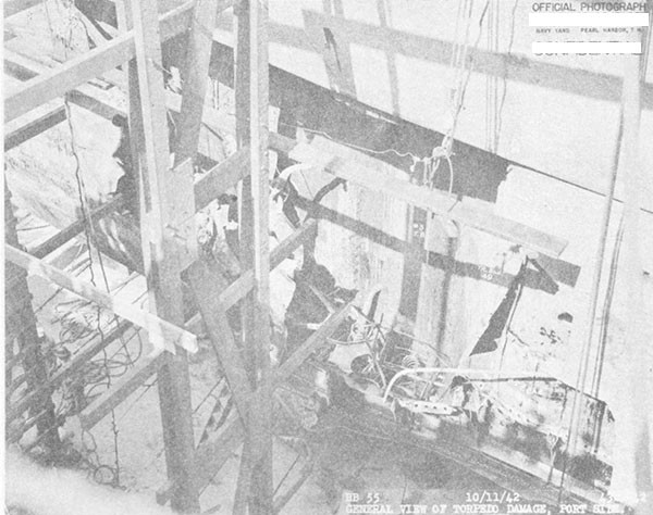
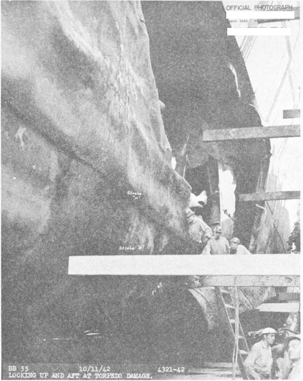
--40--
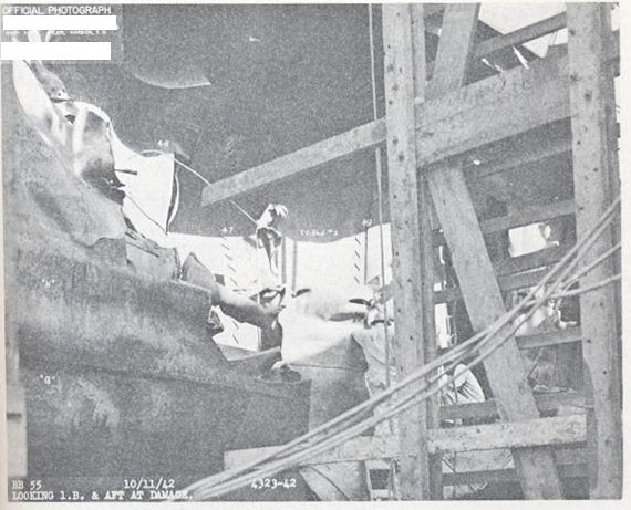
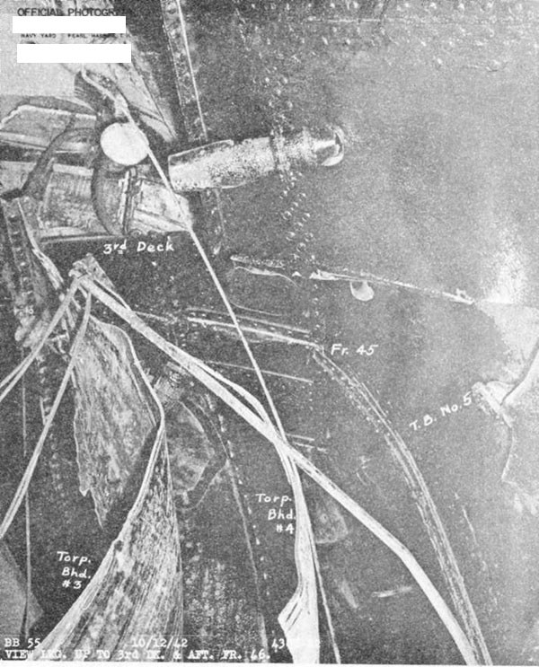
--41--
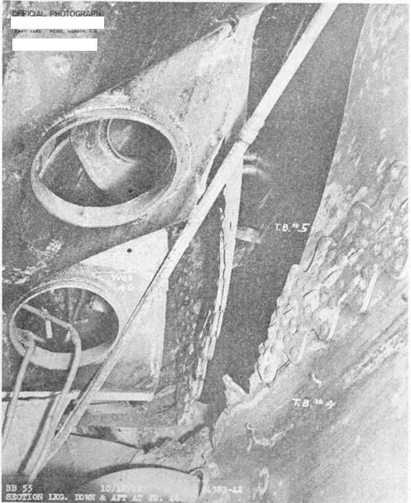
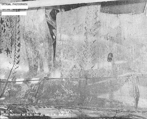
--42--
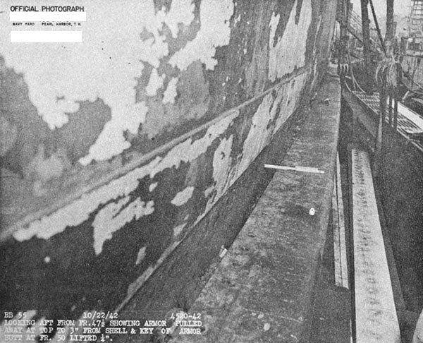
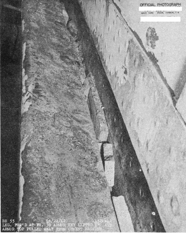
--43--
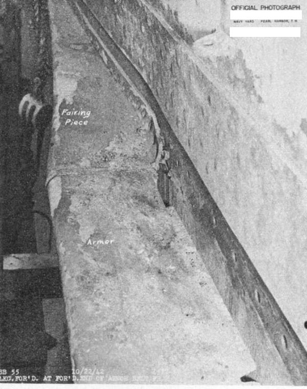
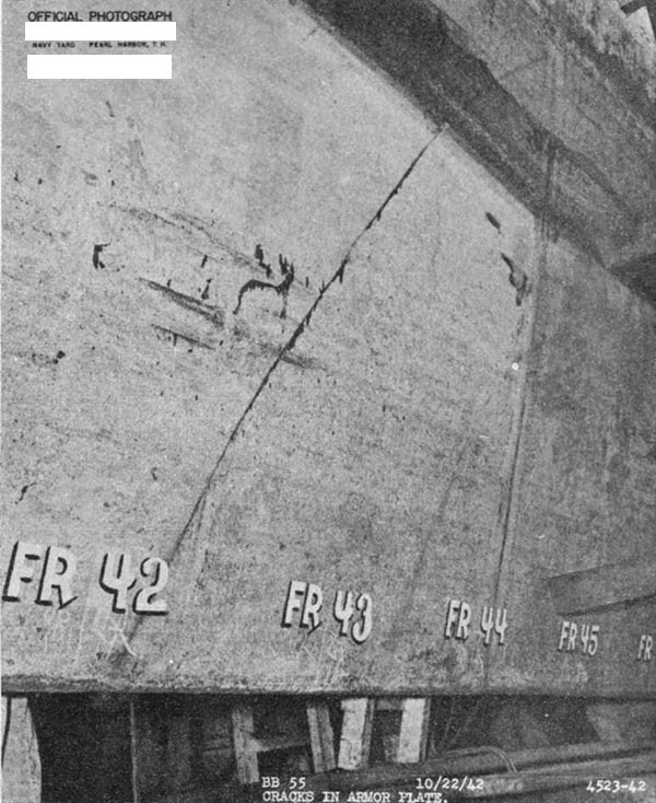
--44--
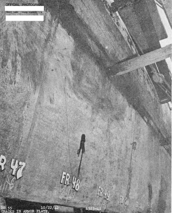
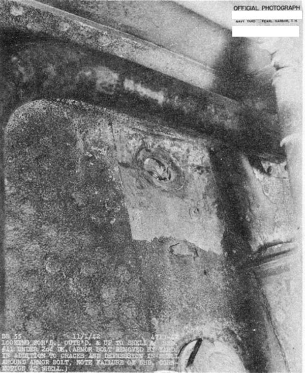
--45--
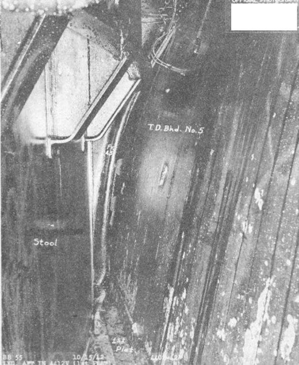
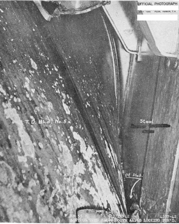
--46--
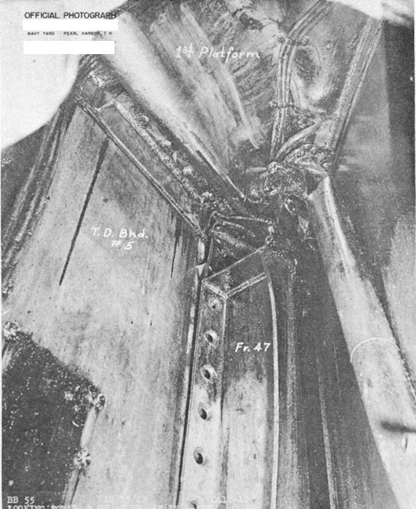
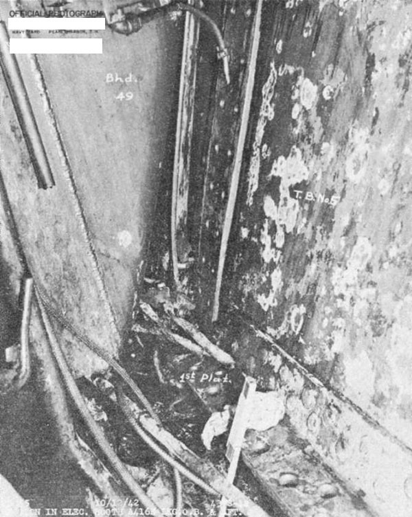
--47--
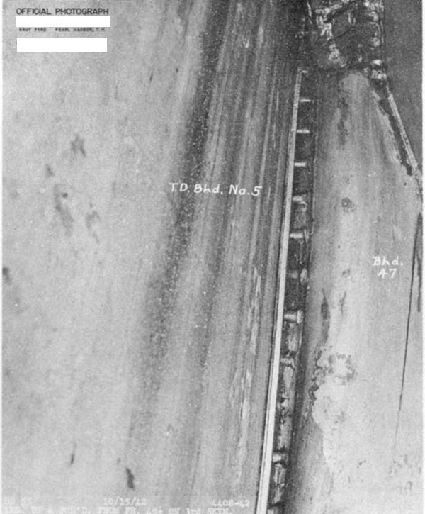
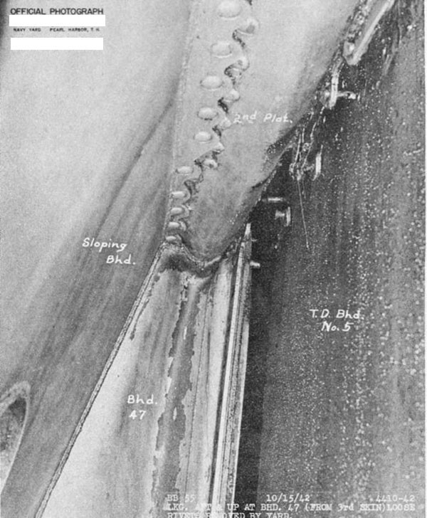
--48--
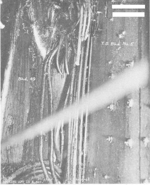
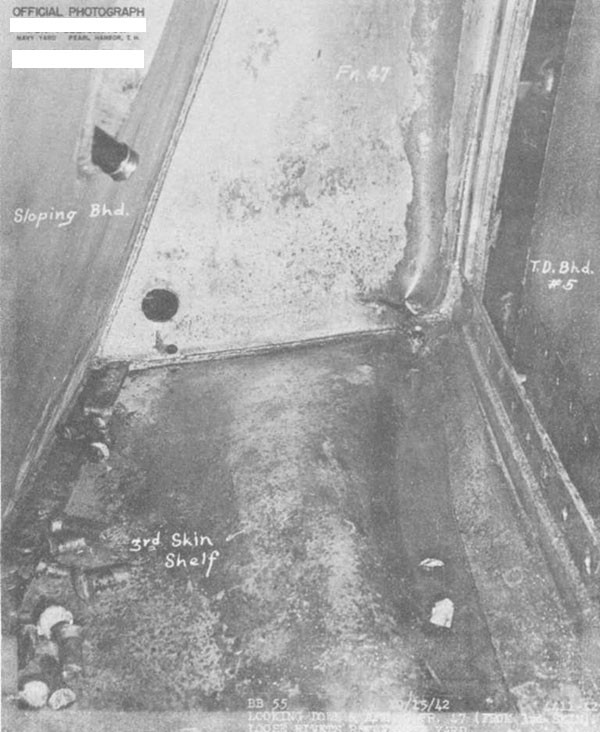
--49--
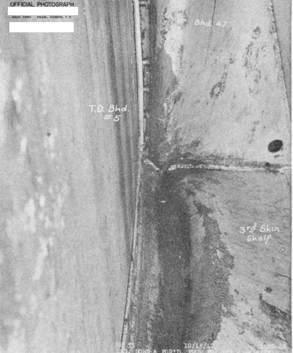
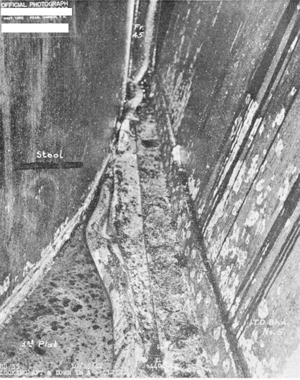
--50--
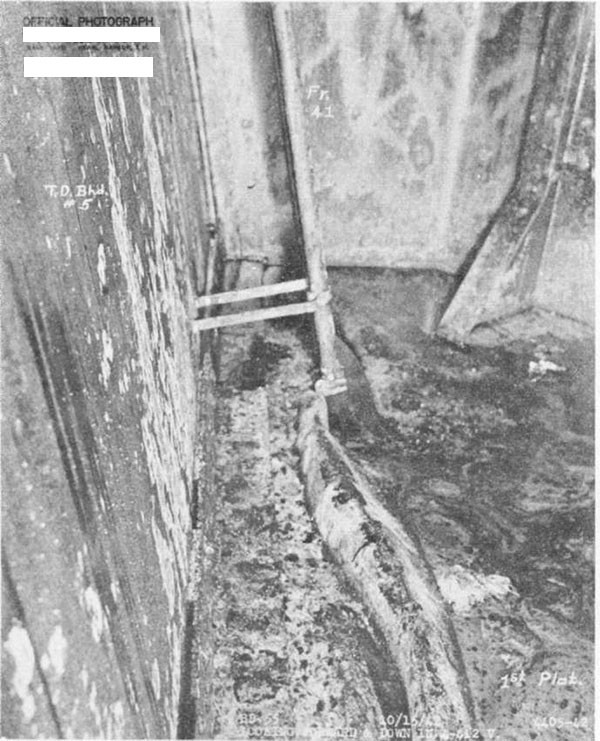
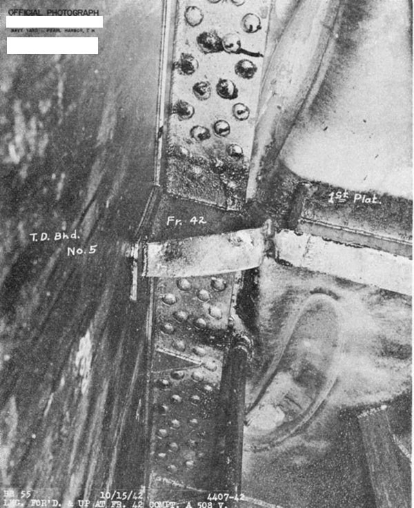
--51--
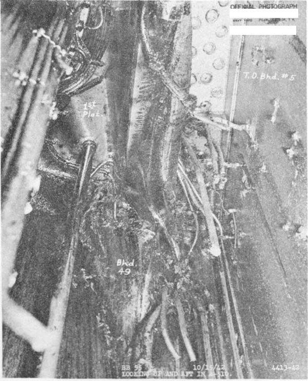
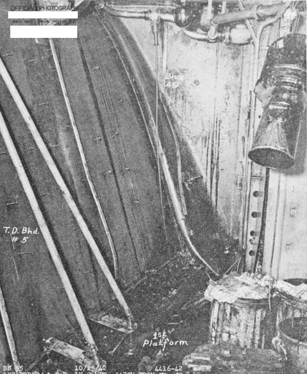
--52--
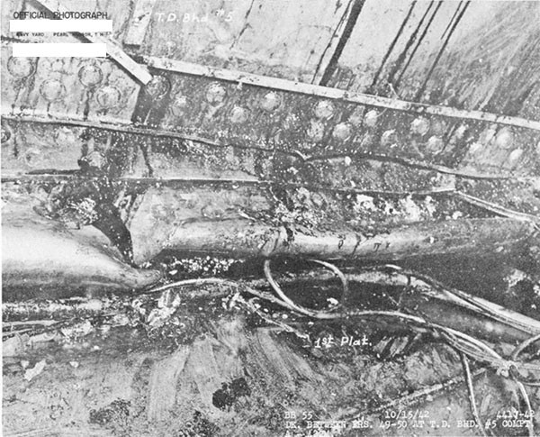
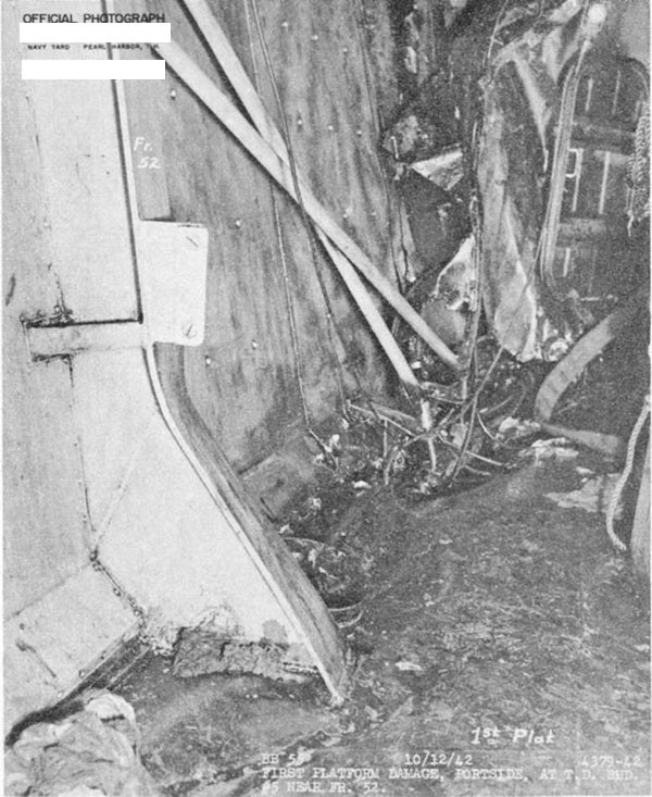
--53--
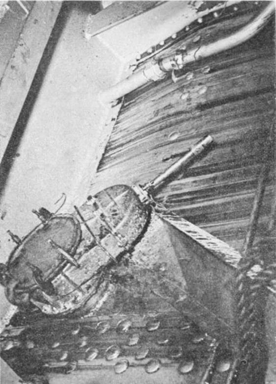
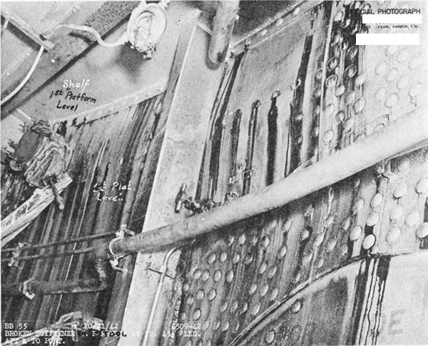
--54--
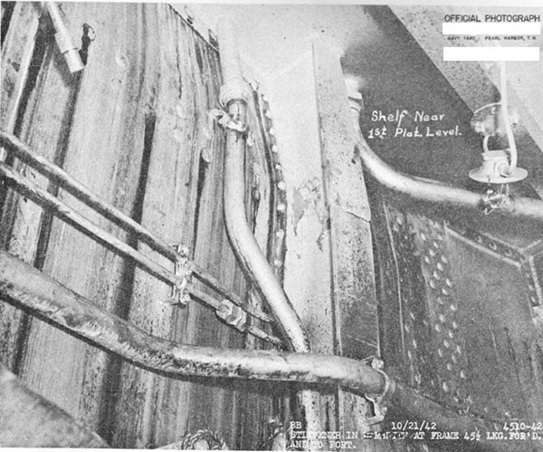
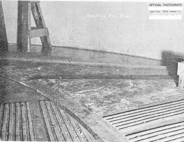
--55--
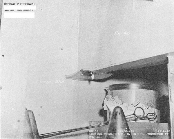
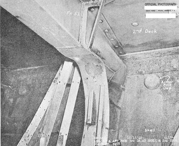
--56--
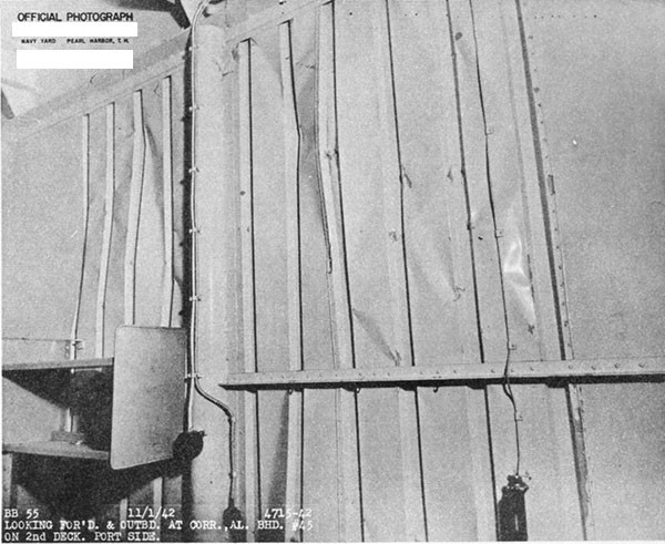

--57--
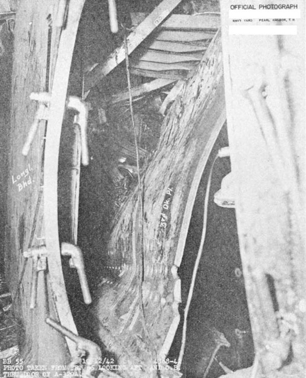
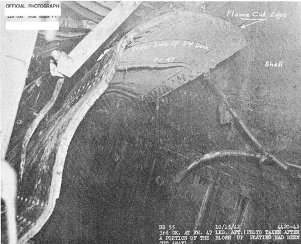
--58--
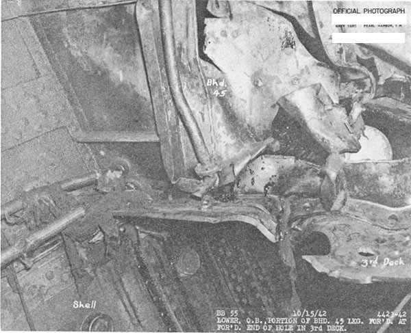
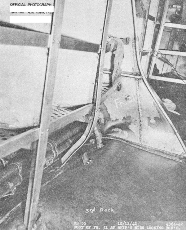
--59--
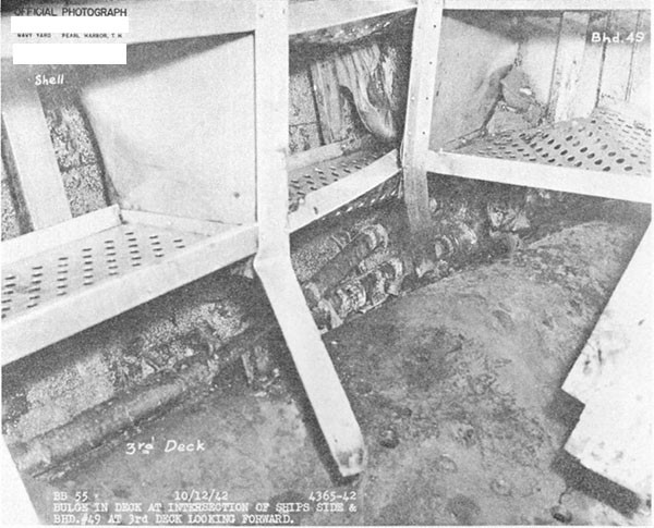
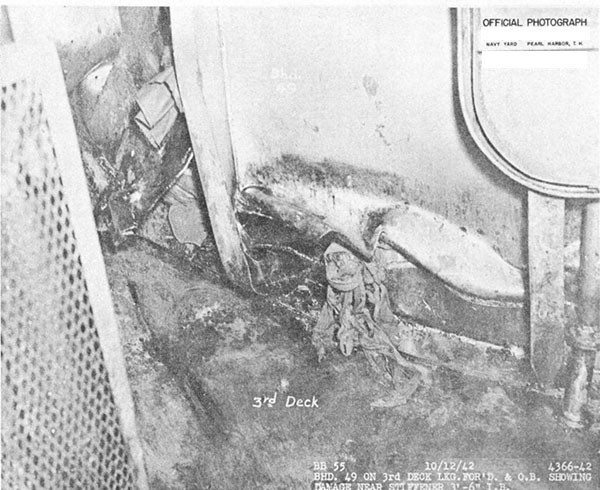
--60--
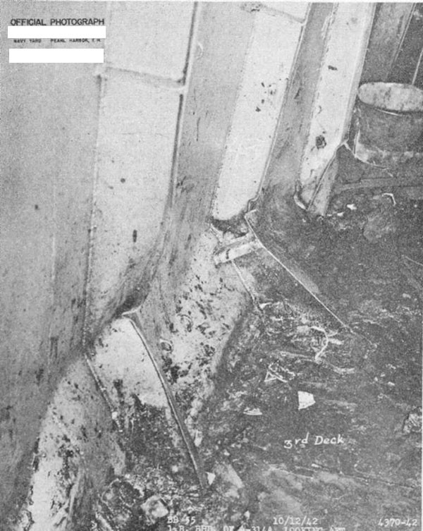
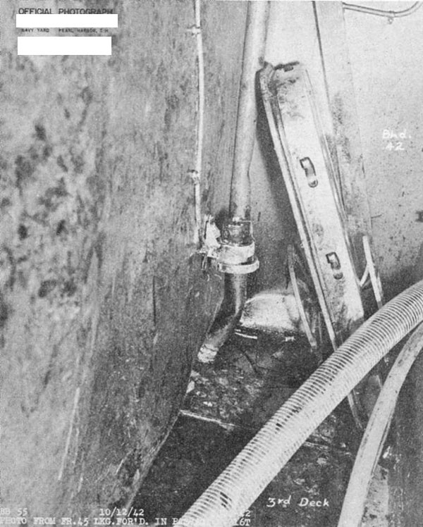
--61--
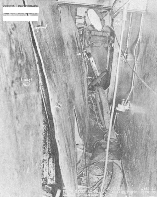
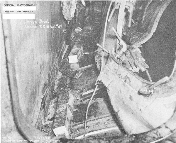
--62--
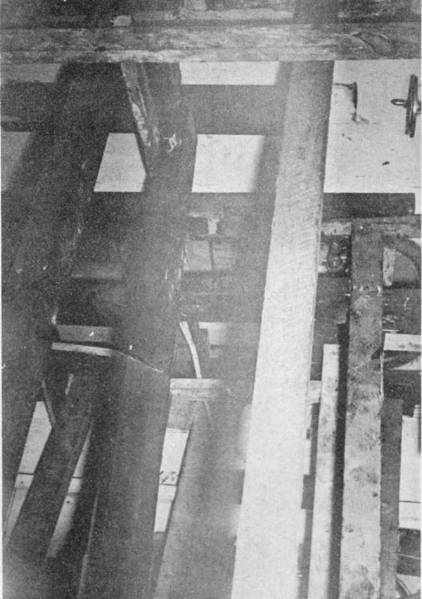
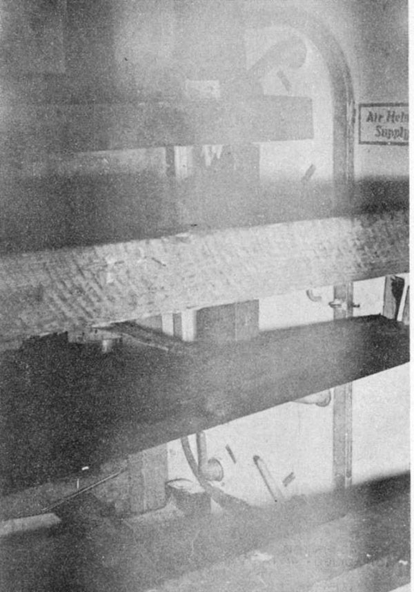
--63--
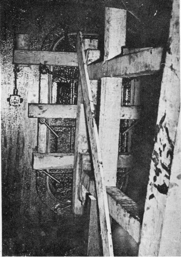
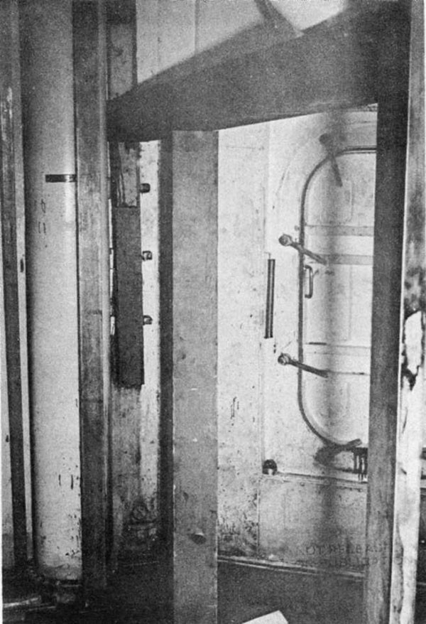
--64--
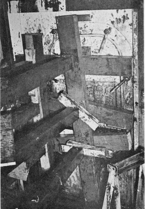
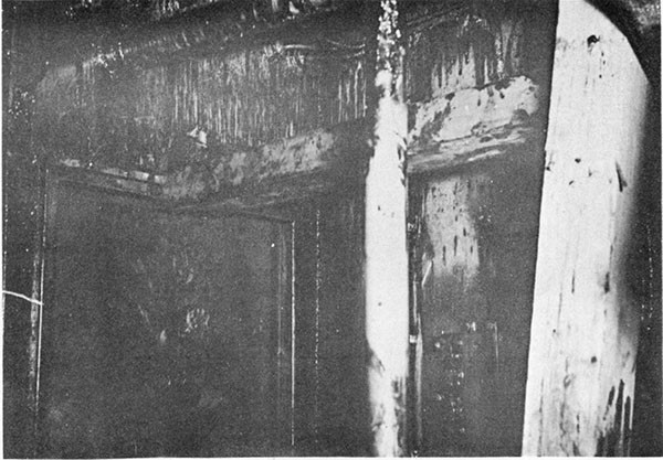
--65--
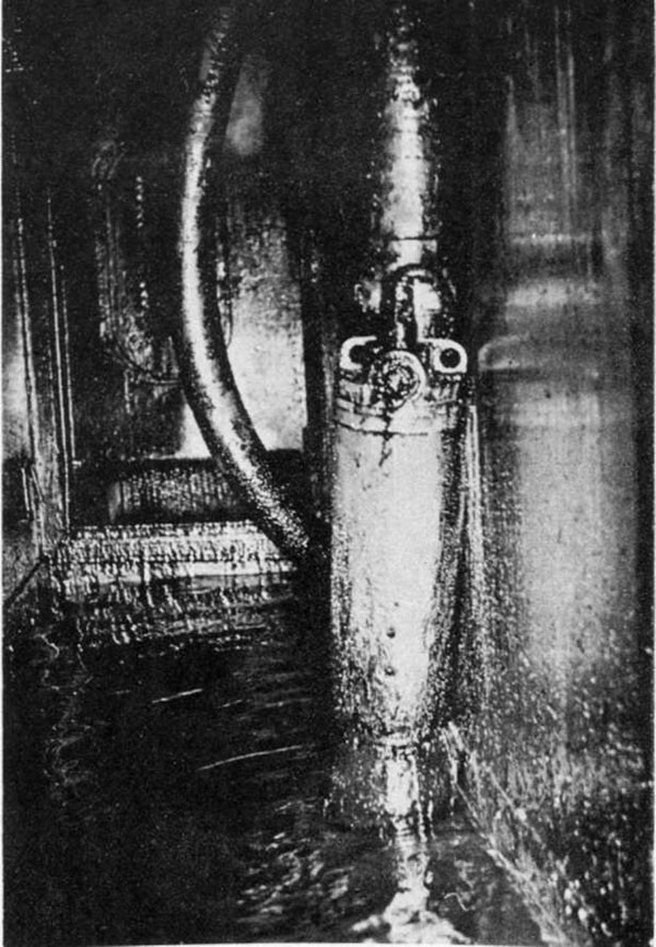
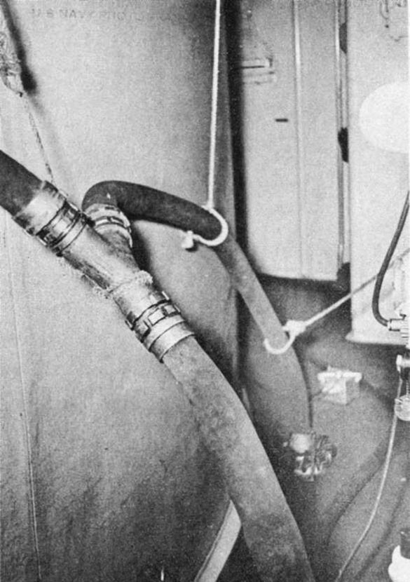
--66--
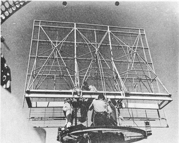
--67--
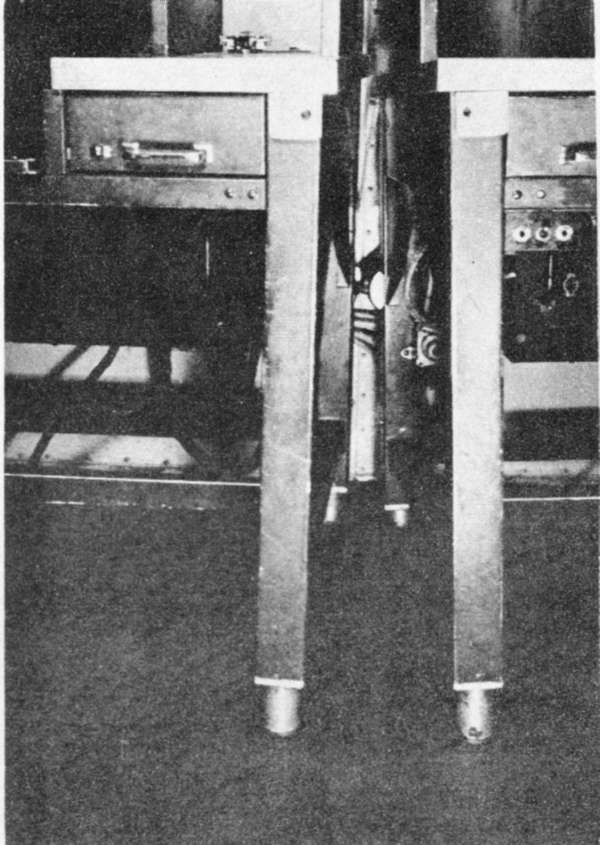
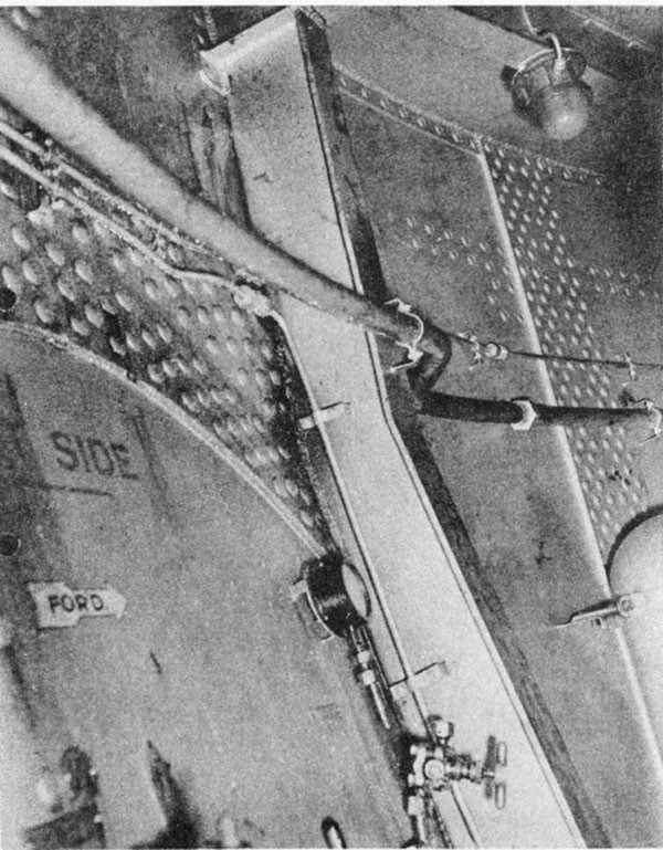
--68--
