
The Navy Department Library
U.S.S. Honolulu [CL48] Bomb Damage
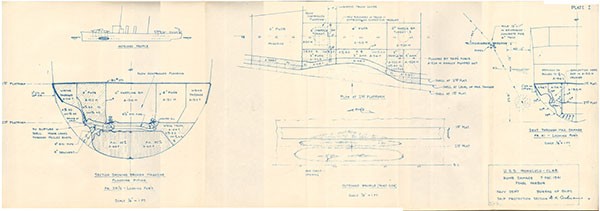
December 7, 1941. Pearl Harbor
![U.S.S. Honolulu [CL48] Bomb Damage cover image. U.S.S. Honolulu [CL48] Bomb Damage cover image.](/content/history/nhhc/research/library/online-reading-room/title-list-alphabetically/w/war-damage-reports/uss-honolulu-cl48-war-damage-report-no1/_jcr_content/body/image.img.jpg/1453404888133.jpg)
BOMB DAMAGE
DECEMBER 7, 1941.
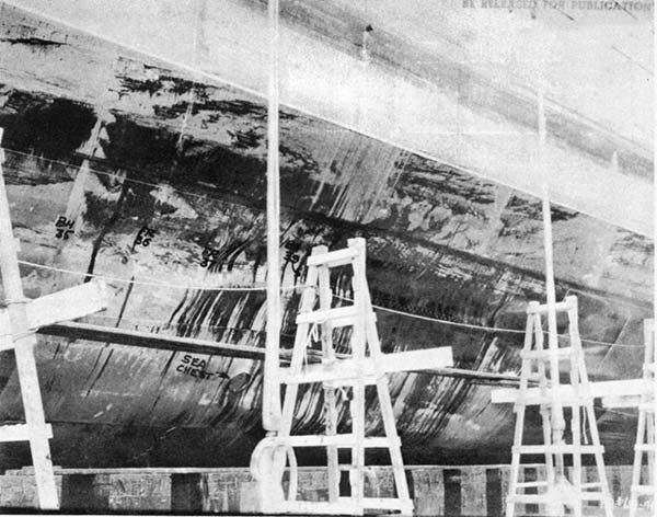
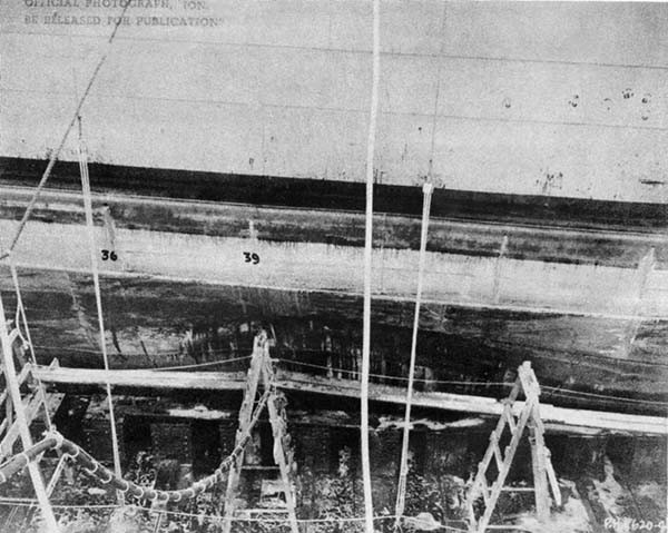
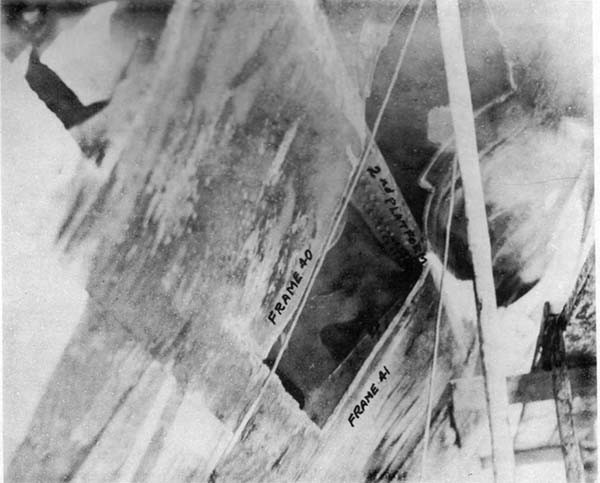
PEARL HARBOR
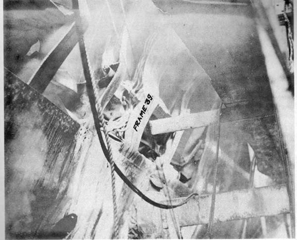
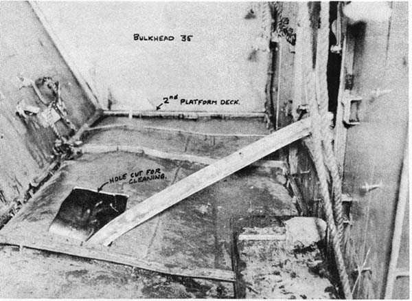
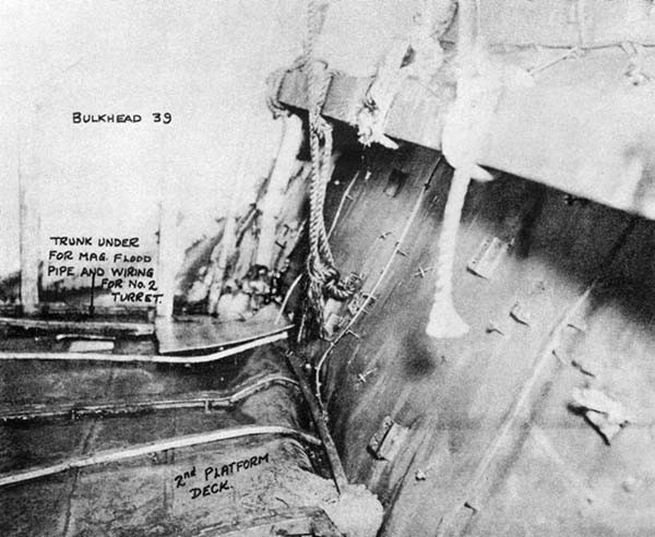
Bureau of Ships
Navy Department
Feb. 14, 1942.
U.S.S. HONOLULU
BOMB DAMAGE
Dec. 7, 1941
Pearl Harbor
| Class | 6" Cruiser (CL48) | Length | 600' |
| Date Launched. | August 1937 | Beam | 61' |
| Draft (before damage) | 23.9' | ||
| Displacement (Standard) | 10,000 tons | Draft (after damage). | 24.0' |
References:
(a) C.O. conf. ltr. to CinCpac, CL48/A16-3/(0279) of Dec. 11, 1941.
(b) Conf. despatch 200402 (Dec.) from Com 14 to Opnav.
(c) C.O. conf, ltr. CL48/S81/(01): War Damage Report, to BuShips, January 5, 1942.
(d) Pearl Harbor N.Y. Plan Sk-CL46-11/1-1.
Circumstances of the Attack
1. U.S.S. HONOLULU was moored port side to berth B-21, East Quay, Navy Yard, Pearl Harbor, on the morning of December 7, 1941. U.S.S. ST. LOUIS was alongside outboard. The depth of water here is 40 feet. The weather was clear, with scattered clouds. At 0755 Japanese planes were seen diving on Hickman Field and torpedo planes were observed approaching over Fleet Landing. General Quarters was sounded and the ship's antiaircraft batteries came into action.
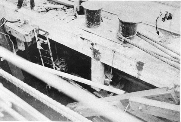
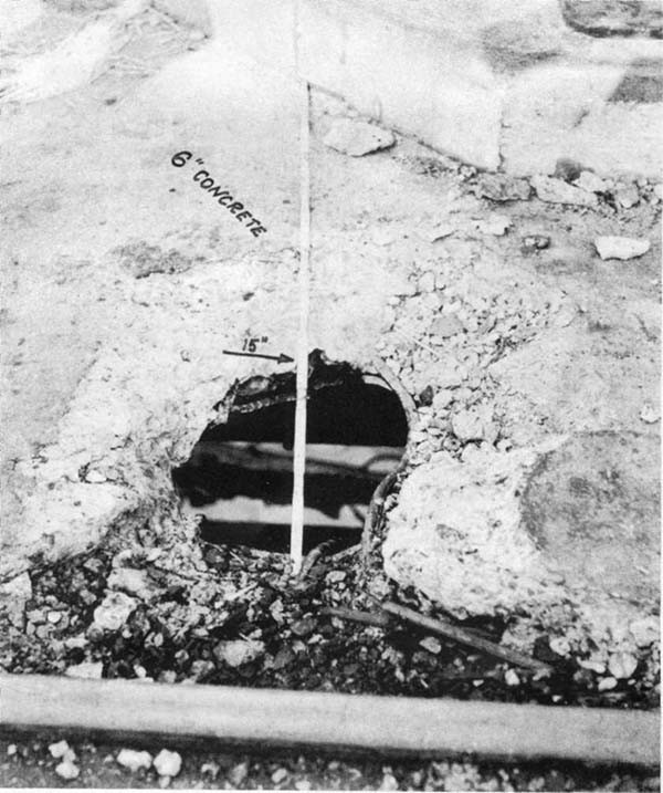
2. At about 0920 dive bombers attacked from the south to south east. One bomb, clearly visible on its descent, struck the pier about 20 feet from the ship's side at an angle of about 45 degrees to the vertical and almost at right angles to the edge of the pier. The dock edge was about 12 feet from the ship's side and about 12 feet above water. A hole approximately 17" x 15" was made in the six-inch reinforced concrete surface, and several large oil and water pipes under the dock were bent and ruptured; see Photos 1 and 2. The bomb exploded under
--1--
water at about frame 41, about level with the second platform deck. The probable position of the explosion is indicated on Plate I.
3. Little information is available on Japanese bombs. The 540-lb., 12-inch bomb containing 133 lbs. of TNT (particulars of dud found on airfield) might possibly have made the hole in the dock. But considering that the attack was on a ship, that the structural damage corresponded to a small charge, and that the hole in the concrete had a diameter of 15 inches, it is considered most probable that this was a 16-inch armor-piercing bomb carrying a relatively small charge for its weight. The explosion had a "muffled" sound. No flash or flame was noticed.
4. The ship was rocked by the explosion and whipped longitudinally, with the node of vibration apparently amidships and equal amplitudes fore and aft. No permanent set resulted from this bending.
5. The ship was in Material Condition Affirm, with all watertight doors and hatches closed.
Structural Damage
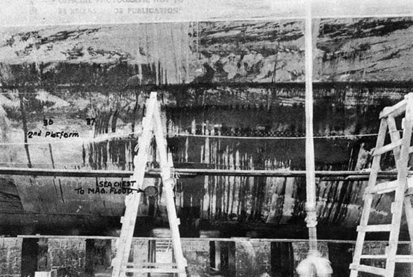
6. The indentation in the side extended from frame 34 to frame 47, and from Just above the first platform deck to within 6 feet of the keel - i.e., an area about 52' x 20'. The maximum of about 5 feet was at frame 41, between the first and second platform decks. The second platform deck acted as a stiffener with maximum indentations above and below it. This severe distortion of the shell caused no ruptures, and only minor leakage through pulled rivets. There was no penetration by fragments.
7. The longitudinal wiring passages A-514-T and A-516-T
--2--
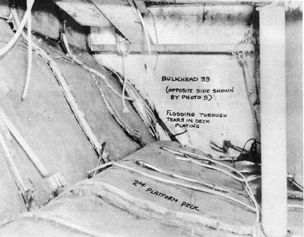
were crushed and flattened at the second platform level. The longitudinal bulkhead, which is the outboard bulkhead of powder magazines A-512-M and A-516-M, was forced in a maximum of about 3 feet. The deck in these magazines buckled sharply at the bulkhead and bulkheads 35, 39 and 45 were wrinkled; see Photos 8, 9 and 10. The deck in the central compartments A-515-M (6" powder) and A-510-M (No. 2 turret handling room) was slightly bulged.
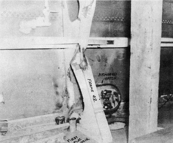
8. Above the first platform deck, bulkhead 39 was wrinkled for about 6 feet inboard of the shell. The 80-lb. STS deck bulged up about 4 inches over the stanchion in A-516-M, and web frame 42 was distorted as shown by Photo 11.
Shock Effects
9. The mercury was thrown from both the forward and after gyro compasses. The after main battery director range-finder was thrown out of adjustment (cement seal in ocular prism gave way). The forward director was also deranged optically, but was repaired immediately. The ball bearings of the oscillating nut of the elevating screw in Turret II were driven into the races about 0.004 inch.
Flooding
10. The fuel oil tanks in the double bottom in the forward part of the ship were full before damage. Flooding was principally, if not entirely, caused by fractures in the magazine flooding piping. This piping runs transversely in trunk A-614-T at frame 38-1/2, as shown on Plate I, to an 8-inch sea chest. The sudden thrust against the pipe at the sea chest caused two fractures at the risers leading up to the handling room A-510-M, and water was thus admitted directly to the trunk A-614-T.
--3--
11. Magazines A-512-M and A-616-M flooded immediately, the former probably through fractures in the after outboard corner (Photo 9) and the latter through breaks in the severely distorted second platform deck. The wiring passage abreast the explosion, A-516-T, flooded at once, but those forward and aft of it (A-514-T and A-518-T) flooded more slowly, taking at least an hour. Oil tank manholes in these passages were crushed and did not remain oil tight.
12. Magazine A-524-M and handling room A-522-M were flooded as a precautionary measure. The magazine was pumped out shortly thereafter, but the handling room was flooding from the damage. It was found that oil had risen to the tops of handling room A-522-M, magazines A-512-M, A-616-M, and wiring trunks A-614-T, A-514-T and A-518-T, showing that an oil tank had ruptured internally (probably A-612-F, at the transverse wiring trunk). There was slow oil leakage into wiring passage A-508-T through bulkhead 33.
13. Oil entered the handling room A-510-M through soft patches on the trunk A-614-T, directly underneath. Two submersible pumps were hooked up in series to pump this oil out over the main deck. This leakage slowed down after shoring and the pumps were secured.
14. Leakage from the wiring trunk A-614-T rose in the center column of Turret II about a foot above the deck in A-510-M, having probably come through cable stuffing tubes in the trunk bulkhead at frame 38, abreast the center column.
Damage Control Measures
15. Watertight doors to magazines were closed and shored after evacuation of personnel. A-522-M and A-524-M were
--4--
flooded as noted above. Magazine flood connections in non-damaged spaces on the same system were plugged. The deck and soft patches in A-510-M were shored. Armored hatches of A-514-T and A-518-T were shored down to make as oil-tight as possible. Slowly-flooding spaces were pumped out. List and trim were corrected by shifting fuel oil.
Electrical Damage
16. Flooding of the wiring passages described above completely grounded power leads to Turret II and partially grounded those to Turret I. This was probably caused, in the case of Turret II, by leakage through stuffing tubes in the wiring trunk into the junction boxes under the center column. It is also possible that sheaths of cables were ruptured in A-516-T and that leakage occurred through the interstices of the strands. All FC and IC circuits to Turret II were grounded. The ready light circuit in Turret III was grounded, due to the fact that the circuit is common to Turrets I and II also.
Ammunition
17. The ammunition in tanks in magazines A-512-M and A-516-M was flattened and crushed, but no primers were set off. It is possible that, had the ammunition cases been stowed athwartships instead of fore-and-aft, some primers would have exploded and caused serious fires and explosions. The hoist in A-522-M was inoperative.
Casualties
18. There were no casualties to personnel.
Recommendations and Conclusions
19. The following remarks are taken from reference (c), with the addition of Bureau comment.
--5--
(a) Magazine flooding piping should not be in wiring trunks. In this case a relatively minor damage immobilized one turret and possibly another because of grounds caused by the rupture of flood system piping. The Bureau is now taking steps to remove magazine flooding systems from ships. There have been none installed in new construction since 1937.
(b) Transverse wiring trunks should be subdivided so that the leads from port and starboard circuits will not both be Immersed in case one side of the trunk is flooded. In this case Turret II was completely without power from either side. The Bureau has now directed that centerline subdivisions be placed in such trunks, as indicated on Plate I, on all cruisers having this construction,
(c) Oil tank manholes in the decks of the outboard wiring passages should be moved inboard. This would give added security against flooding the passages with oil and would permit access to the tanks if the wiring passages are crushed. This recommendation is not considered of sufficient value to undertake changes in existing ships, and the arrangements in new cruiser designs differ so that the comment is inapplicable.
(d) Fore-and-aft ammunition stowage appears preferable to thwartship stowage; at least, in this case, no explosions resulted from crushed charges. (The ammunition referred to is the powder section of two-part charges; powder cases are of composition with primers in the base, and are stowed in individual tanks.)
--6--
(e) Insulation on magazine decks made it difficult to set shores. Insulation in magazines was also difficult to clear out after having been oil and water soaked. Insulation is required and no corrective measures are contemplated.
(f) Hatches in the armored first platform deck were reported as very difficult to tighten against the oil flooding the wiring passages beneath. The berthing spaces had some moderate flooding through these hatches. These hatches (see Photo 11) are flush, with dogs on the under side operated by a key inserted in a slot on the lug shank from above. The keys used have insufficient leverage for proper securing. It is difficult to get good leverage due to the proximity of the bulkhead. Dogs are not placed on top of armored hatches in order to avoid projections which might cause a shell to bite into the armor. This procedure, however, will be reviewed.
Effect on Fighting Efficiency
20. Fighting efficiency was seriously impaired. Turret II was out of action, and it is questionable whether Turret I could have gone into action. Both main battery directors were out of action, though one was quickly repaired.
--7--
[END]
