The Navy Department Library
U.S.S. Saratoga (CV3) Final Report
Torpedo Damage
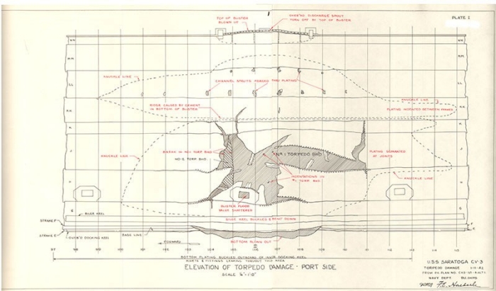
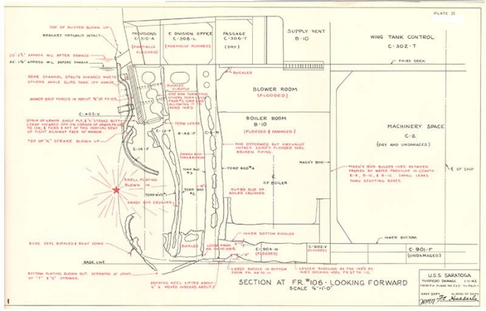
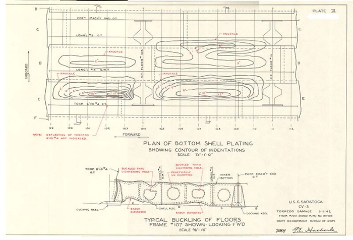
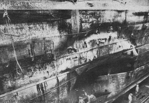
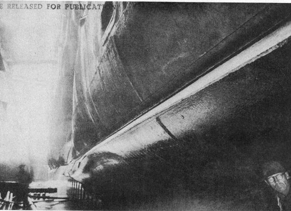
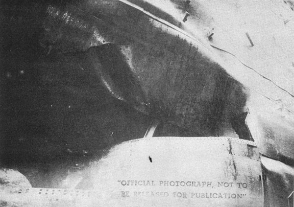
11 January 1942
CONFIDENTIAL
Final Report
U.S.S. Saratoga (CV3)
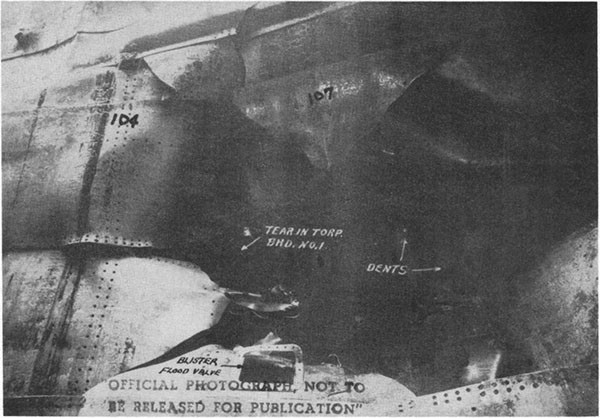
Torpedo Damage
11 January, 1942
The Chief of Naval Operations directs that this report be shown only to those persons to whom the report would be of value in the performance of their duties.
Steps shall be taken accordingly to insure that the report will be seen by those persons responsible for design, construction and repair of naval vessels, as well as for their operation, but by no others.
Preliminary Design Section
Bureau of Ships
Navy Department
15 November, 1942
WAR DAMAGE REPORT No. 19
Printed By U. S. Hydrographic Office
FINAL REPORT
U.S.S. SARATOGA
TORPEDO DAMAGE
January 11, 1942
| Section | Page | |
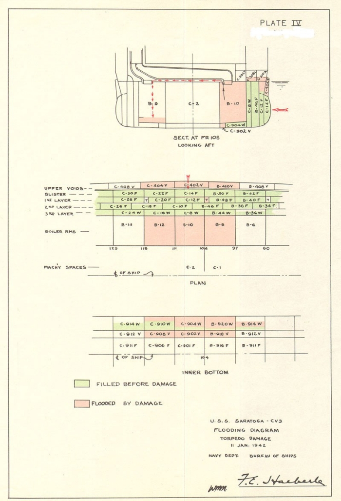
| I | Foreword | 1 |
| II | Structural Damage | 2 |
| III | Machinery Damage | 3 |
| IV | Electrical Damage | 3 |
| V | Piping Damage | 4 |
| VI | Shock Effects | 4 |
| VII | Flooding | 5 |
| VIII | Counter Flooding & Transfer of Liquids | 6 |
| IX | Remark on Torpedo Protection | 6 |
List of Photos
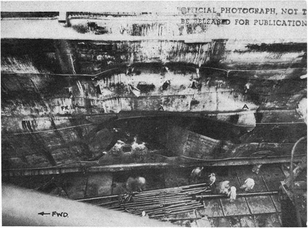
| Photo 1: View from side of dock. Ridge A-A is at the junction of the upper and lower blisters where the inaccessible outboard corner is filled with cement. | 9 |
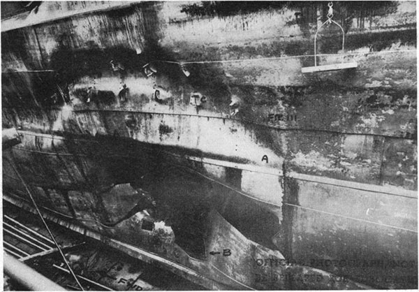
| Photo 2: View from half-way down the dock, looking forward. Countersunk rivets pulled out at B. Channel struts in upper blister pierced the plating as at C. | 9 |
| Photo 3: View from half-way down the dock looking aft. | 10 |
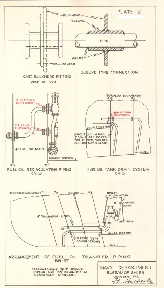
| Photo 4: View from directly opposite the damage showing torpedo bulkhead No. 1 and the forward edge of the hole. | 10 |
| Photo 5: After edge of the hole. | 11 |
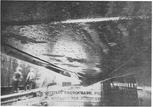
| Photo 6: View looking forward along the port bilge keel. Note how the bottom plating inboard of the bilge keel was blown down by the explosion. | 11 |
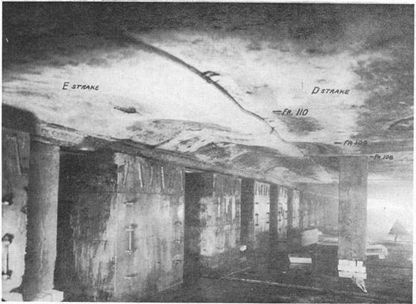
| Photo 7: View forward along the outer row of keel blocks. Note that the docking keel is bowed up (D). The maximum lift is about 6 inches. | 12 |
| Photo 8: View inboard of the outboard docking keel looking forward and showing shell indentations. (See plate III). | 12 |
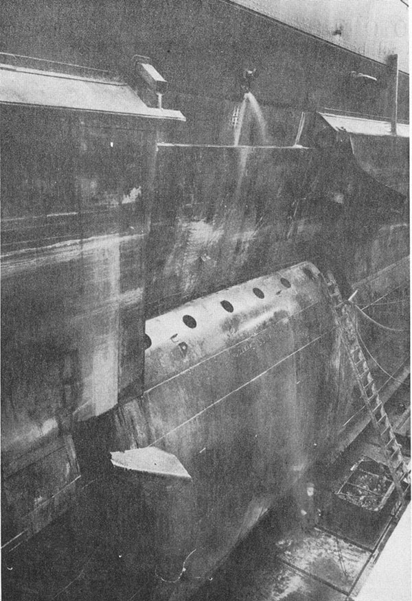
| Photo 9: General view of temporary patch on arrival at Puget Sound looking aft and showing plating peeled back by action of the sea. | 13 |
List of Plates
| I | Elevation of Damage. |
| II | Section of Damage at Frame 106. |
| III | Contour of Indentations on Bottom. |
| IV | Flooding Diagram. |
| V | Piping. |
| Class | Aircraft Carrier (CV3) | Length | 850' |
| Launched | April 1925 | Beam | 105'6" |
| Displacement (standard) | 33,000 tons | Draft before damage | 32'1" |
| Draft after damage | 33'2" |
References:
(a) Navy Yard P.H. conf. despatch 180500 (January) to Buships.
(b) Combatfor conf. despatch 200400 (January) to Buships.
(c) Comdt. P.H. ltr. C-L11-l/CV3/NY10(Y0129) to Buships, January 23, 1942.
(d) Navy Yard P.H. conf. despatch 280510 (January) to Buships.
(e) C.O. SARATOGA ltr. CV3/Al6-3/L11-l/(50-hl)(011) to Buships: War Damage Report, February 6, 1942.
(f) Cincpac ltr. L11-l(l)/50 Serial 0355 to Buships, forwarding C.O. SARATOGA report of liquid loading, February 2, 1942.
(g) Comdt. P.H. ltr. C-L11-l/CV3/NY10(Y-0390) to Buships, March 2, 1942, War Damage Report.
(h) Comdt. Puget Sound ltr. CV3/L11-l(M-3A) to Buships, March 18, 1942, War Damage Report.
(i) C.O. SARATOGA ltr. CV3/L11-l(70-rfc)(030) to Buships, March 28, 1942, War Damage Report, Additional Information.
(j) Comdt. Puget Sound ltr. CV3/L11-l(M-3A) to Buships, April 14, 1942, Final Report on War Damage.
Section I - Foreword
1. Bureau of Ships Report of Torpedo Damage to USS SARATOGA, dated 14 February, 1942, was a preliminary report of this damage based on information available at that time. For completeness, most of the information contained in that report is repeated or revised in this report, which also includes some later information.
2. SARATOGA was making 15 knots in the early evening of January 11, 1942, when struck by one torpedo on the port side in way of Boiler Room B-10. Boiler Rooms B-8, B-10, and B-12
--1--
were flooded principally through fractured piping. Speed was increased to 17 knots. List was corrected both by counter-flooding and transferring oil and water from port to starboard until a slight starboard list resulted.
Section II - Structural Damage
3. Structural damage is shown by Plates I, II and III and the photographs. A large area of plating was dished in (Photos 1 and 2) and a jagged hole about 30 feet long was torn in the shell plating between frames 104 and 111. It extended vertically from the bottom of the armor belt downward about 20 feet. The bilge keel buckled and bent down, but remained practically in its original position, and a hole was blown out of the bottom between the bilge keel and the outboard docking keel. This hole was about 24 feet long and was made by opening the seam between H and G strakes as shown in Plates I and II. The outer docking keel was bent up about 6 inches and inboard about 3 inches in way of the explosion and the bottom plating and floors buckled and distorted as far inboard as longitudinal No. 3 (Plate III).
4. There was a well defined ridge along the center of the dished in area and just above the hole in the shell. This was produced by the cement which had been used to fill the lower corner of the blister. The plating above this ridge was blown in and against the armor and the transverse braces were forced through the plates as shown in Plate II and Photos 1, 2 and 3. The top of the blister was blown upward.
5. The ripping of riveted seams and butts is quite noticeable in the photographs. Points of countersunk rivets appeared to pull out readily, leaving the rivets still sticking in the other plate as seen in the seam marked B in Photos 2 and 3.
6. The armor belt is made up of twelve-foot plates of Class A armor tapered from 7 inches at the top to 5 inches at the bottom and with keyed butts at frames 102, 105, 108, and 111. At Frame 102 there was no displacement, but at frame 105 the belt was forced inboard about 1/2 inch, and at frame 108 it was forced inboard about one inch. There was no distortion of these two plates. The next plate aft (frames 108-111) had its after end pushed outboard approximately one inch. This plate was found to be dished in about 1-1/4 inches at mid-length. The displacement of the plates may have been due to the explosion and it is possible that the one dished plate was damaged by the explosion. This seems improbable, however, in view of the fact that adjacent plates, which were nearer the explosion, were not distorted. Curvature tolerances for class A armor allow one inch and class A armor is prone to change its shape with age. It thus seems more probable that this plate was curved before the explosion.
7. Torpedo bulkhead No. 1 was torn loose at its top and bottom connections and blown in a maximum of about 5 feet, crushing the intervening swash plates to within about a foot of bulkhead No. 2. A hole about 10 feet by 3 feet was torn in it as indicated on Plate II. This is just visible on the left in Photo 4. Also visible are several indentations in the bulkhead.
--2--
These were probably caused by fragments of the torpedo or the blister flood valve which was almost at the point of explosion and which was completely shattered (Plate II).
8. Torpedo bulkhead No. 2 held at the third deck but pulled loose at the bottom and deflected inward about 3 feet. The armor backing webs which are attached to the top part of this bulkhead were opened out by its deflection. They failed through the lightening holes as shown on Plate II.
9. Bulkheads 3 and 4 appear to have held very well. No. 3 pulled loose for a few feet at the bottom and bulged inward about 18 inches. No. 4 remained structurally tight except for a few rivets at the bottom. It deflected inboard about 12 inches where it was hard up against the foundations of No. 10 boiler. Bulkheads 2, 3 and 4 all deflected in long, easy sweeps.
10. Transverse bulkheads bounding No. 10 boiler room were deeply wrinkled for about 8 feet inboard of No. 4 torpedo bulkhead. The escape trunks from boiler rooms 8 and 10, which were in the outboard corners of bulkhead 104, were crushed and distorted.
11. Temporary repairs were made at Pearl Harbor. Torpedo bulkheads 3 and 4 in way of the explosion were repaired permanently and welded to damaged plating at the bottom. These were made as tight as possible in the time allowed. A free flooding patch was then installed outboard in way of the damage and faired into the existing structure. In passage to the Navy Yard, Bremerton, for final repairs this fairing was pulled off by the sea as shown in Photo 9.
Section III - Machinery Damage
12. Boilers 8 and 10 were damaged by the explosion. The front plate and casing of No. 8 were damaged by shearing bolts and rivets and the brick pans were damaged, but the tubes and drums were reported in good condition.
13. Boiler No. 10 was quite extensively damaged. It was pushed from its foundation, the port water drum was damaged and both boiler and superheater tubes were distorted. The water side of the boiler flooded with oil and it was necessary to boil it out. This boiler was steaming when damaged, Nos. 8 and 12 were not.
14. Boiler No. 12 was not damaged by the explosion, but all three boilers were flooded with water and oil and this soaked all the brickwork and insulation sufficiently to require renewal.
15. No. 10 fuel oil heater and the foamite fire extinguishers in both No. 8 and No. 10 firerooms were wrecked. All piping in wing tanks was damaged beyond repair and much of the piping in B8 and B10 was damaged, particularly lines near the outboard bulkhead.
Section IV - Electrical Damage
16. Electrical damage resulted primarily from the flooding of the firerooms and consequent saturation and shorting of cables
--3--
with water and oil. Apparently some panels mounted on the outboard machinery space bulkhead were soaked by minor leakage through this bulkhead (reference (g)), and some cables fed water and oil to junction boxes in the undamaged compartments. This is to be expected where water can get into cables and has caused trouble in other cases of damage, a good example of which is the experience of HELENA (Bureau of Ships War Damage Report No. 4, dated February 21, 1942).
17. The auxiliary lighting circuit on SARATOGA was arranged with all the firerooms on one side on the same circuit and consequently the flooding of one fireroom shorted out the others. It was recommended and approved that this system be modified to segregate the lighting in firerooms and machinery spaces. This situation was investigated and corrected on all carriers and steps are being taken to cover other combatant types.
Section V - Piping Damage
18. Piping and operating gear were destroyed, displaced or jammed extensively. Items listed in references (g) and (i) include piping to tanks outboard of all three firerooms which ruptured at the holding bulkhead. Most of these lines broke at the flanges of the cast steel bulkhead spools, but did not open up completely. These broken fittings were the chief source of flooding in these firerooms. Piping in B10, adjacent to the explosion, particularly that running along the outboard bulkhead, was extensively damaged.
19. Reference (g) listed remote control rods and bevel gears for valves to tanks outboard of both B8 and B10 as having been damaged beyond repair. This equipment is comparatively easy to put out of action and two means of avoiding this trouble are being used on new construction:
(1) A hydraulic system of controlling valves in which the valves are operated by hydraulic motors piped to a remote hydraulic driving unit. The piping is protected as well as possible and will allow some distortion without failing.
(2) Flexible cables which take the place of rods and gears and will allow considerable distortion of bulkheads and decks without jamming.
20. The foamite air supply line was damaged in B8 and B10 and the lead lining was ruptured in two tanks.
Section VI - Shock Effects
21. Shock to the ship did not cause widespread damage. Piping and fittings in the boiler rooms were fractured, though how much of this damage was due to the distortion of bulkheads and how much to shock is not clear. Items of damage definitely attributable to the shock were:
(1) In the engine room abreast the explosion, the main throttle tripped (but was reset at once).
--4--
(2) The condenser head was cracked.
(3) The 750-KW generator brush rigging carried away.
(4) Gauge board in engine room damaged (no details).
(5) A number of circuits, including I.C., engine order telegraph, telephones, call bells, general alarm and lighting circuits were shorted (cause not stated).
(6) Circuit breaker opened in lead to shell hoist in No. 2 turret.
(7) Cast aluminum pedestal ring for forward FC Radar cracked beyond repair.
Section VII - Flooding
22. Plate IV shows the condition of loading before damage and the flooding due to damage. All the layers of the torpedo protection system in way of the explosion were full except the tank between torpedo bulkheads 1 and 2 (C12F) which was about 70% full. The upper void compartments outboard of the armor were empty, and there was not much liquid in the port double bottom tanks in way of the damage.
23. As stated in paragraph 10 the inner bulkheads of the torpedo protection held and remained reasonably tight. If there had been no other considerations nothing inboard of this bulkhead would have been flooded. Actually, however, the fittings at the bulkhead failed as discussed in paragraph 19, and in B8 and B10 the piping within the firerooms also ruptured. Within 10 minutes B10 was full and by 1950 (35 minutes after the hit) B8 and B12 were full.
24. The third deck was pulled down by the distortion of the torpedo bulkheads and this caused sufficient leakage to fill third deck provision compartments C310A and B332A and the 'E' division office, C-308-L, to the waterline.
25. Some flooding took place in the corresponding starboard firerooms to a depth of about two feet above the inner bottom. This occurred through air holes and joints in the uptake, the water going across the third deck and down through the starboard uptake as shown on Plate IV. If the draft had been slightly greater the three starboard boiler rooms, corresponding to those flooded to port, might have been completely flooded.
26. An alteration subsequently directed by the Bureau of Ships removed this danger of cross flooding through uptakes. The port and starboard uptakes are made entirely separate to the hangar deck, and a watertight fore and aft bulkhead is placed between them, following their curvature in the transverse plane. This prevents water from crossing the third deck whether uptakes are watertight or not.
--5--
Section VIII - Counterflooding and Transfer of Liquid
27. The five following compartments in the starboard torpedo protection layers were counterflooded:
B-31-F B-47-F
B-39-F B-49-F
B-41-F
Oil was transferred from port tanks
C-36-F D-12-F
B-38-F D-16-F
C-48-F D-20-F
D-10-F D-24-F
to starboard tanks
B-21-F C-13-F
B-2J-F C-21-F
B-29-F B-47-F
These moves are best visualized by reference to the flooding effect diagram in the ship's Damage Control Book.
28. About 1100 tons of water entered the ship from the damage, and about 320 tons were admitted by counterflooding. Transfer of oil from port to starboard was continued until the port list was removed and the list to starboard was about 1-1/2 degrees. The counterflooded tanks were then pumped out and a slight list to starboard was maintained.
Section IX - Remarks on Torpedo Protection
29. It has been said in despatches that this incident indicates that Japanese torpedoes are unusually destructive, and a charge of from 750 to 1000 lbs. is estimated by reference (e). Very little information is available on Japanese submarine torpedoes. The Bureau, however, does not agree that this damage was exceptionally severe. It was little if any more than might be expected from one of our submarine torpedoes carrying 500 lbs. of explosive.
30. All layers in the torpedo protection system were filled with liquid, whereas at least one void layer is essential for good protection. In particular, the innermost full tank permitted the transmission of shock directly to the boiler room bulkhead. Had this space been void (a primary objective in all such systems) it is possible that the boiler rooms would not have flooded. It should be noted, however, that in this ship there are lightened floors between torpedo bulkheads Nos. 3 and 4. These failed by buckling and tearing between lightening holes, and the distorted floors would have transmitted a good deal of the force of the explosion from torpedo bulkhead No. 3 to torpedo bulkhead No. 4, even though the space between these bulkheads had contained no liquid.
31. It appears that the shell and the first two bulkheads were holed by the explosion; the third was torn loose at the
--6--
bottom, and the fourth was virtually intact. Experience, both from war damage studies and from experiments, is that no better resistance can be expected. From several viewpoints the torpedo protection served better than would have been predicted. It is consequently believed that the torpedo carried not more than a 500-lb, charge, possibly less.
32. Recent experiments have shown that the extent of damage to the shell plating is reduced by carrying the outboard tanks full and as discussed above. The innermost bulkhead in a torpedo protection system has the best chance of holding if tanks immediately outboard of it are empty. Moreover, carrying one or two layers of liquid outboard has a very important effect in reducing the angle of heel after damage because:
(1) The fore and aft extent of damage to a void layer is apt to be less if the void layer is inboard rather than outboard. Less water is, therefore, admitted to the ship.
(2) The heeling moment produced by water admitted in damage will be less when an inner void is flooded rather than an outer void because its distance from the centerline of the ship is less.
NOTE: These principles are set forth in FTP 170-A, 1942 "Damage Control and Chemical Warfare Instructions"
33. The loading conditions of SARATOGA and LEXINGTON left much to be desired, however, due to the necessity for balancing the island with liquids on the port side. This condition could be remedied and fuel capacity maintained only by installation of a blister on the starboard side. This blister was proposed some years ago but was not installed at that time. The damage to SARATOGA emphasized the importance of the question and at the same time provided an opportunity to install the blister without undue extension of the repair period. Major changes were also made in the battery of SARATOGA which materially reduced the weights and unbalance to starboard.
34. The alterations to SARATOGA made during her repair period give the following advantages:
(a) Increased buoyancy and stability. These are provided by the blister. A further increase in stability resulted from reduction of topside weights.
(b) Greater total amount of fuel carried without list. This follows from the reduction of starboard weight and the increase of starboard buoyancy.
(c) Best liquid distribution for resisting underwater damage and minimizing heel after damage. Two complete layers of liquid may be carried outboard next to the shell in way of boiler rooms, with the inner row of tanks empty.
(d) Improved torpedo resistance on starboard side. The blister adds another protective layer.
--7--
35. The outstanding weak spot in the torpedo protection of SARATOGA was the piping at the inner torpedo bulkhead. All three firerooms flooded principally because of failure of this piping as discussed in paragraphs 19 and 20. Plate V shows some of the typical sources of trouble on SARATOGA and also shows the fuel oil transfer piping arrangement on BB57. Present piping installation is kept as near to the bottom of the holding bulkhead as possible, and where it must run fore and aft or vertically it is desirable to keep it at least 15 inches inboard of this bulkhead. Where possible piping is run through the holding bulkhead below the inner bottom and then up as illustrated for BB57, Plate V.
36. In addition to these improved arrangement practices the type of bulkhead fitting used is superior to the older type which failed on SARATOGA. As sketched on Plate V the piping is welded to a sleeve which is welded to the bulkhead. This does not involve cutting a large hole in the bulkhead to pass spool flanges nor does it have the stiffness that a heavy spool fitting has. Its only disadvantage is that it is a permanent installation and must be cut out if removal is desired. It may be noted on Plate V, moreover, that the welded fitting for the 2-inch fuel oil tank drain system on CV3 held while the adjacent cast fitting failed.
37. U.S.S. LEXINGTON, when torpedoed in way of firerooms 2, 4 and 6 apparently experienced the same type of failures although not to the same degree as SARATOGA. LEXINGTON was able to pump these firerooms dry and could have placed them in operation if needed. However, the fact that cast spools in the holding bulkhead are a source of weakness is readily apparent.
--8--
--9--
--10--
--11--
--12--
--13--
