The Navy Department Library
Submarine Report
Depth Charge, Bomb, Mine, Torpedo and Gunfire Damage Including Losses in Action
7 December, 1941 to 15 August, 1945
Volume 1
CONFIDENTIAL
Submarine Report
Depth Charge, Bomb, Mine, Torpedo
and Gunfire Damage
Including Losses in action
7 December 1941 to 15 August 1945
Volume 1
The Chief of Naval Operations directs that this report be shown only to those persons to whom the report would be of value in the performance of their duties.
Steps shall be taken accordingly to insure that the report will be seen by those persons responsible for design, construction and repair of naval vessels, as well as for their operation, but by no others.
Preliminary Design Section
Bureau of Ships
Navy Department
1 January 1949
WAR DAMAGE REPORT No. 58
Printed By U. S. Hydrographic Office
SUBMARINE REPORT
Depth Charge, Bomb, Mine, Torpedo and
Gunfire Damage
Including Losses in Action
7 December, 1941 TO 15 August, 1945
1 January 1949
APPROVED

C. L. BRAND
Rear Admiral, USN
Ass't. Chief of Bureau for Ships
| Page | ||||||
| I | FOREWORD | 1 |
||||
| II | GENERAL | 2 |
||||
| III | JAPANESE ANTI-SUBMARINE WARFARE AND WEAPONS | 8 |
||||
| Name | No. | Damaged by | Locale | Date | ||
| IV | PERCH | 176 | Depth Charge | Java Sea | 3/3/42 | 17 |
| V | KINGFISH | 234 | Depth Charge | Formosa | 3/23/43 | 26 |
| VI | TUNNY | 282 | Depth Charge | Palau Is. | 8/26/43 | 47 |
| VII | SALMON | 182 | Depth Charge | S.E. of Kyushu | 10/30/44 | 61 |
| VIII | GRENADIER | 210 | Bomb | Malaya | 4/22/43 | 82 |
| IX | SCAMP | 277 | Bomb | Mindanao, P.I. | 4/7/44 | 89 |
| X | TANG | 306 | Torpedo | Formosa | 10/24/44 | 109 |
| XI | BERGALL | 320 | Mine | Gulf of Siam | 6/13/45 | 125 |
| XII | GRAMPUS | 207 | Gunfire | Truk | 5/17/42 | 131 |
| XIII | GROWLER | 215 | Collision | New Britain | 2/7/43 | 137 |
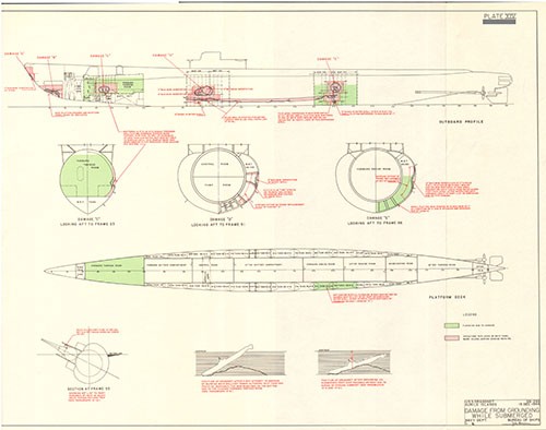
| XIV | DRAGONET | 293 | Grounding | Kurile Is. | 12/15/44 | 148 |
| XV | BEHAVIOR OF UNDERWATER NON-CONTACT EXPLOSIONS | 161 |
||||
| XVI | HULL DAMAGE AND STRENGTH | 177 |
||||
| XVII | STABILITY, BUOYANCY AND FLOODING | 193 |
||||
| XVIII | SHOCK PROTECTION | 203 |
||||
| XIX | ENGINEERING NOTES | 213 |
||||
| XX | PIPING | 223 |
||||
| XXI | HABITABILITY | 233 |
||||
| XXII | SUBMARINE ESCAPE NOTES | 239 |
||||
| XXIII | CONCLUSION | 248 |
||||
| APPENDIX I | BRIEFS OF DAMAGE INCURRED BY U.S. SUBMARINES DURING WORLD WAR II. | 250 |
||||
| APPENDIX II | TABULAR SUMMARY OF U.S. SUBMARINE LOSSES DURING WORLD WAR II. | 296 |
||||
| APPENDIX III | MAP COVERING AREA OF PRINCIPAL U.S. SUBMARINE OPERATIONS. | |||||
SECTION I
FOREWORD
1-1. This report is one of a series of sixty-two war damage reports prepared by the Bureau covering damage received in action by vessels of the U.S. Navy during World War II. It is the only report of the entire series which deals with war damage sustained by submarines. The remaining sixty-one reports cover cases of significant damage incurred by surface vessels, and include many instances of torpedo damage which may be of interest to submarine personnel who desire information on the destructive effect of their principal World War II weapon, the torpedo.
1-2. As a group, U.S. submarines have established an enviable record in combat, not only in destruction inflicted upon the enemy but also in their ability to sustain severe attacks without themselves receiving serious damage. Although the basic operational characteristics of our submarines remained substantially unchanged throughout the war years, with the notable exception of considerably increased maximum allowable submergence depth for the SS285 and subsequent Classes, marked advances were achieved in practically every other aspect of submarine and submarine equipment design. Improvements in shock protection have resulted in submarines which are highly resistant to damage short of actual destruction of their pressure hulls.
1-3. It is the purpose of this report, by presenting case histories selected from the great volume of war experience, to illustrate the behavior of U.S. fleet type submarines in service during World War II when subjected to enemy attack, and in particular, to attack by non-contact underwater explosive charges since the Japanese anti-submarine forces employed the depth charge and bomb as their principal weapons. Cases of damage by mine, torpedo, gunfire and collision are also included. An effort has been made to present a comprehensive summation of the effectiveness with which our submarines withstood attack, the materiel and design weaknesses revealed by war damage, the damage control problems attendant upon flooding of intact spaces or derangement of vital systems and equipment, and the corrective measures taken to reduce the vulnerability of our submarines to damage. It is hoped that the information presented here will be of value to submarine operating personnel and submarine design, repair and outfitting activities.
1-4. No attempt has been made in this report to evaluate the operational and military characteristics of our submarines in the light of War experience other than by statements of fact when such characteristics were impaired through war damage, nor have casualties incident to normal service operations been discussed. Lessons learned through the recent CROSSROADS OPERATION, and their possible effect on submarine design, have not been included.
--1--
2-1. The evolution of submarine design in this country has been unlike that of other naval vessels in that the early development was carried forward by private citizens, rather than by the Navy Department. Although the HOLLAND, completed by the Holland Torpedo Boat Company in 1898, was commissioned as our first submarine in April 1900, and numerous submarines were purchased from private concerns and added to the fleet in subsequent years, it was not until 1914 that the construction of a submarine was undertaken by the government. This was the L-8, built at the Navy Yard, Portsmouth, N. H., to the design of the Lake Torpedo Boat Company. It was not until late in 1916 that a complete preliminary design was prepared by the Navy Department for a submarine, the S-3. Commencing with the same vessel, the Navy Yard, Portsmouth was entrusted for the first time with the development of the detailed working plans as well as the construction. From 1919 until 1931 all submarines ordered were built to plans prepared by Portsmouth. Thereafter, the Electric Boat Company has prepared the working plans for all submarines built by it, while the Navy Yard, Portsmouth has prepared working plans for practically all submarines built in government yards.
2-2. The fact that two design agencies have been engaged in the development of submarines has led, it is believed, to more rapid progress than would have been accomplished by either of these agencies alone. Although each of the design agencies is allowed considerable freedom in the development of the details of a design, control is maintained in the Navy Department by virtue of the fact that the preliminary designs are prepared in the Navy Department, the contract plans are prepared in the Department or by an agency of the Department, and all working plans are subject to its approval. Thus, the best features developed by either agency may be incorporated into the designs prepared by the other.
2-3. By the year 1902, practicable solutions for the basic problems of submarine design had been achieved, at least in principle: i.e., electric motor drive with storage battery power for submerged propulsion; internal combustion engines for surface propulsion; the self-propelled torpedo as a means of inflicting damage on the enemy; a crude periscope for taking surface observations while submerged; and a satisfactory means of obtaining submerged control through the use of hydroplanes and variable ballast tanks. Subsequent development has been in the direction of refinement of design of the submarine as a whole and of its component parts, improvement in military characteristics and changes in design to keep pace with changed conditions of employment, rather than in the direction of changes in basic principles. One major innovation was the change to double-hull construction to improve seaworthiness through increased reserve buoyancy. The M-1, completed in 1918, was the first submarine of this type.
2-4. Commencing with the BARRACUDA Class of 1924 and continuing through the end of World War II, all submarines built by the U.S. Navy, with the exception of the 800 ton-type submarines MACKEREL (SS204) and MARLIN (SS205) completed in 1941, were of the fleet type, designed for high surface speeds and capable of operating for extended periods at sea and covering great distances. The submarine war effort of the United States was dependent almost entirely upon these fleet type submarines and for this reason only the damage experiences of fleet type submarines have been included in this report.
2-5. It is pertinent to mention that only negligible war experience was gained by our submarine service during World War I.1 The evolution of the fleet type submarine during the years of peace preceding World War II was the result of hypothesis and experience obtained through simulated exercises rather than actual war service conditions. The operating characteristics of the fleet type submarine proved adequate to carry the war to the enemy throughout the entire Pacific area, although great distances were involved.
2-6. U.S. submarine operations in the Atlantic during World War II were on a minor scale. Throughout the entire war only four enemy vessels were sunk by our submarines in the Atlantic, two of the four being German submarines, and but five other enemy vessels were damaged.2 Only one U.S. submarine was damaged in the Atlantic through enemy action.3 In the Pacific, however, where the major portion of our submarine effort was exerted, the U.S. submarine service established an impressive record almost from the first day of our entry into the war. Unrestricted submarine warfare against Japan was ordered by the Chief of Naval Operations on 7 December 1941. With the exception of a few special missions and support operations during the Battle of Midway and the initial phases of the Solomons Campaign, submarines were employed during the first two years of the war as free agents in a campaign of attrition against enemy combatant vessels and merchant shipping. With the inauguration of the Gilbert Islands campaign in November 1943, a gradually increasing percentage of the submarine effort was diverted to the support of fleet operations although normal offensive patrolling continued to the end of the war. The statistics of the Joint Army-Navy Assessment Committee credit U.S. submarines with the sinking of 54.6 percent of all Japanese naval and merchant vessel tonnage sunk during World War II by U.S. forces of all categories. The total of sinkings
___________
1 So far as can be determined, the first vessel credited as destroyed by submarine action in the history of the U.S. Navy was the Japanese cargo ship ATSUTASAN MARU (8,662 gross tons), sunk in World War II by SWORDFISH (SS193) on 16 December 1941, lat. 18° -06N., long. 109° -44'E. (credited by the Joint Army-Navy Assessment Committee, NavExos Publication P-468).
2 Submarine Operational History, World War II, prepared by Commander Submarine Force, U.S. Pacific Fleet (Preliminary Issue).
3 BLACKFISH (SS221), damaged by German depth charge attack in the Bay of Biscay on 19 February 1943. See brief of damage in Appendix I.
credited to U.S. submarines includes 201 Japanese naval vessels with a combined tonnage (standard displacement) of 540,192 tons, 29.6 percent of all Japanese naval tonnage sunk by U.S. forces, and 1113 merchant vessels above 500 gross tons with a combined tonnage (gross) of 4,779,902 tons, 60.4 percent of all Japanese merchant tonnage sunk by U.S. forces.1,2 The following numbers and types of combatant Japanese naval vessels were sunk by U.S. submarines: 1 battleship, 4 large aircraft carriers, 4 escort aircraft carriers, 3 heavy cruisers, 8 light cruisers, 38 destroyers, 23 submarines and 100 escort, patrol or mine vessels. In addition to the 1314 naval and merchant vessels credited as sunk, approximately 1000 Japanese vessels in all categories, with an estimated combined tonnage of over 5,000,000 tons, were damaged by U.S. submarines.3 It has been estimated that approximately 275,000 Japanese were killed as a direct result of Allied submarine operations.4
2-7. On 7 December 1941 there were 46 fleet type, 2 - 800 ton-type, 37 S-type, 18 R-type and 7 O-type submarines in commission in the U.S. Navy. Of these, 39 fleet type and 12 S-type were in the Pacific. On 15 August 1945, the day the war ended, there were 200 fleet type, 15 S-type, 10 R-type and 5 O-type submarines in commission. Of these, 169 fleet type and 13 S-type submarines were in the Pacific. A total of 202 fleet type submarines were completed and commissioned during the war.5
2-8. In all theatres during World War II, 269 U.S. submarines conducted a grand total of 1682 war patrols against the enemy. 251 submarines made patrols in the Pacific, of which 229 were fleet type boats and 22 were S-type boats. Of the total of 1682 war patrols, 948
____________
1 Japanese Naval and Merchant Losses During World War II by All Causes, NavExos Publication P-468 of 3 February 1947, prepared by the Joint Army-Navy Assessment Committee. The figures of this committee are very conservative as compared with the official statistics of the various force commands.
2 ONI Statistical Section (Op-32F-44) data credits German submarines with the destruction of 2,321 naval and merchant vessels of the United Nations, for a grand total of 12,866,711 tons, during the period from September 1939 to the German surrender in May 1945.
3 Submarine Operational History, World War II, prepared by Commander Submarine Force, U.S. Pacific Fleet (Preliminary Issue).
4 Figure given by Japanese to the Administrator, U.S. Naval Shipping Control Authority for Japanese Merchant Marine. (Submarine Force Pacific Fleet Bulletin, Volume III, Number I of February 1946.)
5 During the period from September 1939 to their surrender in May 1945, the Germans built a total of 1100 submarines, divided into the following categories: 912 attack type submarines which became operational; 119 Type XXI attack submarines which were delivered by the final assembly yards but none of which became operational due to hydraulic system defects; 10 experimental submarines; and 59 submarines designed for special service such as minelayers, cargo carriers and submarine tenders. - NavTechMisEu Technical Report No. 312-45 of August 1945 entitled "German Submarine Design, 1935-1945."
were conducted under the command of ComSubPac, 622 under the command of ComSubSoWesPac and 112 under the command of ComSubLant.
2-9. A survey of war patrol reports and other information available to the Bureau indicates that there were 110 separate instances, excluding losses, in which our fleet type submarines sustained damage from attack by either enemy or friendly forces where the damage received can be considered as more than negligible, or where the circumstances of the attack or the nature of the damage has been considered of sufficient interest to warrant mention. Brief accounts of each of the selected actions have been included in Appendix I of this report. The 110 cases of damage can be classified by cause as follows:
| Depth charge | 58 |
| Bomb | 25 |
| Depth charge and bomb | 8 |
| Aircraft strafing or small caliber gunfire | 6 |
| Medium caliber gunfire | 4 |
| Collision | 4 |
| Mass detonation of target ship | 2 |
| Mine | 1 |
| Kamikaze aircraft | 1 |
| Own torpedo | 1 |
| 110 |
Of these 110 cases, about 15 can be classified as resulting in severe damage, about 50 as resulting in moderate damage, and the remaining 45 as resulting in only minor damage.
2-10. In 49 of the above 110 cases, the submarines were forced to terminate their patrols as a result of the war damage received. In many of these instances, the damage which caused the termination of a patrol was restricted to but one vital system or equipment and the sum of all other damage was only minor or even non-existent. For example, in TROUT's (SS202) action of 3 October 1942, only the periscopes were damaged but this casualty alone forced the ship to return to base for repairs. It is difficult in many of the cases where war damage forced termination of patrols to assign any one or two specific items of damage as being responsible. When damage was widespread, even though each item may in itself have been fairly minor or capable of being repaired by ship's force, the cumulative effect of the total was often sufficient to force the boat to return to base for repairs. A review of the 49 war patrols which were terminated due to war damage indicates that the following classification by cause can be made:
| General severe damage | 15 |
| Widespread minor damage | 4 |
| Periscope damage (by explosion) | 5 |
| Periscope damage (by collision) | 4 |
| Medium caliber gunfire damage | 4 |
| Leakage rendering depth control difficult | 3 |
| Reduction gear damage | 3 |
| Conning tower door damage | 1 |
| Bow damage (collision) | 1 |
| Strafing attack | 1 |
| Derangement of stern planes | 1 |
| Conning tower plating failure | 1 |
| Control cubicle derangement | 1 |
| Oil leakage from external tanks | 1 |
| Contamination of hydraulic system with salt water | 1 |
| Damage to torpedo tube fittings | 1 |
| Damage to torpedoes | 1 |
| Small caliber gunfire (40mm) | 1 |
| Total | 49 |
2-11. Fifty-two U.S. submarines were lost from all causes during the period 7 December 1941 to 15 August 1945.1 A summary of these losses, with pertinent information where available, is presented in Appendix II. Of the total of fifty-two losses, at least nine were due to causes other than direct enemy action: four stranded on reefs during war patrols and were abandoned; two were lost due to operational or materiel casualties while on training exercises; one was lost by collision with a U.S. surface vessel while proceeding to her patrol area; and two were sunk by the malfunctioning of their own torpedoes. In addition, one was destroyed by Japanese bomb attack while under overhaul at Navy Yard, Cavite, P.I. The remaining forty-two submarines were lost at sea either through enemy action or for reasons unknown. The circumstances regarding the loss of six of these forty-two submarines are known from survivors' reports: two were scuttled after damage received by depth charge attack; one was scuttled after damage received by bomb attack; two were destroyed by mine explosions while running surfaced; and one was sunk by direct hits from medium caliber gunfire. The fate of the other thirty-six submarines is not definitely known. Assessment of the various sources of information enumerated in Appendix II of this report results in the following estimate: twenty-one submarines, probably or possibly sunk by depth charge and/or bomb attack; five probably or possibly sunk by mines; two possibly sunk by gunfire; one probably sunk by gunfire after being forced to the surface by depth charge attack; one probably destroyed, while surfaced, by Japanese torpedo attack; and six submarines whose loss remains in the unknown category.
__________
1 Enemy submarines destroyed from all causes in World War II totaled 996, including 781 German, 85 Italian and 130 Japanese. (Statistics compiled by the British Admiralty and United States Navy Department Assessment Committees. Intelligence received from enemy sources after the termination of the war was considered in this evaluation.)
2-12. Eleven cases of submarine loss or damage have been taken up in detail in this report and are grouped as follows: four cases of depth charge damage, including one loss; two cases of bomb damage, including one loss; one loss by torpedo damage; one case of damage by mine; one case of damage by medium caliber gunfire; one case of damage by collision and small caliber gunfire; and one case of damage by grounding while submerged. The cases have been selected to include not only the most serious instances of damage sustained by our submarines during World War II but also to illustrate the effect of underwater detonations at various points along the length of a submarine. The text of each case includes a narrative describing the action, the damage and its effect on the submarine, the damage control measures taken, the habitability aboard the submarine after damage, a discussion of the ordnance material which inflicted the damage, and such conclusions as may be drawn regarding materiel behavior.
2-13. Most of the information on the individual ship actions has been obtained from the respective Commanding Officers' patrol reports, the reports of war damage submitted by the Commanding Officers following the form of the Bureau's letter C-FS/L11-1(374); C-EN28/A2-11 of 17 April 1942 which was distributed to all vessels in the U.S. Navy, the supplementary war damage reports submitted by the various repair activities or Naval Shipyards, and survivors' reports in those cases where loss of the vessel occurred.
2-14. It is realized that the preparation of detailed reports during wartime often may be onerous to the individual concerned, especially when the press of other duties is extreme. However, it is through such reports that the forces afloat and field activities can keep the Department fully aware of significant developments and the need for design changes or materiel improvements. It is emphasized that reports of damage and loss have served as a basis for improvements in both design and equipment.
3-1. Much interesting and hitherto unknown information on the Japanese anti-submarine warfare effort was gathered at the end of World War II by representatives of the U.S. Naval Technical Mission to Japan.1 The most striking feature commented upon was the enormous gulf between the Japanese conceptions of such warfare and their actual accomplishments. The Japanese high command had given consideration to almost every phase of advanced anti-submarine warfare. Much thought and research effort was directed towards the development of echo-ranging equipment, influence and acoustic proximity-fuzed depth charges, deep-setting depth charge pistols, chemical recorders, ultra high frequency voice radio, surface search radar for escort ships and aircraft, magnetic detection equipment for aircraft, ahead-thrown rockets and standardized and improved doctrine for surface and joint air-surface offensive action. Satisfactory solutions to many of these problems were obtained and limited production of equipment and operational training were undertaken.
3-2. Nevertheless, at the end of the war Japanese anti-submarine warfare was still being waged without appreciable benefit from the results of their research effort. Lack of production facilities, inability to maintain adequate supply lines, and the necessarily large allocation of production to aircraft for the final defense of the Empire home islands greatly affected the anti-submarine forces, but there also existed a failure on the part of operating personnel to use what they did have to best advantage.
3-3. Although the importance of use of radar to detect submarines was recognized, many escorts were never fitted with surface search radar due to lack of equipment.2 Even those escorts which had been equipped with search radar and improved echo-ranging devices were in most cases unable to obtain satisfactory results, due to defective equipment and poor training of maintenance and operating personnel. However, both combatant ships and escorts were generally provided quite early in the war with effective directional equipment to detect radar being used by U.S. submarines. 2
3-4. The value of aircraft radar in anti-submarine work, both for search and blind attack, was also well recognized. Here again, their equipment was decidedly inferior and pilots generally were either poorly trained or lacked confidence in its use and are reported to have
___________
1 NavTechJap Target Report, Index No. S-24, of 8 February 1946 (Japanese Anti-Submarine Warfare).
2 Japanese anti-submarine escorts did not begin receiving radar surface search equipment in quantity until about September 1944. Previous to that date, very few escorts were equipped with search radar since most of the available production was allocated to combatant ships. Radar-detection receivers were installed on most escorts by April 1944. - U.S. Strategic Bombing Survey, Naval Analysis Division, Interrogation No. 61.
had but little success in radar bombing attacks. Airborne radar was first used in medium bombers as early as September 1943 but there was no large-scale employment of radar-equipped planes for antisubmarine work until the fall of 1944. Their equipment was reported to have been capable of detecting a surfaced submarine at a range of twelve miles. However, Japanese doctrine called for use of airborne radar only during night or low visibility conditions because visual search was still considered more reliable. Towards the end of the war, Japanese radar-equipped planes were making numerous contacts with our submarines but few attacks resulted. In 1945 a few antisubmarine aircraft were also provided with radar detection receivers but the Japanese professed to have never reached the stage of homing on U.S. submarine radar. However, war patrol reports indicate that at least some enemy pilots achieved moderate success in using such equipment for initially detecting the presence of our submarines. Precise locating was probably then accomplished with aircraft search radar rather than radar detection equipment.
3-5. By late in 1943, the Japanese had successfully developed a magnetic airborne detector (MAD) and, commencing in March 1944 this equipment was put into operational use by both the Army and Navy for anti-submarine patrol.1 Range of detection was reported to have been about 120 meters under average conditions and about 250 meters was claimed under ideal conditions. Since expert pilots flew magnetic search planes only thirty to forty feet above the surface, the apparatus was therefore presumably capable of detecting a submarine at well over 300 feet submergence. Aircraft equipped with MAD were employed principally to search ahead of convoys or to exploit a submarine contact made by other means. Although it was planned to use such aircraft to sweep all heavily travelled convoy routes, lack of both aircraft and MAD equipment prevented this. The instrument was considered sufficiently reliable to warrant calling in surface craft whenever an initial contact had been established. The types of planes normally used for anti-submarine work, and equipped with MAD and/or radar when possible, were NELL, JAKE, KATE, JILL, DAVE, BETTY, ZEKE and EMILY.2 By the end of the war only about one-third of the shore based anti-submarine planes had MAD, about one-third had radar, and only a very few were equipped with both. Anti-submarine planes were very seldom fitted with guns which accounts for the low incidence of strafing attacks against U.S. submarines.
3-6. Only one small land-based "hunter-killer" air-surface group existed and even this was not organized until early 1945.3 The group covered the East China Sea between Formosa and Shanghai and was comprised of five surface ships (DE types) known as the 102nd Surface Squadron and about 20 Navy fighters (ZEKES) of the 934th Squadron,
___________
1 NavTechJap Target Report, Index No. E-14 (Japanese Magnetic Airborne Detector).
2 U.S. Strategic Bombing Survey, Naval Analysis Division, Interrogations Nos. 200 and 371.
3 NavTechJap Target Report, Index No. S-24 (Japanese Anti-Submarine Warfare).
Shanghai Air Force. These planes were equipped with both radar and magnetic airborne detectors. For routine patrol, the planes usually carried two 60 Kg. depth bombs and when sent out to attack a previously detected submarine carried one 250 Kg. depth bomb, although the 250 Kg. size depth bombs were also sometimes carried on patrol. Both the planes and surface escorts were provided with voice radio but could communicate only for short distances and frequently were unable to communicate at all due to technical difficulties.
3-7. The Japanese repeatedly demonstrated facility in detecting and locating submerged submarines by using sonar. Their underwater listening gear was fairly good and could frequently pick up our submarines at ranges of 2000 meters or more when the listening ship was stopped or proceeding at very slow speed. A damaged submarine with a high machinery noise level, such as a reduction gear click, could of coarse be heard at a far greater distance than an undamaged submarine running silent or creeping. Their echo-ranging equipment was of mediocre design, roughly corresponding to the early U.S. QC sonar of about 1937. The emphasis which the Japanese placed on sonar devices is clearly shown by the unnecessarily large amount of space allocated to such equipment in the already cramped quarters of their ships. At sea it was customary to man the hydrophone set continuously and to operate the echo-ranging gear at least fifteen minutes in every hour. Small escorts were generally provided only with listening gear, in some instances just a crude hydrophone lowered over the side. Japanese scientists were cognizant of density layers and temperature gradients in sea water and their effect on sound transmissions in echo-ranging detection work. However, anti-submarine vessels were not equipped with bathythermographs and no tactical use was apparently made of the small amount of information of operational value issued by the Japanese Hydrographic Office.
3-8. The depth charge was the primary Japanese surface ship antisubmarine weapon. Depth charges were placed aboard practically every type of ship capable of carrying them and even the smallest of patrol craft could generally be expected to have a few. Very slow craft used parachutes to reduce the sinking rate of their charges so as to reach a safe distance from the detonations. The Japanese used depth charge throwers extensively and even merchant ships were occasionally equipped with these. Fleet destroyers generally carried about 30 depth charges. Frigates (KAIBOKAN) could carry as many as 300 and were usually fitted with twelve single depth charge throwers, six to a side, and one stern rack. The Japanese PC-13 Class, by far the most numerous of their PC types, carried about 36 charges with two side throwers and one stern rack. Gun armament for the PC-13 Class consisted of one 8 cm. dual purpose and one twin 13mm machine gun.
3-9. There were only two types of depth charges in general use by the Japanese for surface ship launchings and both were almost exact copies of early British models of obsolete design. These were the Type 95, the Type 2, and the various modifications of each.1
____________
1 Handbook of Japanese Explosive Ordnance, OpNav 30-3M of 15 August 1945 and Bureau of Ordnance Pamphlet 1507 of 20 April 1945.
The Type 95 was the regular issue depth charge until the development of the Type 2. Although the Type 2 charge was adopted in 1942, Type 95 charges are known to have still been manufactured up to 1943. Both charges were probably in use during 1943 until available supplies of the Type 95 were finally exhausted. The Type 95 depth charge was cylindrical in shape, 17.75 inches in diameter and 30.5 inches long. The Type 95, Mod. 0 was filled with 220 pounds of Type 881 explosive and a Shimose2 booster; the Mod. 1 with 325 pounds of Type 973 or Type 984 explosive; and the Mod. 2 with 242 pounds of Type 15 explosive. The Type 2 depth charge was also cylindrical in shape, 17.56 inches in diameter and 30.5 inches long. The Type 2, Mod. 1, was filled with 357 pounds of Type 97 or Type 98 explosive and the Mod. 2 with 242 pounds of Type 1 explosive.
3-10. The pistols for both the Type 95 and Type 2 depth charges were also almost exact copies of early British models and both operated on the same depth setting and firing principle, although they were not interchangeable between the two types of charges.6 The firing mechanism of both pistols was actuated by the hydrostatic pressure of sea water flowing through a small orifice and slowly filling up an inner cylinder. Depth setting was accomplished by varying the size of the water inlet, thus determining the amount of time required to fill the inner cylinder. The smaller the inlet, the deeper the setting. The Type 95 depth charge pistol used early in the war could be set for operation only at depths of 98 feet, 98 feet with parachute, 197 feet, and "Safe". Later modification of this pistol provided for an additional setting of 292 feet. The maximum range of depth settings for the Type 2 depth charge pistol was much greater, a choice being available of 98 feet, 197 feet, 292 feet, 390 feet, 480 feet, and "Safe". It was apparently not possible with either type pistol to choose depth settings other than those enumerated above, even though detonation at some intermediate depth might be considered desirable.
3-11 No data are available as to how much variation could normally be expected between the prescribed depth settings on the pistols and the depths at which charge detonation would actually occur. The amount of error would naturally be affected by variations in sinking rates due to the following factors: (a) the method of launching, i.e., whether the charges were projected from throwers or dropped from stern racks; and (b) by the condition of the sea, i.e., whether still or disturbed. The accuracy
____________
1 Type 88 explosive - 75% ammonium perchlorate, 16% ferro-silicon. More powerful than TNT. Power compares favorably with explosives containing aluminum.
2 Shimose - Almost pure picric acid. Slightly more powerful than TNT.
3 Type 97 explosive - 60% trinitrotoluene, 40% hexanitrodiphenylamine. Slightly less powerful than TNT.
4 Type 98 explosive - 60% trinitroanisole, 40% hexanitrodiphenylamine. Power is approximately that of TNT.
5 Type 1 explosive - 81% ammonium picrate, 16% aluminum. Power compares with that of Torpex or about one-third to one-half greater than TNT.
6 Handbook of Japanese Explosive Ordnance, OpNav 30-3M of 15 August 1945 and Bureau of Ordnance Pamphlet 1507 of 20 April 1945.
with which the orifices in the pistols were initially machined would also affect the detonation depth. Tests conducted by the British on their early pistols indicated that discrepancies of as much as 60 feet should be expected for charges set for detonation at 250 foot depth. It should be noted that even though a Japanese depth charge were to come to rest in water more shallow than that for which its pistol had been set, it would still fire when sufficient water had seeped through the entry orifice to provide the minimum pressure required. This is believed to account for many of the delayed depth charge detonations which have been reported by U.S. submarines.
3-12. The maximum depth setting possible with the Type 95 depth charge is believed to have been 292 feet and the maximum setting normally used for the Type 2 charge was 390 feet. A proportionate number of charges with these maximum settings were usually included in each attack pattern. Our submarines reported only a few cases where depth charges were set for depths in excess of 400 feet.1 As the Japanese were unable to estimate the depth of a submerged target, no specific technique was developed for attacking submarines that took refuge in deep submergence. The only deep setting depth charge pistol developed was the Type 3, Models 1 and 2, designed for operation at 131, 262, 393, 524 and 656 feet. 2 The design of this pistol was similar to that used in both the Type 95 and Type 2 depth charges but the extra time required to reach the greater depth was provided by a delay train initiated by the firing pin. However, issue to ships had not become general by the end of the war and no specific doctrine for its use had been developed.
3-13. Although the need for proximity-fuzed depth charges seems to have been appreciated, none were developed in time for operational use during the war. The Japanese Type 4 depth charge, designed for magnetic actuation, had been developed but trials on it were still in progress when the war ended.2 An acoustic type depth charge was also scheduled for development but work on this did not proceed beyond the preliminary design stage and no prototypes were made.
3-14. At least two types of anti-submarine explosive weapons designed for underwater tow by small surface vessels are known to have been developed and used by the Japanese, particularly early in the war. The first of these was called the "Yokosuka depth charge" and was set to explode upon contact with a submerged object. The charge was cylindrical in shape, about 1 foot in diameter by 5 feet in length, and contained 55 pounds of Type 88 explosive filler.3 The
____________
1 While being depth charged on 4 July 1944, during her fifth patrol, SEAHORSE (SS304) reported that her DGDI indicated a few charges were definitely detonating below the ship even though her depth at that time was 470 feet. THREAD FIN (SS410) reported that while being depth charged on 28 March 1945, during her second patrol, over half of the detonations occurred at depths greater than 450 feet as indicated by DCDI.
2 NavTechJap Target Report, Index No. 0-08 of 16 December 1945 (Japanese Depth Charges).
3 Handbook of Japanese Explosive Ordnance, OpNav 30-3M of 15 August 1945.
second weapon was designated by the Japanese as the Mark 2 Explosive Hook and, although developed primarily for minesweeping, was occasionally used for anti-submarine work. This device was a cast iron cylinder, 8 inches in diameter and ten inches long with four grapnel-like arms projecting from the main body, each 7-1/2 inches long. The body contained a charge varying from 8 to 19 pounds of Type 88 explosive.1 Firing was accomplished after the hook secured on a submerged target; the Mod. 0 either electrically by an observer on the towing ship or automatically when an additional tension of 550 pounds was put on the towing line, and the Mod. 1 by electrical control from the towing ship. Although several reports were received from U.S. submarines of small Japanese vessels apparently using these tow weapons, no large-scale employment was made and there is no information to indicate that damage was ever inflicted.2
3-15. Three sizes of aerial depth bombs were developed by the Japanese Navy specifically for anti-submarine work and were used for this purpose by both Army and Navy aircraft.3 These were designated by the Navy as Mark 2 bombs and by the Army as Type 4 bombs. They were fitted with anti-ricochet nose rings and had considerably higher explosive-loading factors than ordinary general purpose bombs. The smallest of the three was a 60 Kg. bomb, designated by the Navy as the Type 99, No. 6, Mk. 2, Mods. 0 and 1, and was loaded with 85 pounds of Type 98 explosive. These small bombs were carried primarily by planes on routine anti-submarine patrol and were considered to have a lethal range of 12 to 15 feet. The second was a 180 Kg. bomb designated as the Experimental 19, No. 25, Mk. 2, loaded with 308 pounds of Type 98 explosive. This bomb was developed primarily for use in conjunction with planes equipped with magnetic airborne detectors and was considered to have a lethal range of about 25 feet. The third and largest was a 250
____________
1 Handbook of Japanese Explosive Ordnance, OpNav 30-3M of 15 August 1945.
2 On 8 September 1943, during her first patrol, BILLFISH (SS286) sighted a Japanese convoy escorted by a small converted merchantman and a sampan, the latter dragging two cables over the stern. During the subsequent depth charge attack, a distinct scraping sound was heard down the port side of the hull while at a depth of about 300 feet. This probably was an explosive sweep. In at least two instances, U.S. submarines were caught by grapnels but managed to escape without damage. (a) While submerged off the entrance to Kwajalein on 9 July 1942, during her fourth war patrol, THRESHER (SS200) was hooked in her after superstructure by an unknown type of Japanese grapnel. It was reported that the pull of the grapnel line made the boat noticeably light aft. The grapnel was finally cleared, after ten minutes, by running at high speed with full right rudder and by increasing depth to 350 feet, (b) On her sixth war patrol, CREVALLE (SS291) was hooked in her periscope shears by a crude four-pronged grapnel. The grapnel line broke and the grapnel itself fell to the deck and was recovered upon surfacing.
3 Handbook of Japanese Explosive Ordnance, OpNav 30-3M of 15 August 1945 and NavTechJap Target Report, Index No. 0-23 of December 1945 (Japanese Bombs).
Kg. bomb designated as the Type 1, No. 25, Mk. 2, Model 1, Mods. 0 and 1, and was filled with 317 pounds of Type 98 explosive. This 250 Kg. bomb was considered to have a lethal range of about 33 feet and was generally only loaded on aircraft when a definite contact had been established by other planes or surface craft.
3-16. All three of the above Mark 2 depth bombs carried time rather than hydrostatic fuzes, and depth settings could only be varied by changing the fuze gaines prior to loading the bombs on aircraft. Four different fuze games with different time delays were used for anti-submarine work, each of which could be used with all standard Navy bomb fuzes, which in turn would fit any of the three Mark 2 bombs. The first game, the only variable setting design adopted by the Japanese, was designated as the Type 15 and could be set for detonation at any desired delay between 0 and 1.5 seconds after striking the surface of the water, equivalent to between 0 and about 50 foot depth.1 The desired setting had to be selected prior to insertion of the gaine in the bomb fuze. Although the Type 15 gaine was not developed specifically for anti-submarine bombs, it is known to have been used extensively for the purpose of attacking surfaced or submerging submarines. Each of the other three fuze gaines had a pre-fixed time delay and all three were designated as the Type 1, Mark 2 design. The Model 5 was set for detonation after 3.5 seconds delay, about 80 foot depth; the Model 1A after 6 seconds delay, about 150 foot depth; and the Model 1B after 17 seconds delay, about 300 foot depth.1 The Japanese referred to bombs fitted with the Models 5 and 1A gaines as "25 meter" and "45 meter" bombs and these were the types generally carried, although the gaines were naturally varied to suit the expected conditions.
3-17. When anti-submarine Mark 2 Navy bombs were not available, the Japanese substituted common types of 60 Kg. and 250 Kg. Navy GP bombs or Army 50 Kg., 100 Kg. and 250 Kg., Type 3 bombs. Army aircraft frequently carried a mixed load of their own Type 3 bombs along with Navy Mark 2 bombs, the Type 3 bombs being fuzed instantaneously, with short delays, or with a nose plug and a special 3.5 second delay tail fuze.
3-18. The Japanese directed considerable effort toward the development of gun projectiles for anti-submarine work which would continue an undisturbed trajectory after striking the water. After extensive tests in 1943, a flat-nosed projectile was adopted in which the area of the flat front was equal to half the area of the base. Projectiles of this non-ricochet type were produced for guns up to and including 8-inch.
3-19. Many U.S. submarines reported hearing small "sono-bomb" or "light" explosions while submerged and in contact with Japanese surface units. SALMON (SS182) likened the noise of such successive explosions to a "string of fire-crackers". These "sono-bombs" are believed to have been the Japanese Mark 3 and Mark 4 "Emit Sound Missiles" (HATSUONTO). This device consisted of a can 8 inches long and 5 inches in diameter, filled with Type 88 explosive. When dropped
____________
1 The time delays given here are based on U.S. tests and do not agree with the figures contained in Japanese documents. The depths corresponding to these time delays have been computed for bombs dropped from an aircraft traveling at 100 knots at an elevation of 100 feet.
into water, a small quantity of sodium under the top cap explodes, blowing the cap off and operating a pull igniter. Then after a short delay, the explosive charge detonates. These missiles were employed by the Japanese for the training of their own submarine crews, to simulate depth charges in an attempt to frighten Allied submarines away,1 and later were employed very successfully in sweeping U.S. - laid acoustic mine fields. Many of these "light" explosions heard just prior to depth charge detonations may also have been caused by the sound of depth charge throwers or possibly even gunfire in some cases.
3-20. Although mines were used by the Japanese as an anti-submarine measure and certainly constituted an appreciable hazard, such mining never became really extensive during any phase of the war, probably due to lack of mine-laying vessels.2 Both contact and controlled mine fields were laid in Empire coastal waters and harbors, the accesses to the Sea of Japan, the southern approaches to the Empire, Formosa and the Philippines. The most commonly used contact mine was the Type 93, containing 220 pounds of Type 88 or Type 1 explosive.3 This was a moored mine and was designed to arm only with tension on the mooring spindle, a drifting Type 93 mine therefore being disarmed except for those cases where the arming mechanism was locked closed by corrosion. The most commonly used controlled mine was the Type 92, containing 1100 pounds of Type 88 explosive.3 This was also a moored mine and could be either acoustically or magnetically monitored from shore or small vessels. The Japanese copied the design of two German magnetic and acoustic proximity-fuzed ground mines which were brought to Japan by a German vessel in September 1942 and produced their own adaptations by March 1944, both designed for planting by submarine. There is evidence that such mines were laid off Truk4 and in one area off the east coast of Australia2, but aside from these two locations there is no indication that proximity-fuzed mines were used anywhere else. The development late in the war of the QLA sonar mine detector made possible the penetration of enemy minefields by our submarines and permitted spectacular operations in areas long considered invulnerable by the Japanese, such as the Sea of Japan.
3-21. The greatest disparity between the weapons employed in the Japanese anti-submarine program and ours was their failure to develop an ahead-thrown contact weapon similar to our Mark 10 Projector ("Hedgehog"). Some development work was done on ahead-thrown rockets fired in salvos of five from "rocket guns" but results were not satisfactory and the project was abandoned. This was the only type of ahead-thrown anti-submarine weapon under consideration by the Japanese. The U.S. Mark 10 "Hedgehog." projectile is fuzed to detonate on contact and the charge size (33 pounds Torpex) is
____________
1 JICPOA captured Document No. 78745 records their use in this manner by a Japanese merchant ship and CinCPac-CinCPOA captured Item No. B-10202B also records such use by Japanese destroyers during the central action of the Battle for Leyte Gulf, 24-26 October 1944.
2 NavTechJap Target Report, Index No. 0-05 (Japanese Naval Mining Organization and Operational Techniques).
3 Handbook of Japanese Explosive Ordnance, OpNav 30-3M of 15 August 1945
4 Field Survey of Japanese Defenses at Truk, Part I, CinCPac-CinCPOA Bulletin 3-46 of 15 March 1946.
such that rupture of the pressure hull is to be expected even when detonation occurs at the superstructure. The tactical problem is simplified, for usually contact is not lost prior to launching of a "Hedgehog" barrage and no interference with sound apparatus will occur until a hit is obtained. Probability studies based upon the various factors entering into an attack on a submerged submarine and statistical analysis of action reports indicate that a submarine's chance of surviving a depth charge barrage are at least four times as great as the probability of surviving a "Hedgehog" attack.1
3-22. The Japanese failed to achieve optimum use of their principal anti-submarine weapon, the depth charge, simply by repeatedly setting their pistols too shallow. There are many instances reported by our submarines, especially during the first two years of the war, in which depth charge patterns detonated directly overhead without causing appreciable damage but where an increase in depth setting would probably have resulted in fatal or serious damage. Above all, the Japanese generally lacked persistence in both their search efforts and exploitation of a positive contact, once made. They were prone to accept the slightest evidence that a submarine had been destroyed and then depart. Many a U.S. submarine owes its escape to the Japanese predisposition to take the most optimistic view.
____________
1 From Operations Evaluation Group Report No. 51. This applies only to depth charges having pistols with preset depth settings, such as those used by the Japanese, and not to proximity-fuzed depth charges. An attack made with the latter is theoretically only slightly less effective than a "Hedgehog" attack.
U.S.S. PERCH (SS176)
Loss in Action
Java Sea
3 March 1942
| Class | SS173 |
| Builder | Electric Boat Co., Groton, Conn. |
| Commissioned | 19 November 1936 |
| Length (Overall) | 300 ft. 6-3/4 in. |
| Beam (Extreme) | 25 ft. 1-1/2 in. |
| Submergence Depth (Designed Maximum)(Axis) | 250 ft. |
| Displacements | |
| Standard | 1330 tons |
| Emergency Diving Trim | 1725 tons |
| Submerged | 2005 tons |
| Draft (Mean, Emergency Diving Trim) | 16 ft. 11 in. |
| Type of Propulsion | Diesel Electric Reduction Drive |
| Main Engines (4) | Winton 16-201A |
| Main Motors (8) and Generators (4) | General Electric Co. |
References:
(a) Enclosure (B) to ComSubsPacAdmin secret ltr. FF12-10(A)/A4-(1)/A16-2, Serial 00349 of 21 September 1945 (Commanding Officer PERCH Statement Concerning Loss of Vessel).
(b) ComSubsPacAdmin ltr. FF12-10(A)/A16-2, Serial 3599 of 12 October 1945 (Statements of Two PERCH Crew Members Concerning Loss of Vessel).
(c) ComSubsPac Report Entitled "Enemy Anti-Submarine Measures", no date or file number given (Account of Loss of PERCH).
(d) Account of Loss of PERCH as Related to Cdr. I.F. Duff, (MC), USNR, by Lt.Cdr. J.J. Vandergrift, Jr., USN, on 5 April 1946.
Photograph No. 4-1
4-1. On 2 March 1942, while operating in the Java Sea on her second war patrol, PERCH sustained severe depth charge damage which prevented further submerged operations and reduced her maximum surface speed to about 5 knots. Shortly after dawn on 3 March, PERCH was deliberately scuttled by her own crew to prevent imminent capture by Japanese surface forces. This report is based on the information contained in references (a) through (d). These references are accounts furnished from memory by various survivors of PERCH upon their release from Japanese prisoner of war camps at the end of the war, almost four years after the action took place. It naturally follows that the source data are not as complete and cannot be considered to have the same degree of accuracy as formal war damage and action reports written shortly after an action.
4-2. After normal refit, PERCH departed Port Darwin, Australia, for her second war patrol on 3 February 1942. At this time the Japanese campaign to secure the Netherlands East Indies was in full swing. PERCH was directed to patrol and perform reconnaissance in various positions in the Java and Flores Seas as part of the force then attempting to defend Java.
4-3. On the night of 25 February 1942, while patrolling the southern approaches to Kendaris, Celebes, PERCH sighted a Japanese supply ship and commenced approach for a surface attack. However, the enemy ship opened fire and scored one three-inch shell hit on PERCH which struck the light fairwater plating just forward of the conning tower proper and detonated inside the "doghouse". The pressure-proof radio antenna trunk and 200-pound air line to the whistle were ruptured, several electrical cables were cut by shrapnel, and the pressure-proof magnetic compass trunk system was flooded. Action was terminated without further damage. Temporary repairs were made by ship's force to the radio antenna trunk which permitted subsequent radio transmission.
4-4. The following night, PERCH was ordered westward into the Java Sea after a large Japanese convoy of troopships had been sighted near Bawean Island with apparent intentions of landing forces on Java. On 27 February, the Battle of the Java Sea occurred, ending all organized Allied surface resistance in the East Indies area. The Japanese landed on the northern coast of Java on 28 February. That night PERCH received notification of the exact landing point of the convoy and was ordered to disregard previously assigned areas and to attack.
4-5. On the next night, 1 March, PERCH was still proceeding west toward the designated landing area, and had reached a position about twelve miles northwest of Soerabaja, when two Japanese destroyers were sighted. PERCH was at this time running on the surface so she made a quick dive to avoid detection. There was a full moon and visibility conditions were excellent. The destroyers passed well clear astern and out of torpedo range but turned back after proceeding about four or five miles. One of the destroyers then came in close
on a course favorable for stern torpedo shots and PERCH made ready for attack, taking frequent periscope observations. However, on the last periscope check before firing, it was noted that the target destroyer, which was distant about 800 to 1000 yards at this time, had obviously detected PERCH and was charging in at high speed for an attack.
4-6. The Commanding Officer, believing he was in 200 feet of water, immediately ordered depth increased to 180 feet. When PERCH had reached a depth of about 90 to 100 feet, however, the destroyer passed directly overhead and dropped several depth charges. This first pattern was not close and caused no appreciable damage. Shortly afterwards, PERCH struck bottom at about 147 feet depth with her propellers still turning over and while in this position received a second pattern of four depth charges, this time very close. This group of charges was apparently dropped by the second destroyer. Considerable damage was sustained aft and all main motor field relays tripped, causing temporary loss of propulsion. While still on the bottom, a third and final depth charge pattern was received very close aboard amidships. The enemy destroyers then ceased further attacks, apparently convinced that PERCH had been destroyed, although they remained in the immediate area.1
4-7. Extensive damage was caused by the second and third depth charge patterns. As mentioned previously, all main motor field relays tripped, causing temporary loss of propulsion until they were reset. The pressure hull was dished inward by as much as 2-1/2 inches in the after battery compartment on the starboard side forward and the port side aft. The conning tower plating was depressed to a depth of about 2 inches over an area about three feet by one foot. The engine room hatch, conning tower hatch and conning tower door gaskets were crimped and leaked steadily. The inboard hull flapper valves for the ship's supply ventilation system and the engine air induction system were jammed closed. MBT No. 5 master vent valve also jammed in the closed position. The battery exhaust system outboard valve apparently opened momentarily upon one or more close detonations and sea water flooded the exhaust duct section in the control room, some of it splashing onto the fire control panel. The high pressure air bank in the after battery well commenced to leak heavily. Both main batteries showed full ground. No. 2 periscope could not be moved. No. 1 periscope could be raised and lowered but required the combined effort of four men to train it. Ninety per cent of the gauges and instruments in the engine room were broken or deranged and several depth gauges were also put out of commission. Considerable inboard leakage occurred through a cracked weld at the hull flange of the air conditioning circulating water supply system.
____________
1 A list of anti-submarine attacks, received from the Japanese at the end of the war, which were assessed as resulting in "positive" sinkings, mentions several attacks in this area on 1-2 March 1942 but no amplifying data was submitted and none can be definitely identified as having been made on PERCH.
4-8. It is interesting to note that although this first series of attacks was sufficiently severe to cause considerable permanent hull deformation, the watertight integrity of the hull proper remained substantially intact and no serious damage was sustained at this time by either the submerged propulsion plant or vital auxiliary systems and equipment. It is probable that all of the depth charges were set for detonation at 98 feet since the next deeper setting available on Japanese charges was 197 feet and the depth of the water in which the attack occurred was reported to have been only about 150 feet, a fact certainly known to the enemy.
4-9. Shortly after receiving the third depth charge pattern, PERCH got underway again and by using evasive tactics managed to lose both destroyers in about two hours. At about 0300, 2 March, PERCH surfaced and an inspection topside was made. All the radio antennae insulators were found to have been broken. An armful of fragments from the depth charge cases was picked up on deck. Both periscope head windows were shattered and both periscope tubes had completely flooded. The bridge blinker light was found compressed flat.
4-10. No. 1 main Diesel engine ran away on starting and the camshaft of No. 4 main engine was found broken, leaving only two main engines in operating condition. No. 2 main engine was put on battery charge and No. 3 main engine was put on propulsion. PERCH once again proceeded in the direction of the Japanese landing on Java, still with intentions of attacking the enemy. Repairs to damage were started where possible and the high pressure air banks were replenished.
4-11. At about 0400, approximately two hours before sunrise, the same two Japanese destroyers were again sighted. PERCH immediately submerged and lay on the bottom in about 200 feet of water with all machinery secured. This course was chosen rather than evasive running for the machinery had developed a high noise level as a result of the previous attack and it would have been necessary to use the very noisy trim pump almost constantly in order to maintain depth control.
4-12. Unfortunately, the enemy destroyers had either sighted PERCH before she submerged or had established definite sound contact, for several depth charge attacks were immediately delivered, resulting in serious damage. An attempt was then made to get under way and take evasive action but the propulsion plant was found to be inoperative, due to short circuits in the electrical control gear or damage to the main motors, and PERCH was forced to remain on the bottom. Following this series of attacks, the enemy destroyers apparently decided to postpone further efforts until daylight but in the meantime made frequent checks on PERCH's position by echo-ranging.
4-13. Shortly after sunrise, three more attacks were delivered, the final pattern of three charges at about 0830 being the most severe of all. The enemy destroyers then left the area, probably again certain that they had destroyed their target.
4-14. Reference (b) reports that "there was hardly any part of the boat that had not in some way been damaged." Only one of the four main Diesel engines was not damaged beyond immediate repair. However, the two auxiliary engines (Winton 6-241) were still operable. The port reduction gear casing was cracked and lost lubricating oil constantly. As mentioned above, the submerged propulsion plant was put out of commission due to deranged control equipment and motor damage. Numerous holding down bolts on the main motors, main generators and main engines were reported to have broken.
4-15. The pressure hull overhead in the forward battery compartment was dished inward to a depth of about 1-1/2 inches over an area of about 6 feet by 2-1/2 feet and many other new indentations occurred at various points along the length of the ship in addition to those received from the first series of attacks. In no place, however, was the pressure hull torn or ruptured.
4-16. All lighting was cut off by a close detonation but was partially restored after a short while. Many auxiliary motors were short-circuited or deranged. There were at least nineteen cracked jars in the forward battery and one in the after battery, causing loss of electrolyte and full grounds. All of the electric alarm and telephone circuits were out of commission.
4-17. One particularly close detonation forward caused the bow planes, then on 20 degrees rise angle, to partially rig in, damaging the bow plane rigging system. The holding down studs for the bow plane tilting motor backed off or elongated and the shims dropped out. The planes were thereafter tilted by hand. The radio antenna trunk flooded. The JK sound head was put out of commission. Torpedoes loaded in forward tubes Nos. 1 and 2 and one torpedo loaded in an after tube were reported to have made "hot" runs. Many torpedo tube doors were jammed. All water closet bowls (porcelain) were shattered. The engine room deck support stanchions were torn away at their overhead connection to the pressure hull.
4-18. Both Nos. 1 and 4 high pressure air banks bled completely down through numerous leaks and various other air system leaks developed throughout the boat. The increase in pressure of the atmosphere within the boat from these air leaks was considerable although it could not be measured since the barometer was broken. The excessive air pressure, extreme heat, and high humidity caused much discomfort and had a deleterious effect on all hands.
4-19. Sea water leakage into the pressure hull also increased markedly. Strips a quarter of an inch square in cross section had been cut from the conning tower and forward escape trunk door gaskets. Leakage around these doors and the conning tower and engine room access hatches became serious. The air conditioning circulating water supply hull flange crack, caused by the first series of attacks, became enlarged and the flange studs elongated or the nuts backed off, further augmenting the leakage at this point. Many
other salt water systems throughout the ship also developed leaks. Fuel tanks are reported to have leaked externally.
4-20. PERCH remained on the bottom until after sunset on the evening of 2 March. Order was restored and repairs to equipment were attempted where possible during this period. Damage to one of the main motors was isolated and battery propulsion was regained on both shafts. Bilges were kept pumped down to avoid grounding electrical machinery. The forward and after trim tanks and No. 2 auxiliary tank were pumped dry.
4-21. At about 2000 on 2 March, after approximately sixteen hours submerged, the first attempt was made to surface. The boat did not move, however, for the downward thrust of the depth charge attacks had partially embedded the hull in the soft ocean floor and many master vent valves leaked or could not be seated, rendering it impossible to blow the ballast tanks since air introduced into the tanks escaped through the risers. As an indication that the boat had been forced deep into the soft bottom, it was noted during the final severe depth charge pattern that PERCH's remaining depth gauge suddenly changed reading from 200 feet to 228 feet and then to 230 feet, although this might have been due to derangement of the gauge itself.
4-22. By closing the emergency vent valves and going alternately ahead and astern at maximum revolutions on both shafts, PERCH finally broke loose from the bottom on her third attempt. These efforts consumed a period of about one hour and all high pressure air was expended except for one partially filled bank. The enemy was not in sight upon surfacing.
4-23. After successively attempting to start all four main engines, only No. 3 engine was found operable and PERCH got under way at a speed of about 5 knots. About half of the holding down bolts for the No. 3 engine had broken and the engine vibrated so badly that the head covers raised one inch. The batteries were put on charge with the undamaged auxiliary Diesel generators. The steering gear was behaving erratically at this time, for the rudder could be moved from the full left position only with difficulty and upon reaching amidships would suddenly snap over hard against the starboard stops. MBT No. 2 was leaking heavily from sea. Even on the surface, sea water leakage into the hull was sufficient to keep both the trim and drain pumps operating at full capacity. All gyro-repeaters had been deranged and steering was accomplished by relaying word to the bridge from a man stationed at the master gyrocompass in the control room. Many depth charge case fragments were again found on the deck topside.
4-24. After quickly surveying the condition of the boat, the Commanding Officer at this time set up procedure for scuttling the ship if it became necessary. Repairs were attempted where feasible. Men working in the engine room were unable to tolerate the extreme heat and had to be relieved frequently so they could go topside to recover.
4-25. PERCH continued to run on the surface throughout the night. In order to determine whether or not the boat could submerge, it was decided to try a running dive while still dark. This was attempted about an hour and a half before sunrise on 3 March. However, in spite of having deliberately tried to make the ship light so that trim could be established by flooding in on the dive, PERCH was found very heavy aft. The boat assumed a large up angle and water entered in large volume around the conning tower and engine room hatches which failed to seat properly. When a depth of 75 feet had been reached and the two hatches still showed no sign of seating themselves by hydrostatic pressure, the boat was surfaced. Reference (a) reports that at this time there was still only one full air bank. By the time PERCH reached the surface, the water level in the engine room bilges was almost to the main generators.
4-26. It was found that the conning tower hatch lacked complete seating by a gap of about 3/8 inch. The hatch dogs were removed and adjusted but with no improvement. This work was handicapped by the necessity of having to keep the ship darkened to avoid detection. Once again the dogs were removed, but while attempting further adjustments, three Japanese destroyers came upon the scene and opened fire on PERCH. Five or six shells landed in the water nearby.
4-27. PERCH attempted to engage the enemy with her three-inch deck gun but it could neither be trained nor elevated and the sights were shattered. Torpedoes could not be fired. In this helpless condition, with no fire power, obviously unable to submerge and capable of making only 5 knots on the surface, the Commanding Officer decided to abandon and scuttle the boat at once. All hands were ordered topside. The diving alarm was sounded and the vents were opened by one officer who had remained below for this purpose. The men on deck literally felt the ship, which was still going ahead at one-third speed on her batteries, go out from under them. All the men leaving the ship were equipped with life jackets and some in addition carried escape "lungs" and flashlights. The officer who manned the vents had to fight his way out through the open conning tower hatch against the incoming water. PERCH went down about 100 yards from the survivors shortly before dawn on 3 March 1942, with her colors flying.
4-28. As far as is known, the entire crew was taken aboard by the Japanese destroyers during the morning. Most of the survivors were imprisoned until the end of the war at Makassar, Celebes, although a few were later transferred to various camps in Japan. Fifty-three officers and men are known to have survived to the end of the war.
4-29. In analyzing the many factors involved in the loss of PERCH, it appears that the conning tower and engine room hatch damage was the only reason the boat was unable to submerge upon sighting the enemy destroyers on the morning of 3 March. This case is an excellent illustration of the unhappy fact that but one casualty to a vital part of a submarine can cause its loss.
4-30. However, even had PERCH been able to submerge, it is problematical whether she could have escaped eventually. For example, the extent of external leakage from the oil tanks is not known. This alone might have been sufficient to disclose her exact location to the enemy and in such shallow waters it is likely that she would not again have survived a series of well executed depth charge attacks. Even had the destroyers not discovered PERCH on the morning of 3 March, in the event that repairs could not be made to the damaged hatches it is doubtful that she could have made a surface escape with only one engine, for the Java Sea was at this time completely controlled by the Japanese.
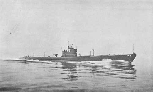
U.S.S. KINGFISH (SS234)
Depth Charge Damage
Off Formosa
23 March 1943
| Class | SS212 |
| Builder | U.S. Navy Yard, Portsmouth, N. H. |
| Commissioned | 20 May 1942 |
| Length (Overall) | 311 ft. 8 in. |
| Beam (Extreme) | 27 ft. 3 in. |
| Submergence Depth (Designed Maximum)(Axis) | 300 ft. |
| Displacements | |
| Standard | 1525 tons |
| Emergency Diving Trim | 2050 tons |
| Submerged | 2415 tons |
| Draft (Mean, Emergency Diving Trim) | 16 ft. 10 in. |
| Type of Propulsion | Diesel Electric Reduction Drive |
| Main Engines (4) | Fairbanks-Morse 38-D-8-1/8 |
| Main Motors (4) and Generators (4) | Elliott Co. |
References:
(a) C.O. KINGFISH conf. ltr. SS234/A12-1/A-16-3/A9 of 8 April 1943 (Report of War Patrol Number Three).
(b) Comdt. Navy Yard Mare Island conf. ltr. SS234/L11-1 (33-558674) of 17 May 1943 with enclosures thereto (Supplementary Report on KINGFISH War Damage).
(c) BuOrd (Re6) Memorandum dated 4 May 1943 (Report on Inspection of KINGFISH Damage and Interview of Ship's Officers by Dr. A. B. Focke).
Photographs Nos. 5-1 through 5-16 (furnished by Navy Yard, Mare Island).
PLATE V
5-1. On 23 March 1943, while on her third war patrol, KINGFISH underwent a severe depth charge attack north of Formosa. A total of over forty depth charges were dropped in the vicinity of KINGFISH during the 7-1/2 hour period she was under attack. Serious damage was caused by the final pattern of six charges, two of which detonated close over the after portion of the ship while the boat was running at 300 foot depth, forcing her to the bottom in 350 feet of water. In spite of sustaining considerable permanent pressure hull deformation in various areas and widespread interior damage, no vital systems or machinery were put out of commission and watertight integrity remained substantially intact. Six hours after the termination of the attack, and without undue difficulty, KINGFISH was able to surface and clear the area at full power on all main engines. This report is based on the information contained in the references and on an informal interview with the then Commanding Officer. The Photographs were furnished by the U.S. Navy Yard, Mare Island. The PLATE was prepared by the Bureau from data contained in the enclosures to reference (b).
5-2. KINGFISH arrived at Pearl Harbor from her second war patrol on 23 January 1943. Normal refit was undertaken by repair forces of the Submarine Base, Pearl Harbor, and completed on 7 February. Deperming, sound tests and training were completed on 15 February and, on 16 February, KINGFISH departed Pearl Harbor for Midway, arriving on 20 February. Minor voyage repairs were made there and fuel and lubricating oil were topped off. She departed Midway on 21 February for her third war patrol and arrived on station in the wafers adjacent to the Island of Formosa on 7 March, destroying a 250-ton enemy trawler by three-inch gunfire attack on 4 March while en route. On 17 March KINGFISH sank a medium-sized freighter by two torpedo hits during a night submerged periscope attack and on 19 March sank a medium-sized troop transport by two torpedo hits during a daylight submerged periscope attack. Three other attacks were made but no hits were obtained, apparently due to faulty torpedo performance.
5-3. At 0300 on 23 March, while surfaced about 60 miles north of Formosa, lat. 26° 20' N., long. 121° 55' E., KINGFISH sighted at a range of approximately 5000 yards what appeared to be either a small Japanese destroyer or minelayer of about 1200 tons. Battle stations were manned at once and an attempt was made to gain a position ahead of the enemy ship for a dawn attack. However, at 0325, the target ship detected KINGFISH and headed toward her at a speed of about 16 knots. KINGFISH was able to draw away slowly at flank speed but twenty minutes later, at 0345, the enemy illuminated her with a searchlight. At this point, KINGFISH submerged to a depth of 250 feet, rigged ship for depth charge attack and silent running, and commenced evasive action.
5-4. These maneuvers were unsuccessful, however, for at 0448 KINGFISH received the first of a long series of depth charge attacks.1
____________
1 A list of anti-submarine attacks received from the Japanese at the end of the war, and assessed as resulting in "positive" sinkings, contains no mention of this series of attacks on KINGFISH.
Evasive tactics were continued at a depth of 300 feet but the enemy was both tenacious and experienced, and seemed to have no difficulty maintaining contact. He appeared to use sonic listening for determination of azimuth and echo-ranging for distance. Sound conditions were excellent. Three attempts were made by KINGFISH to approach the surface and fire circular run torpedo shots, but each time the enemy counterattacked before a depth of 100 feet was reached and this plan had to be abandoned. At 0752 the screws of a second ship were heard. This vessel took no direct action, apparently having no depth charges, and used no sound gear other than a fathometer. A total of 41 depth charges in eight separate patterns were dropped during the entire 7-1/2 hour period KINGFISH was under attack. Attacks were spaced at about one hour intervals and consisted of from 3 to 8 charges each.
5-5. No serious damage was sustained until the final attack at 1227, at which time a pattern of six depth charges was received very close aboard while the ship was running at 300 foot depth. The charges were dropped in pairs, the first two detonating over the after portion of the ship, dishing in the pressure hull and forcing KINGFISH to the bottom in about 350 feet of water. The second pair of charges detonated forward of and above the ship, causing but little damage. The third pair of charges was delayed nearly a minute and detonated forward, also causing only minor damage. Following this attack the enemy vessels stayed in the vicinity for several more hours, occasionally making transits across KINGFISH, but did not drop any additional charges.
5-6. The two close detonations aft, at 1227, caused severe vertical flexural vibrations of the hull as a whole. Reference (a) reports that the ship "humped like a measuring worm" and was forced considerably off her course. Reference (c) notes that there were "three strong up and down vibrations, followed by gradually decreasing ones". This type of vibration had not been observed during any previous depth charge attacks experienced by KINGFISH. The motions were of such magnitude as to throw two men from their bunks to the deck and other personnel lost their footing even though braced in anticipation of shock. Some 12 of the 41 charges dropped on KINGFISH were close enough to cause at least minor damage. The more distant of these 12 charges broke lights, stopped clocks, jarred cork insulation from the hull and, in general, caused lightly attached hull fittings to come loose. Closer-in charges caused numerous hull valves throughout the boat to open. Two observers claimed to have seen flame shoot past the breech door of one of the after torpedo tubes coincident with the detonations of the two very close depth charges aft. Smoke and fumes were also detected in the after torpedo room.1
5-7. All of the depth charges dropped by the enemy were probably of the Type 2, Mod. 1 design containing 357 pounds of Type 98 explosive. The two close detonations aft at 1227, which were responsible for most of the damage, are believed to have been centered as follows: One charge at the after end of the ship about ten feet above the deck level, causing the phenomena observed at the torpedo tube and forcing the
____________
1 For further discussion, see paragraphs 15-18, 15-19 and 15-20.
stern down with resultant plating failure under compression at the lower outer hull between frames 103 and 108; the second charge approximately 40 feet directly above the hull at about frame 83, causing the pressure hull structural deformation which occurred in way of the forward engine room.
5-8. Upon being forced to the bottom, the ship was silenced completely and, while awaiting darkness, the crew made temporary repairs to damage where feasible. Plans were prepared for scuttling ship in case escape proved impossible after surfacing. In partial execution of these plans, the ECM was destroyed and the torpedo data computer was rendered inoperative by disabling the forward angle solver. Only two after effects of the attack caused serious concern at this time. The first was the profuse leakage of sea water which occurred in both engine rooms through the distorted engine induction hull valves, the external induction system having completely flooded. This leakage was almost completely stopped within 15 minutes by forcing the valves hard against their seats with the aid of chain falls. The second was the high pressure air leakage into the boat through a damaged fitting in the No. 3 air bank piping and at partially opened cone joint connections at the high pressure air manifolds in the control room. The air pressure within the boat increased markedly as a result of this leakage. Since all manometers and barometers were disabled, the amount of increase in air pressure could not be determined but calculations indicate that it was of the order of eight or more pounds per square inch.
5-9. At 1500 and again at 1800 the screws of an enemy vessel were heard plainly through the hull for periods of about 15 minutes although no more depth charges were dropped. At 1848, after dark, KINGFISH manned battle stations and surfaced. A patrol vessel of about 1000 tons was sighted lying-to approximately 2000 yards off the starboard bow. No difficulty was experienced in immediately getting underway and the area was cleared at flank speed using all four main engines. Fortunately no opposition was encountered from the enemy patrol craft.
5-10. Since the damage made further offensive action impossible, KINGFISH returned to base for repairs, arriving at Pearl Harbor on 9 April 1943. The return run was made submerged during daylight hours for the first two days. The only difficulty encountered in these submerged operations was the minor leakage into the engine air induction system and the complete flooding of the ship's supply ventilation system outboard piping which occurred on each dive.
5-11. Damage to the ship was of varied nature and of general extent throughout (PLATE V and Photos 5-1 through 5-16), but was most severe in the vicinity of the forward and after engine rooms, conning tower, and after torpedo room. Structural damage in these areas consisted of minor distortion to the circularity of the pressure hull and numerous depressions of the hull plating between frames. Damage in way of the engine rooms extended from frames 77 to 93, with the more
severe depressions occurring in the upper pressure hull plating between tank tops from frames 80 to 87. Depressions of 1-1/4 inch maximum depth occurred at frame 86 on the forward engine room riveted access patch and between frames 82 and 83 (Photos 5-1 and 5-3). The keystone frame connections at frames 85 and 86, in way of the hard patch, pulled slightly apart due to depression of the hull in this vicinity (Photo 5-2). Although the riveted butt and seam connections appeared to be the weakest points of this hard patch, it is significant to note that only minor leakage developed around the rivets in spite of the considerable distortion and impact to which this region of the hull was subjected. Small leaks also developed around the forward and after battery compartment bolted access patches, although these were remote from areas of hull damage. Except for the minor distortion which occurred to frame 83 (Photo 5-3), all frames appeared to retain their proper shape.
5-12. Local depressions of the outer shell plating up to a maximum depth of about 1 inch occurred between frames, port and starboard, in way of three after lubricating oil tanks as follows: motor and reduction gear lubricating oil sump tanks Nos. 1 and 2, "A" strake (30-pound MS) between frames 103-105; motor and reduction gear lubricating oil stowage tank, "A" strake (30-pound MS) between frames 105-107; engine lubricating oil stowage tank No. 5, "B" strake (20-pound MS) between frames 107-108 (PLATE V, Photo 5-4). These areas are subject to full sea pressure and were structurally somewhat weaker than corresponding outer hull structure in way of the auxiliary and safety tanks. The depressed areas of the "A" strake between frames 104-106 occurred in 30-pound plating backed by frames spaced on 30-inch centers instead of 24-inch centers as in the auxiliary and safety tanks and the "B" strake depressions between frames 107-108 occurred in way of 20-pound plating on 24-inch frame spacing instead of 30-pound plating as in the safety and auxiliary tanks.1 The deformations in these areas could have been caused by either direct explosive loading from a close detonation or, possibly, as a result of the strong flexural vibrations reported by the ship, the depressed area occurring at the quarter length or natural node of vibration of the ship's structure as a whole.
5-13. Farther aft, minor depressions occurred in the shell plating just above the stern tubes, port and starboard, and the top of the after trim tank was indented to a depth of approximately 1 inch in two small areas, port and starboard, between frames 127 and 128. The trim tank depressions were located at the points where the port and starboard propeller guard struts had been originally attached. These guards had previously been permanently removed on KINGFISH when it was found that the plating in way of the strut attachments had cracked, due to vibration. The cracks were welded up and covered with small doubter plates, causing local hard spots in the structural continuity, and this probably accounted for the local deformation at those points. The trim tank did not leak, however.
____________
1 While not critical, as a result of KINGFISH's experience it was considered that the outer hull plating in these areas should be reinforced. ShipAlt SS192 of 19 May 1943 therefore authorized the installation of 20-pound MS doubters in way of these lubricating oil tanks on SS18-284. SS285 and subsequent submarines were designed with heavier plating in these areas.
5-14. Investigation of the ship's structure in the after torpedo room disclosed minor variation from the designed offsets and the top of MBT No. 7 was dished upward between frames 110 and 118 to a maximum of 15/32 inch. No evidence of buckling of the tank top stiffeners could be found, however. The movement of the tank top forced the torpedo stowage and loading tracks out of alignment with the torpedo tubes to such an extent that they later had to be cut adrift and reset. The MBT No. 1 tank top plating in the forward torpedo room was also pushed upward, but to a lesser extent. However, realignment of the forward torpedo tracks was also found necessary in order to secure satisfactory torpedo handling and loading.
5-15. Both the end bulkheads and shell plating of the conning tower cylindrical structure sustained permanent deformation. The conning tower bulkheads installed on KINGFISH at this time were of the type having a 15-pound medium steel inwardly dished plate acting as the bulkhead proper with a heavy forged ring connecting the periphery of the dished plate to the cylindrical wrapper plate (Photo 5-5). It was reported by the ship's officers that the forward bulkhead was initially forced in to such an extent that the steering wheel moved approximately two inches aft relative to the lockers on the port side, and that the locker drawers could not be opened due to interference with the wheel. During the trip back to base, however, the ship reported that the amount of bulkhead deformation gradually reduced until, upon arrival, it was only about one-third the original amount. Offsets taken at the Navy Yard, Mare Island, one month after the damage occurred indicated a variation from the designed offsets of only 1/2 inch at the forward bulkhead and 3/4 inch at the after bulkhead. These figures mean little, however, since the dished plates are frequently shaped with at least that much deviation from the designed radius of curvature.1 No means were available for determining the actual bulkhead offsets as originally fabricated and installed at the building yard. It is certain, however, from the known change which occurred in the relative positions of the steering wheel and lockers, that the forward bulkhead was deformed considerably.
5-16. It is interesting to note that the 20-inch by 38-inch six-dog watertight escape door fitted in the after bulkhead of the conning tower remained substantially intact and that no leakage occurred in spite of the probable large bulkhead deflection. The door frame was sufficiently distorted, however, so that the door dogs bound against the seat and prevented the door from opening more than a few inches (Photo 5-5). It was fortunate that the door seat was wide and flat, for had it been narrow or rounded, as was the case with earlier designs, the door gasket very probably would have been cut or blown out when the bulkhead deformed and serious leakage into the conning tower would have resulted.2
____________
1 Allowable tolerance from designed radius of curvature for such bulkheads was plus one inch and minus nothing - BuShips dispatch 122222 of June 1943.
2 As a result of this casualty, similar war damage experiences of other submarines, and tests conducted at the Navy Yard, Portsmouth, conning tower doors were removed on all submarines per BuShips ltr. SS/S16-2(515) of 30 April 1943. This was accomplished on ships in service by completely renewing the after bulkhead of the conning tower. Such doors were omitted from the designs for SS285 and subsequent submarines.
5-17. The conning tower plating was slightly deformed at the top after portion of the cylinder. The maximum depression occurring in this region was only 3/8 inch, located between the after bulkhead forged ring and the hoop stiffener just forward. Cork insulation under the depressed areas was cracked and loosened. A check of the general circularity of the conning tower cylinder showed that it conformed to the designed allowable diametrical tolerance of one-half the plate thickness.
5-18. Damage to structure and fittings external to the pressure hull was negligible. Two eyeports in the pilothouse were shattered and the light access door leading from the pilothouse to the forward gun platform was sprung so that it was difficult to close. The after torpedo room deck loading skid was jarred loose and lost overboard. No other damage worthy of mention was sustained by the superstructure, conning tower fairwater or bridge.
5-19. Damage to external hatch covers occurred in only two places. The forward escape trunk upper hatch cover was warped downward sufficiently to partially unseat itself and the trunk completely flooded. The hatch dogging mechanism was also bent, apparently when the cover was forced up under the action of one or more depth charges. Although the trunk flooded, the lower hatch held tight and no water entered the ship. No damage was sustained by the after watertight door of this escape trunk. The upper conning tower hatch cover seat was found to be distorted slightly but no leakage occurred. An interesting minor effect of depth charge impact was that the pins securing the upper handwheels to the squared ends of the worm shafts sheared off on both the forward and after escape trunk hatches. Aside from the conning tower bulkhead door frame, previously mentioned, no other damage occurred to external hatches, seats, gaskets or operating gear. However, the transverse struts fitted at the forward and after torpedo loading hatch bosses showed evidence of excessive compression, for their threads were jammed together to such a degree that subsequent removal was difficult. Three covers on topside pressure-proof ammunition stowages were distorted sufficiently to permit the stowages to flood. These were the two 3-inch/50 cal. ready service ammunition stowages located in the forward end of the conning tower fairwater and one 20mm ready service stowage located on the bridge (Photo 5-6).
5-20. There was considerable leakage of water into several interior compartments, but due to prompt damage control measures, at no time throughout the attack did flooding endanger the safety of the ship. Leakage occurred as follows:
(a) Into the forward torpedo room to a depth of 2 inches over the top of MBT No. 1 through a sound projector electrical cable hole.
(b) Into the pump room to a depth of 4 inches through the SJ radar mast stuffing box, the conning tower voice tube and an electric cable to the bridge, all of the water draining down from the conning tower bilge.
(c) Into both engine rooms to the level of the lower floor plates through the main engine air induction hull valves.
(d) Into the motor room through the starboard stern tube stuffing gland to a level 2 inches below the lower flat. This stuffing gland had been leaking heavily due to slight bending of the propeller shaft on a previous patrol. A close depth charge detonation aft, however, fortunately caused the packing to seal tight so that no further leakage was experienced while the boat was on the bottom. Simultaneously with this close detonation, two observers claim to have seen "a ball of fire" enter through the starboard stern tube.1
(e) Into the maneuvering room through the crew's water closet when the after sanitary tank No. 3 flooded due to its sea valve opening slightly under depth charge impact.
The maneuvering room leak, item (e), would not have occurred if the head flapper valve had not been open to receive water bailed from the engine rooms. Leakage in the forward torpedo room was caused when a parted cable to the port sound head was forced up through its stuffing tube into the ship by external water pressure. This leakage was stopped by driving a wooden plug into the cable hole and securing it with clamps (Photo 5-7). The water was removed by bucket brigade to the officers' shower and by the drain pump. A further troublesome source of leakage was caused by discharge of fuel oil into the engine room upon each close depth charge detonation. Pressure built up in the collecting tank through the compensating system stand pipe and opened the inboard relief valve, thus allowing oil to enter.
5-21. The most serious leakage was that which occurred in both engine rooms when the outboard engine air induction piping flooded and water leaked by the inboard valve seats which had been slightly distorted due to pressure hull deformation. The forward engine room induction hull valve seat was forced out of round by 1/4 inch athwartships and the after engine room induction hull valve seat was forced out of round 1/4 inch fore and aft (Photo 5-15). The exact manner in which the topside induction piping became flooded is not known since a test of this system at the Navy Yard, Mare Island, disclosed no leaks and the outboard mushroom valve closed satisfactorily even though its stem was slightly bent (Photo 5-16). It is believed that the induction system probably flooded in either one or both of the following two ways: (a) fluttering of the outboard mushroom-type valve during successive close detonations, (b) temporary distortion of the main induction valve trunk while the valve was forced up during one of the detonations with subsequent eccentric seating of the valve when it came down again. This latter hypothesis might also account for the bent valve stem of the outboard induction valve. Personnel in the conning tower reported hearing air venting from the system. Leakage into the engine rooms was controlled after 15 minutes by taking up hard on the inboard valves with chain falls (Photo 5-8). Water in the forward engine room was discharged through a hose connection to the trim line while that in
____________
1 For further discussion see paragraph 15-18.
the after engine room was cleared by forming a bucket brigade to the maneuvering room head in addition to using the trim and drain pumps. On later dives during the trip back to base, the induction system leaked a small amount, indicating that the induction outboard valve was not at this time seating properly. The ship's supply ventilation system piping also flooded on each dive and again no reason was evident. The hull valve for this system remained tight, however, and no inboard leakage occurred.
5-22. It was probably very fortunate for KINGFISH that the bottom was close and at only 350 foot depth, for had she been in deep water and therefore required to continue operating, the increase in weight of approximately 9 tons of water taken into the engine induction and ship's supply ventilation piping topside would almost certainly have caused her to lose depth control, as in the case of SCAMP (SS277) and SALMON (SS182). With enemy surface vessels overhead, an inadvertent rise to shallow depth or a possible broach might very well have proved fatal.
5-23. Damage to the main propulsion plant was very minor. There was some slight misalignment of the main reduction gears, resulting in an opening of .035 inches at the top of the starboard gear coupling and .030 inches at the top of the port gear coupling. Both the main motors and main reduction gears were rechocked during the subsequent overhaul. It was also discovered during the overhaul that the forward end-bells on all four main motors had been dished out such that offset oil-seal rings had to be manufactured for the forward bearings, the offset varying from 1/8 to 3/16 inches. The starboard shaft was bent approximately .180 inches but was straightened during the same overhaul without difficulty. Practically all holding down bolts and studs on the main and auxiliary machinery were stretched, although the nuts were still tight, indicating that this stretching probably was caused by excessive tightening during the original installation. There was no shearing of holding down bolts, studs or dowels. The circulating water pump attached to No. 1 service air compressor came loose due to the securing bolts backing off, but no further damage resulted. Excessive pressure on the valve disc of No. 1 outboard exhaust valve distorted both the disc itself and the seat (Photo 5-9). The disc was renewed and the seat had to be remachined. Lubricating oil piping in the maneuvering room developed serious leakage when flanges partially opened.
5-24. Damage to electrical equipment and systems was also quite minor. Direct damage was sustained by phenolic fixtures, terminal strips, contact makers, connection boxes and numerous light bulbs. Although the main control cubicle was not shock mounted, it withstood the attack with only a few small items of damage. A close depth charge detonation jarred one set of contactors open momentarily, causing considerable arcing and tip pitting, and one arcing shield fell off. This arcing might possibly explain the "ball of fire" which two observers claimed to have seen at the starboard stern tube, paragraph 5-20(d) above.
5-25. At the time of the attack, the ship's service lighting system had been secured and the emergency system was in use. The majority of the ship's service lighting system fixtures were shock mounted by means of felt washers, but the mounting bolts were screwed down fairly tight, neutralizing the shock absorbing effect to a great extent. Bulbs screwed directly into such fixtures in general were broken throughout the ship, while those screwed into short flexible pendant cords withstood shock satisfactorily. The emergency lighting fixtures were similarly shock mounted on felt but the majority of the washers were free to absorb most of the shock and as a result, only a few of the lamps in this system were broken. A number of watertight globes in various compartments throughout the ship fractured. Overhead in the engine room, where shock was very severe, several phenolic light sockets were badly shattered (Photo 5-10). Several indicator lights burned out on the TP-TR panel as a result of the shock, although the panel, mounted on rubber pads, was otherwise undamaged.
5-26. Several micro-switches in hull opening indicators fractured (Photo 5-11), causing the TP-TR panel to record many incorrect readings. The plastic cases of these micro-switches were also broken, either by impact or due to the lever arms over-traveling. Over-travel of the contact makers was caused by slippage of the arms on their shafts since, due to an oversight, several of the arms were not pinned through to the shafts but were secured by means of nuts only. More recent type micro-switches are of the cam type, precluding this type of failure. Terminal strips in 16 contact maker aluminum connection boxes were fractured, two across the center of the strip and the rest at the ends in the vicinity of the mount screws. Failure of the strips allowed the terminals to contact the metal covers, causing short-circuits (Photo 5-12). The boxes themselves were undamaged, although they were secured directly to the hull. A metal plug in a broken receptacle above the main control cubicle dropped into the bus structure but fortunately did not cause a short circuit.1 There were approximately ten similar cases of receptacles breaking throughout the ship (Photo 5-11). Recent designs for such receptacles specify molded phenolic construction with a fabric filler and have a greater impact resistance than those installed on KINGFISH. The covers of two pressure-proof connection boxes for the external bridge reproducers were dished in and as a result, water entered the boxes, passed through the connecting cable2 and entered the 1MC amplifier assembly, disabling that system.
5-27. In general, all gauges throughout the ship withstood impact without receiving serious damage but required complete recalibration. The mounting clips broke on practically all gauges which were mounted directly to bulkheads or hull structure, leaving such gauges without any other means of support than the gauge piping, while gauges that were mounted on gauge boards, particularly electric meters, withstood the shock with very little damage. Depth gauges appeared to be among the most susceptible of all the instruments. Depth charging caused
____________
1 See paragraph 9-29, SCAMP (SS277).
2 See paragraph 19-12 for discussion of cable end sealing.
permanent inaccuracies of as much as 40 or 50 feet in the readings of the control room depth gauges, although they were apparently undamaged internally. The conning tower depth gauge was deranged by shock and registered a fixed reading of 28 feet. The 450-foot control room depth gauge jumped by as much as 150 feet during depth charging, the needle coming hard up against the peg. Several liquidometer gauges in the engine room and the after trim tank liquidometer were deranged due to the indicator needles jamming against the stops. Although the torpedo data computer was shock mounted on rubber, a pin in one of the shafts dropped out, rendering the after angle-solver inoperative. Both periscopes were housed during the attack. The lower prism on No. 1 periscope shattered, leaving only a small corner able to transmit an image. The upper prism on No. 2 periscope was shattered and the periscope tube flooded. No damage was sustained by the gyrocompass (Arma). The face on the pitometer log indicator in the control room shattered and the conning tower log indicator jammed when the distance counter broke free from its mounting lugs and dropped into the indicator. The rudder angle indicator system was disabled as a result of a selsyn stator winding short-circuiting (Photo 5-13).
5-28. As indicated in paragraph 5-8 above, several serious high pressure (3000-pound) air system leaks developed as a result of the attack and the large increase in pressure of the atmosphere within the boat caused much concern to personnel. No. 3 high pressure air bank in the after battery compartment lost air through a leak at one of the silver soldered "tee" connections to an air flask. This caused the loss of all air within that bank.1 Serious air leaks also developed at the cone joints of the short riser pipes connecting the high pressure air receiving and distribution manifolds. Inadequate support of these manifolds resulted in excessive movement during the attack, causing the joints to partially open. Since no stop valves were provided in these risers, it was necessary to secure the entire receiving manifold to tighten the joints. A further difficulty was encountered when it was found that the original receiving manifold had been replaced with a manifold having the riser outlets at 18-1/2 inch centers instead of the designed spacing of 19-1/2 inches, making it necessary to offset each of the short pipe connections by 1/2 inch. A considerable number
____________
1 The internal high pressure air banks located in the forward and after battery compartments of SS212 Class Electric Boat Co. designed submarines are piped together in a common junction at the control room receiving manifold. With such an arrangement, a casualty similar to that which occurred on KINGFISH could cause the loss of all air in internal flasks. To prevent this, ShipAlt SS197 of 9 June 1943 authorised the installation of stop valves in the lines between the forward and after groups and the control manifold. The installation of a stop valve at each flask was considered but not approved due to the labor involved in installation, the difficulty of maintenance of such valves and the added number of joints in the high pressure air piping, each joint being another potential source of leakage.
of other flanged piping and valve connections developed minor leaks as a result of the attack, principally due to holding nuts backing off under impact and allowing the joints to loosen. The most notable cases were the MBT No. 7 vent risers in the after torpedo room, various salt water lines, the hull valve on the bow buoyancy blow line, and the external flanges on the torpedo impulse air flask piping. Since air leaking from the latter flanges outside the hull released large bubbles to the surface, the impulse bottles were immediately bled down.
5-29. Numerous hull valves backed off their seats during close depth charging, allowing pressure to build up in various internal piping systems. 1 After each close detonation, it was necessary to close the valves and bleed off excessive pressure in the lines. It was reported that all valves that opened had stems with Acme standard screw threads, including such valves as the torpedo tube outboard vents, sanitary tank overboard valves, inboard exhaust valves, water closet sea and stop valves, depth gauge valves, etc. Ballast tank flood and master and emergency vent valves were generally unaffected and did not leak although it was reported that the hand operating gear for most outboard valves worked more stiffly after the attack than before, apparently due to slight hull distortion. The operation of the bow buoyancy tank vent valves was considerably more difficult immediately after the attack due to slight distortion of the bow structure causing binding of the long operating shaft.2 After getting under way, operation of these valves eased up considerably. The gasket of one of the safety tank master vent valves is reported to have blown out. The ship's supply ventilation outboard mushroom valve could not be operated upon surfacing due to the backing out of a connecting pin in the operating linkage.
5-30. At the time of the attack, torpedoes were loaded in seven tubes, three forward and four aft. Muzzle doors were closed on all tubes. These torpedoes shifted under impact, bending the gyro setting spindles and causing stop bolts and guide studs to burr and wedge firmly together. One torpedo loaded aft sustained a ruptured diaphragm. Muzzle doors and shutters could not be opened immediately after the attack due to binding of the interlock mechanism. After a short time, however, the binding was no longer evident. The muzzle door gasket on tube No. 10 was damaged, allowing that tube to flood completely. Minor leakage occurred in all tubes, indicating that the muzzle doors fluttered during successive impacts. Minor damage to several breech door gaskets was also reported.
5-31. When KINGFISH was forced to the bottom, both her sound projectors were in the extended position and were bent aft. The port head was sheared off and the starboard head was badly damaged (Photo 5-14). The
____________
1 For further discussion see paragraph 20-14.
2 ShipAlt SS330 of 7 March 1946 authorized changing the supports for the bow buoyancy tank vent valve shafting so as to connect to the pressure hull rather than the superstructure in order to eliminate casualties of this nature.
flexible cable to the port head was parted and, as previously mentioned, this cable was forced up into the forward torpedo room, allowing water to enter. Adjacent sound equipment was thoroughly sprayed with water, grounding and disabling the entire sound system. No damage to radar or radio equipment occurred, with the exception of the parting of two topside radio antenna cables.
5-32. After receiving temporary repairs at the Submarine Base, Pearl Harbor, KINGFISH proceeded to the Navy Yard, Mare Island, arriving on 20 April 1943. Complete battle damage repairs, regular overhaul and numerous outstanding alterations were accomplished there and KINGFISH was returned to service on 16 June 1943.
5-33. The experience of KINGFISH indicates that at this period of the war a creditable balance between strength of hull structure and damage resistance of vital machinery and systems had been achieved on SS212 Class submarines. Although she was subjected to depth charge detonations along her entire length close enough to cause considerable permanent pressure hull deformation in several areas, KINGFISH remained fully operational in both submerged and surfaced conditions and her torpedo offensive power could have been almost wholly restored by repairs within the capacity of the ship's force.
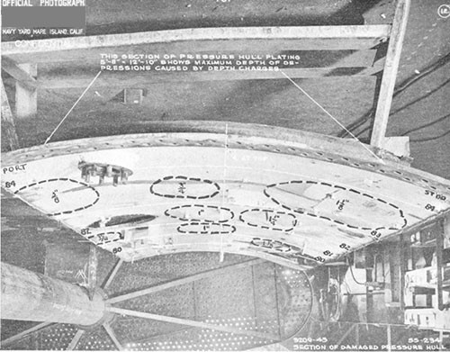
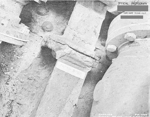
--39--
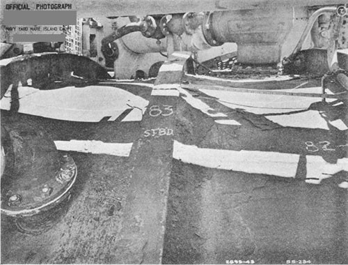
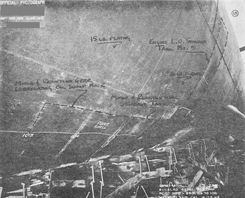
--40--
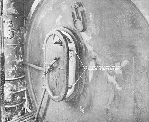
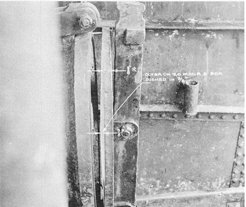
--41--
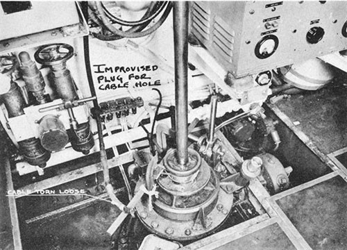
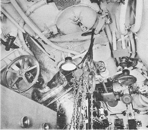
--42--
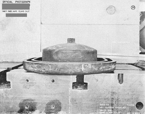
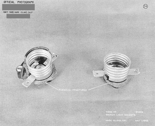
--43--
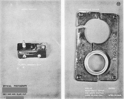
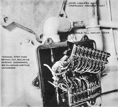
--44--
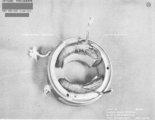
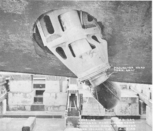
--45--
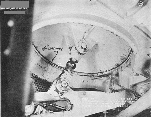
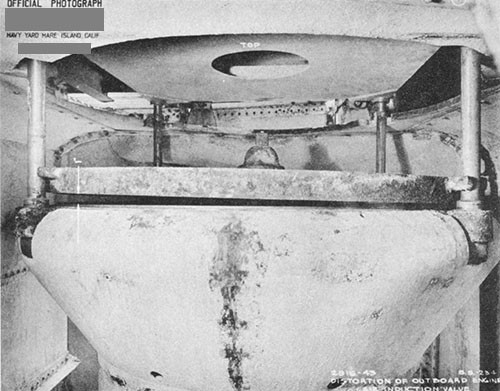
--46--
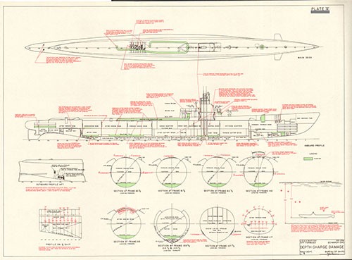
U.S.S. TUNNY (SS282)
Depth Charge Damage Forward
Off Palau Islands
26 August 1943
| Class | SS212 |
| Builder | U.S. Navy Yard, Mare Island |
| Commissioned | 1 September 1942 |
| Length (Overall) | 311 ft. 8 in. |
| Beam (Extreme) | 27 ft. 3-1/4 in. |
| Submergence Depth (Designed Maximum) (Axis) | 300 ft. |
| Displacements | |
| Standard | 1525 tons |
| Emergency Driving Trim | 1946 tons |
| Submerged | 2410 tons |
| Draft (Mean, Emergency Diving Trim) | 16 ft. 2 in. |
| Type of Propulsion | Diesel Electric Reduction Drive |
| Main Engines (4) | Fairbanks-Morse 38-D-8-1/8 |
| Main Motors (4) and Generators (4) | General Electric Co. |
References:
(a) C.O. TUNNY conf. ltr. SS282/A16-3/A9, Serial No. C-16 of 8 September 1943 (Report of War Patrol Number Four).
(b) C.O. TUNNY conf. ltr. SS282/S9, Serial No. C-18 of 15 September 1943 (Report of War Damage).
(c) OinC U.S. Naval Drydocks, Hunter's Point conf. ltr. SS282/L11-1 (06566); (308) of 8 March 1944 (Supplementary Report on TUNNY War Damage).
Photographs Nos. 6-1 through 6-7 (furnished by C.O. TUNNY, Naval Drydocks, Hunter's Point, and Bureau of Ships)
PLATE VI
6-1. On 26 August 1943, during her fourth war patrol, TUNNY underwent a severe depth charge attack off the Palau Islands. Two charges detonated close aboard the bow while the ship was submerged to a depth of 300 feet, causing extensive structural damage to the single hull plating and framing in way of the forward torpedo room and considerable other damage throughout the boat. Although depth control was temporarily lost, due to jammed bow planes and brief cutoff of main power, TUNNY was able to remain submerged and make good her escape. This report is based on the information contained in the references and on informal interviews with various officers attached to TUNNY. The Photographs were furnished by C.O. TUNNY, U.S. Naval Drydocks, Hunter's Point, and this Bureau. The PLATE was prepared by the Bureau and the structural indentations noted thereon are based on data contained in the enclosures to reference (c).
6-2. TUNNY arrived at the Submarine Base, Pearl Harbor, on 14 July 1943 from her third war patrol. Following normal refit and training, she departed Pearl Harbor for Midway on 5 August and arrived on 9 August. Here minor voyage repairs were made and fuel and lubricating oil were topped off. On 10 August TUNNY departed Midway for her fourth war patrol and on 22 August reached her assigned patrol area in the waters adjacent to the Palau Islands.
6-3. On 25 August TUNNY damaged two medium-sized freighters out of a six-ship Japanese convoy by one torpedo hit each during a pre-dawn submerged attack. Further attacks against this convoy were terminated when TUNNY was forced to take evasive action by an enemy destroyer escort. After the escort had retired and the safety of darkness permitted, TUNNY surfaced and remained on the surface until near dawn on 26 August, submerging again at 0412.
6-4. At 0959, 26 August 1943, while still submerged, periscope contact was established with two medium-sized Japanese freighters approaching from the south, escorted by one aircraft (DAVE) and one PC type surface vessel. TUNNY was at this time in a position off Toagel Mlungui Pass about 3,000 yards outside the reef to westward of Babelthuap Island, lat. 7° 30' N., long. 134° 20' E. At 1037, after closing to make a submerged periscope attack and with the enemy PC only 400 yards off her starboard beam, TUNNY fired a spread of three torpedoes at the leading freighter from a range of 980 yards and two torpedoes at the second freighter from a range of 1260 yards. As the last torpedo was fired, TUNNY headed for 300 foot depth at full speed, rigged ship for silent running and depth charge attack, and commenced evasive action. On the way down, two hits on the first freighter were heard. The propellers of this ship stopped and were not heard again. The second freighter turned toward TUNNY, successfully avoiding both torpedoes, and passed directly overhead.
6-5. At 1058, 20 minutes after the attack, either the enemy PC or DAVE located TUNNY and dropped two depth charges or depth bombs. These detonated well above the ship and did no damage. Two minutes
later, at 1100, six depth charges were dropped by the PC in close pattern around TUNNY and in rapid succession, detonating a few seconds apart. The first two charges detonated fairly close over the after portion of the ship but caused no damage, with the possible exception of that which occurred to the control cubicle in the maneuvering room. The second two charges detonated amidships above the conning tower and, although closer, caused no structural damage and probably little, if any, shock damage. The last two charges detonated close to the bow, causing extensive structural deformation forward and considerable damage to fittings and equipment throughout the boat. After this attack, no more depth charges were dropped, although the enemy vessel remained in TUNNY's immediate vicinity for several hours.
6-6. From the location and degree of deformation which occurred to the forward pressure hull structure, it appears that the last two depth charges detonated port and starboard abreast the forward trim tank at or just below the level of the pressure hull axis. All six charges were probably of the Japanese Type 95, Mod. 2 design, containing 242 pounds Type 1 explosive, and were probably set by pairs for detonation at 98, 197 and 292 feet. Since TUNNY was submerged to a depth of 300 feet, the setting of 292 feet, which was the maximum setting possible with the Type 95 depth charge pistol, would have resulted in detonation at the proper depth to correspond with the damage which actually did occur. Based on known behavior of similar type structures when subjected to underwater explosions, it is estimated that both charges detonated about 50 feet from the hull.
6-7. The depth charge attack had immediate serious effects on TUNNY, (a) Personnel forward were thrown from their feet and loose gear was hurled about, (b) Propulsion power was temporarily cut off by ship's force due to a fire in the main control cubicle which started when the positive and negative main battery busses jarred together momentarily, (c) Shortly afterwards, auxiliary power was also lost throughout the boat for several minutes when the auxiliary circuit breaker aft opened. The exact reason for this casualty is not known, but was reported by the Commanding Officer to have been due to maloperation of the auxiliary switchboard by personnel rather than material failure due to depth charging. This naturally added somewhat to the tendency for confusion which exists after any severe attack, (d) The bow planes jammed on 9 degrees dive angle due to misalignment and binding in the operating gear caused by distortion of supporting structure, (e) The upward water thrust from the depth charge detonations under the bow and the downward thrust from the detonations over the stern immediately caused the ship to assume a 20 degree up angle. Men were sent forward quickly in an effort to reduce this angle. The ship climbed to 200 feet but the angle on the boat then reversed, due to the bow planes being jammed in dive position and the added weight of the men sent forward. The ascent was followed by a steep glide to about 380 feet. Depth control was finally regained several minutes later, after much porpoising, by shifting from hand to power operation of the stern planes when auxiliary power again became available. The bow planes were then forced back to 5 degrees dive angle by using emergency hydraulic power; i.e., taking oil directly from the main hydraulic plant. However, the planes could not be tilted below 5 degrees by either hand or power operation. The damage control parties functioned coolly and efficiently throughout this period, restoring order and almost normal conditions within five minutes after the attack.
6-8. That TUNNY neither broached nor went excessively deep after depth control was lost was attributed by the Commanding Officer in large measure to the fact that the boat was fortunately operating at this time in a pronounced negative temperature gradient. This caused the boat to become heavy overall as it ascended and light overall as it descended.1 The effect was sufficient to keep TUNNY oscillating within the water strata below 200 foot depth and above 380 foot depth.
6-9. After regaining propulsion power, TUNNY retired to the southwest at two-thirds speed, running at 360 foot depth and under the sonar protection of the temperature gradient. The enemy PC passed overhead once more but did not attack, either having no depth charges left or not detecting TUNNY's presence. At 1625, TUNNY commenced operating at periscope depth and secured from silent running. At 1858 she surfaced and proceeded to clear the area rapidly.
6-10. At this time it was felt that perhaps sufficient repairs could be effected to enable TUNNY to remain on patrol. Inspection of the topside revealed that the bow had received considerable damage. Numerous pieces of torn and twisted metal from the cases of the depth charges, about 15 pounds in all, were found scattered over the superstructure deck forward of the capstan. The bow buoyancy tank vent valve operating gear had jammed with the forward vent in closed position and the after vent only partially opened. In order that the boat might again dive, a permanent vent opening was made in the bow buoyancy tank top by removing the manhole access plate. By slacking off on the bow plane tilting shaft packing glands and applying liberal amounts of grease to the bushings, the planes were finally jacked back to zero tilt from within the boat and rigged in.2 Work was started at once on the stern torpedo tubes, where it was discovered that all four gyro spindles had been bent and could not be withdrawn. All hands were kept busy restoring order and attempting repairs to deranged equipment.
6-11. By midnight of 28 August, everything within the power of the ship's force to put the ship in normal operating condition had been accomplished, but the following unsatisfactory conditions remained:
(a) Bow planes still could not be tilted either in hand or power operation, making depth control near the surface somewhat erratic.
____________
1 For each degree F. change in sea water temperature in the vicinity of 70° F., assuming average salinity content and near surface conditions, the change in buoyancy of an SS212 Class will be of the order of 825 pounds.
2 A modification to permit rigging bow planes over a wide tilt angle range of from 0° to 15° dive was authorized for SS198 and subsequent submarines by BuShips ltr. SS/S22(515-815) of 24 November 1944. Had this alteration been accomplished on TUNNY at this time, the bow planes could have been rigged in immediately, even though jammed on 5° dive.
(b) Bow buoyancy tank was unusable as such.
(c) Considerable air leakage through the 600-pound blow manifold for the forward group of main ballast tanks made it necessary to secure the individual tank hull regulator stop valves when submerged (this condition was present before depth charging).
(d) No. 2 low pressure blower was out of commission due to a short-circuited shunt field.
(e) The optics of No. 2 periscope were deranged, reducing light transmission by 25 per cent.
(f) The IMC system on the bridge and in the conning tower was irreparably damaged.
(g) Two of the remaining eight torpedoes required a major overhaul.
(h) All forward torpedo tubes were out of line and out of round, preventing firing of torpedoes from these tubes.
(i) The JK-QC sound projector could not be trained.
6-12. Since the above conditions rendered TUNNY's offensive power negligible, it was decided to return to base for repairs and make her very active area available to another submarine. Therefore, at 0013 on 29 August, TUNNY departed for Pearl Harbor. The return trip was made entirely on the surface except for occasional dives when enemy or unidentified aircraft were sighted. Diving time without the aid of the bow planes was 60 to 75 seconds, somewhat slower than the normal time of about 45 seconds. TUNNY arrived at Submarine Base, Pearl Harbor on 8 September.
6-13. Structural damage was confined to the ship forward of frame 31. Damage to the elliptically shaped single pressure hull in this region consisted of minor distortion of the framing with marked general depressions of the shell plating between frames (PLATE VI, Photos 6-1 through 6-5). Transverse bulkheads at frames 10, 13 and 16 were slightly buckled. Bow buoyancy tank frames and plating were dished inward (Photo 6-6) and the superstructure deck plating was slightly buckled. Examination of the vessel revealed that the entire forward section had been displaced to starboard. This deflection increased from 1/8 inch at frame 37 (forward knuckle) to 1 inch at the bullnose. There was local bending of the stem bar to port between frames A and B, the maximum displacement amounting to about 2 inches at the 20-foot waterline (Photo 6-6). The bullnose was found to have moved upward 1/2 inch relative to the base line.
6-14. Deformation of the pressure hull plating was about equally distributed port and starboard (Photos 6-1 and 6-4). The maximum plating indentation on the starboard side was 2-1/16 inches in way of the forward trim tank between frames 13 and 14 at about the 14-foot waterline. General dishing of plating on the starboard side extended aft to frame 25 and was
concentrated between the 10-foot and 14-foot waterlines, depths of indentation averaging between 1 and 1-1/2 inches. Damage to the port side pressure hull plating was similar to the starboard side in nature and location, although it did not include as large an area. Minor isolated dents, not shown on PLATE VI, occurred both port and starboard.
6-15. The bossing for the bow plane tilting shaft sector gear, built into the overhead of the pressure hull between frames 16 and 17, was depressed both port and starboard to a depth of about 2 inches (Photo 6-5). Since no other pressure hull plating in this vicinity was affected, it was apparent that a structural weakness existed in the design of the bossed area. Another region of local failure was the section of the hull plating between the escape trunk and the torpedo loading hatch, which was depressed to a depth of about 1 inch over a distance of about four feet on either side of the centerline. However, no difficulty was encountered in removing the transverse compression strut in the torpedo loading hatch after the damage, demonstrating that the hull distortion was not sufficient to jam the strut threads.
6-16. All welded seams and butts in the pressure hull remained tight, even though some were severely distorted. Welds joining framing to plating were also undamaged. There was no leakage into the boat which could be attributed to depth charge damage.
6-17. Pressure hull frames 13 to 30 were found to deviate slightly from their designed offsets, maximum variation occurring in way of the forward trim tank and forward portion of the torpedo room. Considered as a whole, the starboard framing presented a fair surface although actually deflected outboard by amounts from as high as 3/4 inch to an average of only 1/4 inch. Maximum deflections occurred in the vicinity of the 5-foot waterline. There were no local depressions in any frames. Portside framing was, in general, pushed inboard, but deflections were less than on the starboard side. There was, however, some unfairness of framing. Maximum frame deformations on the port side occurred in the vicinity of the 13-foot waterline but varied from designed offsets by only 1/8 to 1/4 inch. These latter variations are insignificant and may well have occurred during construction of the vessel. PLATE VI illustrates the relative distortion of the pressure hull ellipse from the designed dimensions.
6-18. Bulkhead 10, the after bulkhead of the bow buoyancy tank, sustained only minor distortion but this was sufficient to jam the operating shaft for the bow buoyancy vent valves. Bulkhead 13, the forward bulkhead of the forward trim tank, was generally depressed aft between the torpedo tubes and the shell, port and starboard, with a maximum deflection of about 3/4 inch. This bulkhead leaked slightly around the tubes, allowing a small amount of water to enter the trim tank when submerged. Bulkhead 16, the after bulkhead of the forward trim tank, sustained only minor distortion but did move slightly relative to the torpedo tubes. This was evidenced by bright metal showing on the
tube collar shoulders, but the motion was not sufficient to shear the flat head screws securing the bulkhead collars to the tubes nor did any leakage into the boat occur.
6-19. Superstructure and bow buoyancy tank damage was minor. The side plating of the bow buoyancy tank was depressed between frames forward of frame 0, principally on the starboard side (Photo 6-6). The rolled deck gunwale plates, both port and starboard, were severely buckled between frames 17 and 18, indicating that the bow had been whipped upwards by one of the close detonations, putting the deck in compression in the region of the buckles. The deck plating forming the top of the bow buoyancy tank was cracked in one place only. This occurred as a result of a stiffener on bulkhead 10 pulling away from the underside of the deck.
6-20. One of the most serious results of the depth charge attack was the damage which disabled the bow plane tilting gear. The principal cause of this derangement was binding due to misalignment of the main herringbone pinion and the sector gear on the bow plane shaft, caused by the deflection of the forward trim tank bulkhead at frame 16 upon which this gear assembly was mounted. Secondary binding of the tilting shaft also occurred port and starboard at the pressure hull stuffing boxes and was caused by distortion of the elliptical hull. The bow plane rigging mechanism remained completely operable, although some misalignment of the transmission shafting was discovered afterwards when disassembling the equipment.
6-21. The only casualty which occurred to the main propulsion plant and associated systems and auxiliaries was the control cubicle derangement previously mentioned. Although the control cubicle was not shock-mounted, it withstood impact without damage to contactor groups or mechanical equipment. However, the positive and negative main battery busses in the forward contactor cell were momentarily thrown together, causing a small fire and considerable pitting of the busses (Photo 6-7).1 Simultaneously, the battery selector lever jumped from the "Both Batteries" position to the "Forward Battery" position. The main motors were stopped for about one or two minutes to extinguish the fire and then were started again on the forward battery only. Damage resulting from the fire was negligible, but dense toxic smoke given off by burning glyptol insulating varnish on the bus bars made inspection of the cubicle difficult and forced several men to abandon the maneuvering room.
6-22. The lighting systems were not appreciably damaged, with the exception of numerous broken bulbs and a resistor in the forward engine room emergency lighting circuit which short-circuited and caused a full voltage ground across the forward battery. Since the boat was rigged for silent running, only the emergency lighting system was on at the time
____________
1 As a result of this casualty, the installation of phenolic insulation between the propulsion control cubicle main battery busses to prevent short-circuiting under shock was authorized by ShipAlt SS222 of 6 December 1943 for TUNNY and all other applicable submarines.
of the attack. Numerous gauges and meters were thrown out of calibration and a few sustained damage. Several thermometers in the engine rooms were broken. The shock effect was widespread throughout the boat and there was no apparent concentration in any one locality.
6-23. During the attack mercury spilled from the float chambers of both the master and auxiliary gyro compasses, putting them out of commission and necessitating dismantling for cleaning and readjustment. The glass cover of the gyro repeater on the bridge was broken and the instrument flooded. After the casualty occurred to the gyro compasses, the ship was steered by magnetic compass. The fact that the battery selector lever in the control stand had moved from the "Both Batteries" position to the "Forward Battery" was not discovered until about ten minutes after the attack occurred when it was noted that both magnetic compasses (tank type and boat) were behaving erratically. This was due to the fact that the compasses had been compensated a few days previously for the magnetic conditions present with the ship taking propulsion power from both the forward and after batteries. Drawing power from only the forward battery set up an unbalanced magnetic field of sufficient intensity to produce a deviation of as much as 30°.
6-24. The upper prisms of both periscopes were cracked. The power field of No. 2 periscope was out of focus and light transmission reduced by 25 per cent. Nitrogen pressure was lost in No. 2 periscope but the periscope was recharged to eight pounds.
6-25. There was only one major piping leak which developed as a result of the attack. This occurred at the high pressure air (3000-pound) receiving and distribution manifolds in the control room and caused great concern to all hands. The manifold assembly was installed in such a manner that it was supported principally by the piping leading to it, permitting large deflections under impact. The cone joint at the connection of the after high pressure air riser to the distribution manifold opened sufficiently to permit serious leakage but fortunately did not carry away completely.1 Air pressure within the boat increased appreciably but the amount could not be measured since all barometers and manometers were damaged. Although there was considerable structural damage in way of the forward torpedo air impulse flasks, located outside the pressure hull, the flanged joints of the impulse piping both at the flasks and pressure hull remained tight and the banks did not bleed down. As previously mentioned, a valve leak in the 600-pound blow manifold supplying the lines leading to the forward group of ballast tanks necessitated securing the individual tank hull stop valves to prevent air from forming bubbles in those tanks. This leak was present before the attack but was aggravated by the depth charge detonations. Hydraulic lines and fittings generally remained tight
____________
1 As a result of this casualty on TUNNY, and the similar experience of KINGFISH (SS234) on 23 March 1943, ComSubPac conf. ltr. FF12-10/S49/L11-1/70 of 20 November 1943 directed that the high pressure air receiving and distribution manifolds be rigidly bracketed together and to the hull on all submarines where existing support was not sufficiently rigid. NYMI Plan No. 65557 was developed as a typical bracketing arrangement.
except for several serious leaks in the control room. Numerous valves throughout the ship, regardless of location, partially opened under impact, the discs backing off the seats. Both the forward and after 225-pound service air lines had to be secured at the manifold until damage control personnel could check and reclose the valves in that system. For example, the 225-pound air valve to the conning tower1 opened on each of several close detonations and was closed on each occasion by the Commanding Officer himself. Trim line strainers were partially clogged in the variable tanks when depth charging caused flaking of the plastic composition with which those tanks were coated.2 All vent and flood valves were undamaged with the exception of the bow buoyancy vent valves, previously mentioned.
6-26. Both the SD and SJ radars were deranged by the impact of the depth charges, the SJ becoming inoperable. On the SJ, the cathode ray tube was damaged internally so that the registered sweep was only 2 inches wide, the magnetron tube failed, the triode tube jarred out of its socket and the bearing indicator slipped 10 degrees out of phase. The SD radar withstood the impact somewhat better. It could be made to pulse but was also badly out of adjustment and it was found necessary to renew thirteen tubes shortly after the attack, indicating that they were considerably affected by the impact. No damage to radio equipment occurred. There was no damage to the electronic portion of the sonar equipment but the drift stops on the port JK-QC sound projector crushed under impact, preventing it from training, and the starboard QB head was slightly dented. Both heads were operable electronically after the attack.
6-27. All forward torpedo tubes were found to be both out of line and out of round. The deviation in alignment was fairly uniform and was apparently due only to the displacement of the entire bow structure to starboard. The azimuth error varied from 13 minutes starboard on tube No. 1 to 15 minutes starboard on tube No. 6. In addition, all forward tubes were slightly bent along their longitudinal axis, the maximum deviation being 0.110 inches on tube No. 5. The bending occurred at the junction of the breech section of the tubes with the middle section, at the forward trim tank bulkhead. The monel screws securing these sections apparently loosened somewhat, for it was reported that the sealing compound around the screws backed out and slight leakage occurred into the tubes. The circular distortion of the tubes was such that it was found impossible to start a bore gauge in any of them, tube No. 6 being out of round by as much as .210 inches. The outer doors, shatters and operating gear on all tubes remained workable in spite of
____________
1 The 225-pound blow line to conning towers was later removed on all submarines when that compartment was disestablished as an escape station.
2 Due to its tendency to flake, this white plastic composition, formula 89 (Barrierkote) was subsequently removed from all submarine variable tanks and replaced with rust preventative compound (N.D. Spec. 52C18, Grade III).
the distortion to the intervening bulkheads. Tubes Nos. 1 and 4 were reported by reference (a) to have flooded as a result of the attack, the muzzle door gaskets presumably sustaining some damage. No misalignment or distortion occurred to the after tube nest. However, the after tubes were loaded and flooded at the time of the attack and movement of the torpedoes under impact within the tubes bent the gyro setting spindles and guide sleeves so that the spindles could not be withdrawn. All torpedoes were removed for checking and the spindle assemblies were replaced by the ship's force, using the one available spare and three taken from forward tubes. The stop bolt in No. 10 torpedo tube was also found to have been bent and this was replaced. Two torpedoes were so shaken up internally that they required a major overhaul beyond the capacity of ship's force. The other six were thoroughly checked and considered satisfactory.
6-28. Upon arrival at the Submarine Base, Pearl Harbor, TUNNY was immediately docked in the ARD-1 to investigate the extent of structural damage. She departed Pearl Harbor on 11 September 1943 and arrived at U.S. Naval Drydocks, Hunter's Point, on 17 September. Complete damage repairs, regular overhaul and the majority of the outstanding alterations were accomplished there. The entire forward torpedo tube nest was removed from the ship and repairs were made to the individual tubes prior to reinstallation. Renewal of the forward pressure hull structure was accomplished as indicated by the outlines on PLATE VI. TUNNY was returned to active service on 2 January 1944.
6-29. As a matter of interest, TUNNY was twice more seriously damaged by bomb attack on subsequent patrols, the first action occurring on 30 March 1944 during her fifth patrol and the second action occurring on 1 September 1944 during her seventh patrol.1 On both occasions the bombs detonated in close proximity to the maneuvering room. In the first instance, control cubicle damage was again sustained although the cubicle was shock-mounted during the overhaul completed just prior to the patrol. It is understood, however, that later examination disclosed that one of the cubicle transverse support frames was improperly placed so that it was in direct contact with the cubicle cage, thus nullifying the effect of the rubber mounting. This condition was corrected and it is significant to note that although in the subsequent action of 1 September 1944 the bomb detonated close enough to permanently deform several areas of the pressure hull in way of the maneuvering room, no damage was sustained by the control cubicle.
____________
1 See briefs of damage in Appendix I for these two subsequent actions.
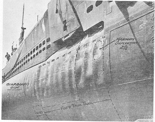
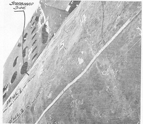
--57--
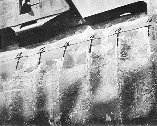
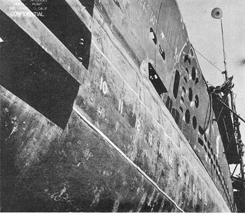
--58--
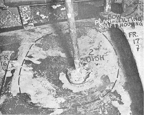
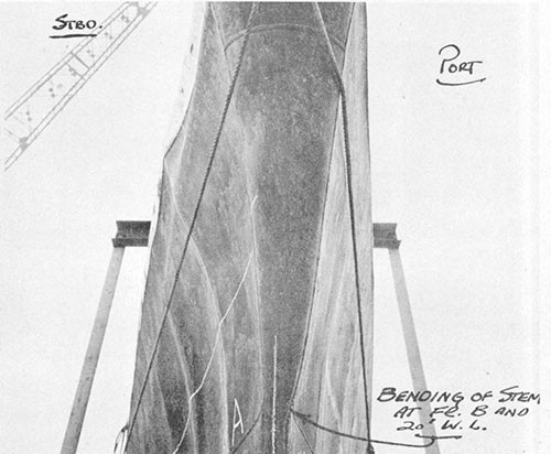
--59--
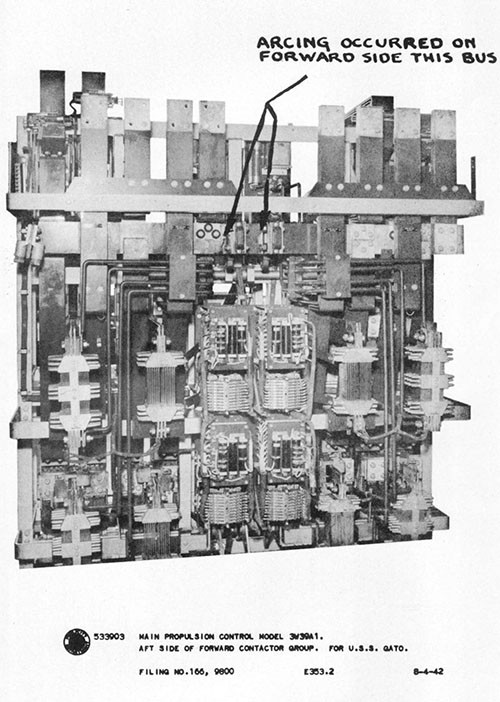
--60--
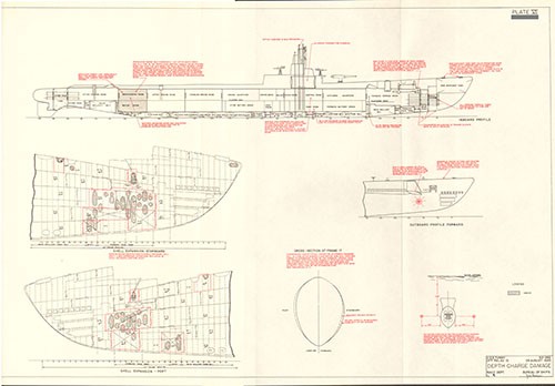
U.S.S. SALMON (SS182)
Depth Charge Damage
Southeast of Kyushu
30 October 1944
| Class | SS182 |
| Builder | Electric Boat Co., Groton, Conn. |
| Commissioned | 15 March 1938 |
| Length (Overall) | 308 ft. 0 in. |
| Beam (Extreme) | 26 ft. 2 in. |
| Submergence Depth (Designed Maximum)(Axis) | 250 ft. |
| Displacements | |
| Standard | 1435 tons |
| Emergency Diving Trim | 1885 tons |
| Submerged | 2210 tons |
| Draft (Mean, Emergency Diving Trim) | 17 ft. 6 in. |
| Type of Propulsion | Composite |
| Main Engines (4) | General Motors 16-278A |
| Main Motors (4) and Generators (2) | Elliott Co. |
References:
(a) C.O. SALMON conf. ltr. SS182/A9/A-16-3, Serial No. 0-16 of 10 November 1944 (Report of War Patrol Number Eleven).
(b) C.O. SALMON conf. ltr. SS182/A9-8, Serial No. 024 of 11 December 1944 (War Damage Report).
(c) OinC U. S. Naval Drydocks, Hunter's Point conf. ltr. SS182/L11-1(012459)(308) of 29 March 1944 (Supplementary War Damage Report).
(d) U.S. Navy Board of Inspection and Survey ltr. SS182/S3-1 (5000-S), Serial No. 271121 of 18 December 1944.
Photographs Nos. 7-1 through 7-13 (furnished by Naval Drydocks, Hunter's Point).
PLATE VII
7-1. On 30 October 1944 during her eleventh war patrol, SALMON underwent a severe depth charge attack southeast of Kyushu while submerged at a depth of about 300 feet. As a result of this attack, SALMON incurred severe damage. This case of damage can be considered one of the most serious to have been survived by any U.S. submarine during World War II. Pressure hull deformation was extensive in way of both engine rooms. The external main engine air induction piping collapsed and flooded, causing the ship to become heavy overall, and the stern diving planes jammed in "full dive" position. Depth control was immediately lost and SALMON oscillated up and down several times, remaining submerged only by blowing the safety tank and by going ahead at emergency speed with a 20 degree up angle on the boat. Seventeen minutes after the attack, with batteries depleted, the after engine room flooded almost to the level of the main motors, and still not having achieved depth control, SALMON surfaced, outgunned the opposing Japanese escorts and escaped with three engines on full power. This report is based on the information contained in the references and on further informal correspondence with the then Commanding Officer. The Photographs were furnished by Naval Drydocks, Hunter's Point. The PLATE was prepared by this Bureau.
7-2. Upon completion of her tenth war patrol, SALMON underwent an extensive overhaul at Navy Yard, Mare Island. During this period the four Hoover, Owens and Renschler main Diesel engines were replaced by General Motors Model 16-278A engines and all of a long list of important outstanding alterations were accomplished.
7-3. SALMON completed overhaul and departed from Navy Yard, Mare Island for the Submarine Base, Pearl Harbor on 4 September 1944, arriving on 12 September. From 12 September to 17 September, voyage repairs were made at the Submarine Base and from 17 September to 21 September training exercises were conducted in the Hawaiian area. SALMON departed from Pearl Harbor on 24 September and arrived in Tanapag Harbor, Saipan, on 3 October. There minor voyage repairs were again made and fuel and lubricating oil were topped off.
7-4. SALMON departed Saipan on 4 October for her eleventh war patrol in company with SILVERSIDES (SS236) and TRIGGER (SS237), forming a coordinated attack group. Her assigned patrol area was along the eastern boundary of the Nansei Shoto Islands on the southern approaches to the Japanese home islands. Although independent searches were conducted over a wide area by the group, and numerous harbors were reconnoitered, no suitable targets were sighted until 30 October.
7-5. At 0401 on 30 October 1944, SALMON established radar contact with a large Japanese tanker escorted by four frigate class vessels, radioed a contact report giving the position, course and speed of the target, and then commenced surface chase. Chase was long and difficult
due to the high speed of the tanker, its radical course changes, and occasional rain squalls during which contact was lost for short periods. At 1620, SALMON noted a large explosion in the target's stern (result of TRIGGER attack) and the tanker appeared to stop shortly afterwards. Anti-submarine activity by the escorts started at once and many depth charge explosions were heard through the hull during the next half hour.
7-6. At 1740, SALMON started closing the range for an attack. The enemy tanker was at this time immobilized about 24,000 yards distant, bearing 170° (T) and drifting with the wind in a southwesterly direction at a speed of about one and one-half knots. The four Japanese escorts were patrolling slowly back and forth about 1200 yards on both sides of the tanker. SALMON'S position was lat. 30° 08' N., long. 132° 33' E., about 120 miles southeast of Kyushu. The sea was moderate and the wind was Beaufort force 3 to 4. At 1823, upon closing the range to about 8000 yards, SALMON submerged and commenced attack approach. Her main shafts were squealing badly, a condition which had developed during the preceding few days and was steadily getting worse. At 2001, at an estimated range to the target of 3,300 yards, a spread of four torpedoes was fired, two of which struck and detonated in the target.1
7-7. At the time of firing, SALMON was on course 215 degrees and at periscope depth of 64 feet. The long firing range was accepted because three of the enemy escorts were approaching rapidly and it was feared that no further decrease in range could be made without detection. Immediately after firing, SALMON swung right, using full rudder, in order to bring her stern tubes to bear for another salvo should it become necessary. However, three of the four torpedoes of the initial salvo were seen to broach and either this evidence of SALMON'S presence or positive detection by sonar caused two of the escorts to head directly toward her almost simultaneously from each quarter so, at 2012, SALMON went deep. As the boat submerged, speed was increased to standard and the rudder was put in full left position. One minute later, at 2013, when a depth of 310 feet had been reached, a series of small "sono-bomb" explosions were heard.2 These were followed almost immediately by the first of four close and well delivered depth charge patterns.
____________
1 Although TRIGGER (SS237) and SALMON each made torpedo hits on this tanker, it remained afloat and was later sunk by STERLET (SS392). SALMON was officially credited with a "sunk" tonnage of 3,300 tons, equal to one-third the total estimated tonnage of the tamper.
2 These "sono-bomb" explosions may have been either "Emit Sound Missiles", known to have been frequently used by the Japanese just prior to commencing a depth charge attack, or the detonations of projector charges in depth charge throwers on the escorts (See paragraph 3-19).
7-8. A total of about thirty depth charges were dropped, each of the four separate patterns consisting of from six to eight charges. The first and second patterns were received almost simultaneously and one or more of these charges detonated very close aboard over the engine rooms, causing the collapse and flooding of the engine air induction piping and possibly some or all of the pressure hull deformation between the tank tops over the engine rooms. The final two patterns followed a short time later but were not close enough to have serious effects although the boat was shaken up considerably. All of the thirty or so depth charges detonated aft in so far as could be determined on SALMON. The Commanding Officer reported that severe flexural vibrations of the ship as a whole occurred during close detonations, stating that "The conning tower vibrated up and down so violently that I thought the ship was going to shake herself apart. I remember bending my knees to ease the shock". Damage to the ship was severe and widespread. Unattached gear and many inadequately secured small fixtures were hurled about during close detonations and presented an appreciable missile hazard to personnel in some areas.
7-9. The most serious immediate effect of the attack was that depth control was lost. The boat became heavy overall and started to settle rapidly. Several factors contributed to this dangerous situation: (a) loss of buoyancy due to collapse and flooding of the external main engine air induction piping; (b) added weight due to flooding of three deck access hatch trunks, profuse leakage of sea water into the interior of the hull at various points and the displacement of about 7,000 gallons of fuel oil in FBT No. 7 with heavier sea water through the ruptured vent riser of that tank; (c) jamming of the stern planes in "hard dive" position due to binding of the stern plane hand tilting shafting in the after engine room by a local indentation of the pressure hull and shattering of the stern plane drive shaft coupling in the after torpedo room; and (d) the downward flow of water from the overhead depth charge detonations.
7-10. Submerged propulsion power was unaffected and was a vital factor in the survival of the boat. Auxiliary power forward was temporarily lost when shock caused the auxiliary power circuit breaker in the after engine room to trip. However, the breaker was reset by hand shortly after it opened and auxiliary power was restored throughout the boat. No. 1 lighting motor generator voltage regulator control was damaged and, since this generator was supplying the standard lighting load, all ship's service lighting failed and the ship was plunged in darkness. The emergency lighting system was switched on immediately, however, and operated satisfactorily although numerous light bulbs throughout the boat were broken. Various IC and auxiliary motor controller panel contactors opened under shock and had to be reset by hand.
7-11. Only one serious air system leak developed, this occurring in the forward engine room at a joint in No. 1 main engine air starting line (500-pound). Numerous minor air leaks developed throughout the boat. Power steering control was lost due to disconnection by shock of the supply piping to the steering hydraulic manifold in the after torpedo room. Steering control was not regained until about five minutes later when a shift was made to hand operation.
7-12. The most serious leakage into the hull was that which occurred in both engine rooms through the fuel ballast tank riser inboard vent lines, the stop valves having torn from their holding studs. The sea water streams resulting at these points were small in cross section but fast, and rapidly filled the bilges. The drain line suction strainers in the engine rooms were clogged with debris rendering it impossible to pump the water flooding into those two compartments. The water level eventually neared the main motors and was one of several reasons which soon forced SALMON to surface. Serious leakage also occurred in the conning tower as described in paragraphs 7-23 and 7-25.
7-13. When it was first noticed that SALMON was increasing depth rapidly, emergency speed ahead was rung up, a 20 degree up angle was set on the boat with the bow planes and the auxiliary tanks were pumped. These measures served to check the descent at about 400 feet depth. The boat then rose to about 300 feet but when an attempt was made to level off and reduce speed to standard, SALMON again settled rapidly. Emergency speed ahead and a 20 degree up angle on the boat were once again resorted to and in addition the safety tank was blown, but this time the descent was not halted until a depth of about 500 feet had been reached. Once more the boat started to rise and reached 150 feet depth but started to drop again when another attempt was made to level off. This time SALMON went quite quickly to about 500 feet depth, in spite of again using emergency speed ahead and a 20 degree up angle, and then gradually settled to a reported 578 feet depth. The situation at this time was as follows: the main batteries were considerably depleted from sustained high speeds submerged; depth control still had not been restored and was getting more difficult rather than easier; the water level in the after engine room was rising and had reached the main motor casings; and pump suction could not be obtained aft to correct trim due to the clogged bilge strainers. As the depth was apparently already 578 feet and slowly increasing, the Commanding Officer decided that the only chance of survival for the ship lay in surfacing at once and attempting to fight off the enemy escorts. Therefore, at 2030, seventeen minutes after first being attacked, SALMON started to blow tanks for a battle surface.
7-14. SALMON twice reached depths greater than the maximum indication of her 450 foot depth gauge and on each of these occasions depth readings were thereafter obtained from a control room sea pressure gauge calibrated in pounds per square inch. This method of determining depth was of course only as reliable as the gauge itself. No information is available as to whether this particular gauge was later checked for accuracy of calibration. However, it is known that numerous other pressure gauges, meters and instruments were deranged by shock. It should be noted that since the maximum depth apparently reached, 578 feet, was measured at the control room, the approximate 20 degree up angle on the boat at that time still further increased the submergence at the after end of the pressure hull, resulting in a depth of slightly more than 600 feet at the after bulkhead of the after torpedo room. This
depth is greater than that at which collapse of the pressure hull would be expected to occur. Although astounding, it cannot be said to be impossible because there is considerable variation in the strength of submarines by reason of variations in the yield strength of the steel used in construction, which varies from heat to heat, and in the thickness of the steel which, by specification tolerances, is not and cannot be required to be exactly the nominal thickness.
7-15. The fact that the stern planes were jammed in full dive position during SALMON'S inadvertent submerged gyrations was a help rather than a hindrance. This was because the boat became heavy overall and heavy aft and the stern planes offered a moderate amount of support tending to hold the stern up. The action of the stern planes on full dive was also beneficial in that it initially permitted some control over the attitude of the boat by use of the bow planes so as to maintain a reasonable up angle in order that the hull itself could be utilized as a plane to counteract the effect of being heavy overall. Later, as additional water entered the engine rooms and caused the boat to become progressively heavier aft, the smallest up angle which could be kept on the boat at emergency speed ahead was approximately 20 degrees even though the bow planes were placed in full dive position. It should be noted that had the stern planes been jammed in hard rise position, the effect of the planes together with the boat being heavy aft would have resulted in such a large up angle that SALMON would have been forced to surface almost immediately.
7-16. Although structural deformation was extensive, particularly in way of the forward and after engine rooms, in no place were the pressure hull or pressure tanks ruptured or torn and watertight integrity remained intact except for the profuse leakage which occurred at various pressure fittings. From the nature of the deformation of the pressure hull over the engine rooms and the fact that SALMON far exceeded its test depth, particularly aft by reason of the up angle while at great depth, it is believed that there is considerable probability that the pressure hull damage was caused by excessive submergence depth rather than by the depth charge attack.
7-17. The pressure hull plating between tank tops was generally depressed between frames 95 and 170. The indentation lobes in this area were for the most part confined to the pressure hull plating between frames only and were discontinuous with lobes in the adjacent frame spaces. Pressure hull frames within the same area were in some cases slightly tilted or buckled (Photo 7-1). No frames tore free from the hull plating. The area of heaviest deformation was between frames 130 and 145, with a maximum pressure hull indentation of about two inches between frames 137 and 139 (Photos 7-2, 7-3 and 7-4). Some distortion also extended a short distance below the tank tops. Forward of frame 95 and aft of frame 170 no structural damage was apparent. The pressure hull plating of the after trim tank was considerably depressed between frames undoubtedly as a direct result of the excessive hydrostatic pressure to which the hull was subjected when SALMON reached a depth of about 620 feet in that area (Photo 7-5).
7-18. The topside main engine air induction piping leading to the engine rooms completely collapsed and flooded (Photos 7-6 and 7-7). This collapse action probably occurred in two distinct stages: (a) initial partial flattening of local areas of the induction piping by depth charge pressure alone and (b) subsequent complete and longitudinally progressive collapse by direct hydrostatic pressure acting against the weakened unsymmetrical areas caused by (a). Flooding of the induction system alone caused SALMON to be heavy overall by about 13,500 pounds.
7-19. In addition to the collapse of the main induction piping, much other damage was sustained by materiel located outside or attached to the pressure hull. Wood decking and steel framing of the superstructure deck in the area of pressure hull damage were distorted and broken up, requiring extensive renewals. The master vent valve for MBT No. 1 jammed in the open position and remained so until forced shut by hand from topside after surfacing. The master vent valves for MBT Nos. 2E, 2F, 2G and 2H also jammed open but were closed by use of much leverage on the hand wheels. Due to distortion of structure and displacement of vent riser piping, the master vent valves for safety tank and MBT Nos. 2A, 2C, 2E and 2G could not be completely closed, lacking seating by from one to two inches. The vent risers for FBT No. 7 and MBT Nos. 2C, 2E and 2G were ruptured. Over 7,000 gallons of fuel oil were lost from FBT No. 7 through the damaged riser and the displacement of this oil by heavier sea water caused an increase in weight aft of about 11,000 pounds. All starboard tank emergency vent valves leaked and operated with difficulty. The low pressure blow lines to FBT Nos. 7 and 9 were ruptured, the line to FBT No. 7 apparently having been pierced by a solid object (Photo 7-8).
7-20. The outboard mushroom valve for the main induction and ship's ventilation exhaust trunk in the conning tower fairwater at frame 85 was warped slightly, preventing complete seating. No. 1 main engine muffler was dished in considerably and the surrounding decking broken up. All main engine outboard double-seal conical type exhaust valves leaked. Safety tank flood valve jammed in the open position and could not be closed. The residual drain piping in MBT No. 2E ruptured inside the tank. The radio antenna trunk system and the four-inch ammunition ready service stowage case, both located in the conning tower fairwater, flooded completely. On the bridge, the target bearing transmitter pressure-proof binoculars cracked, partially flooding, and the transmitting selsyns were deranged. The bridge pressure-proof 7MC speaker forward also flooded. All radio and the APR antennae insulators fractured. The one and one-half inch thick glass in the bridge pressure-proof gyro repeater granulated. The four-inch deck gun sights cracked and flooded, although the gun itself fortunately remained completely operable. Both periscope
head staunching plates fractured and the tubes flooded. No other damage occurred topside.
7-21. Flooding occurred in the deck access trunks to the after battery room at frame 90, the forward engine room at frame 125 and the after torpedo room at frame 170. All three of these trunks fortunately had been provided with the secondary boiler-type hatches at the lower ends of the trunks as authorized by BuShips ltr. C-SS/S16-3(515-815) of 28 February 1944. The outer hatches for the after battery and forward engine room access trunks were structurally undamaged and remained seated. Leakage was due to gasket damage plus excessive hydrostatic pressure. These two trunks flooded completely but the secondary hatches held and prevented water from entering the pressure hull. The after torpedo room access trunk upper hatch was forced open by the depth charge explosions to about a 30 degree angle and consequently left the trunk wide open to the sea. Here again the secondary hatch at the lower end of the trunk held tight under full sea pressure and without question saved the boat. To eliminate such a hatch casualty as the above, the installation of emergency securing turn-buckles to prevent the upper hatches from opening momentarily more than about two inches during depth charging was authorized by BuShips dispatch of March 1944. The turnbuckles had been installed on all of SALMON'S access hatches but had not been rigged on those which were backed up by secondary hatches.
7-22. In the conning tower, damage due to depth charging caused severe leakage at depths below 200 feet through the stuffing boxes of both periscopes, the steering wheel shaft packing, and around the gasket of the upper hatch. Some leakage is also reported to have occurred through electrical cable stuffing glands at deep depths. The conning tower bilges overflowed, both periscope wells flooded and considerable water drained through the lower hatch to the control and pump rooms. The IMC announcing system was put out of commission and the station relays were inoperative. The motor controller switch for No. 1 periscope was dismounted and the light switch for the TDC was broken.
7-23. In the control room the damage was relatively minor. The TP-TR panel was dismounted and many indicator bulbs were broken. The main gyrocompass panel short-circuited. The starboard engine order telegraph and telephone ringing circuit junction boxes fractured and short-circuited. About one-half of the pressure gauges were jarred out of calibration. Gauges that were properly shock mounted were reported to have apparently been unharmed. The tank type magnetic compass lost all directivity. Many light bulbs were broken. The fathometer went out of commission due to shock. The 200-pound air valve to the whistle topside and depth gauge sea chest blow valves
jarred open. The 220-pound service air distribution manifold leaked at the piping connections.
7-24. In the pump room, damage was quite serious. Auxiliary power forward was lost temporarily when the breaker aft in the maneuvering spaces tripped open. The breaker was quickly reset, however. Water draining from the conning tower and the hull ventilation drain flooded the bilges to a waist-high depth at the after end (20 degrees up angle). The following pump room electrical equipment was flooded out: Nos. 1 and 2 high pressure air compressor motors, SD radar mast hoist motor, two circulating water pump motors for air conditioning, and the periscope lower limit switches. The overload relays on Nos. 1 and 2 low pressure blowers tripped and Nos. 2 and 3 I.C. motor generator regulators short-circuited. The stems of sea valves in the circulating water lines to the air conditioning and high pressure air compressors were bent between the bonnets and the valve discs. Various hydraulic system piping and fitting leaks throughout the boat made it necessary to secure the main hydraulic plant until the sources of leakage could be isolated or repaired. The hydraulic plant itself was undamaged. Apparently no misalignment of any auxiliary equipment due to shock occurred in the pump room. The trim and drain pumps continued to run although in some compartments bilge suction strainers became clogged with loose cork.
7-25. In the forward torpedo room, the bow plane rigging motor panel was deranged and upon surfacing the planes had to be rigged in by hand. The QC sound gear shaft was forced up despite the holding pins, and its hydraulic supply line was torn loose. The pitometer log was found to operate erratically. The diving alarm short circuited. The officers' watercloset discharge line ruptured inboard of the hull valve.
7-26. No damage occurred in the forward battery compartment with the possible exception of one battery cell. This cell may have been cracked, for reference (a) reports that it had a high ground reading and that the electrolyte level was not visible. No subsequent information on the cell is available.
7-27. In the after battery compartment damage was comparatively minor. In the crew's mess room both the ship's supply ventilation hull flapper valve and the No. 2 sanitary tank overboard vent valve leaked heavily. Sea water flooded out the electric ranges in the galley. The battery cells and strongbacks in this compartment were unaffected and the well was dry. Several light bulbs and one mirror were broken and an oxygen bottle was torn loose from its overhead stowage position.
7-28. In the forward engine room, the No. 1 main engine completely flooded through the exhaust piping system. The depth charging caused
the outboard exhaust valve to leak and jarred the inboard exhaust valve (gate) partially open. The No. 4 liner of this engine also fractured. The No. 1 engine air starting line ruptured, causing serious air leakage. No. 2 main engine also partially flooded through the exhaust system but was otherwise undamaged. The main engine circulating water sea suction and discharge valve bonnets leaked profusely around stems and flange gaskets at deep depths. As previously mentioned, serious leakage occurred at the fuel ballast tank riser inboard vent lines, the vent valves having torn loose from the hull. Water flooded the bilges and at 20 degrees up angle reached a height of 18 inches on the No. 2 generator. This generator was flooded with a mixture of oil and water but ran well after it was pumped out and wiped down. The forward engine air induction hull flapper valve and the inboard exhaust valve (gate) for No. 2 main engine jammed closed, the latter due to hull distortion forcing the valve stem brace out of line (Photos 7-11 and 7-12). Coil leaks developed in both of the Kleinschmidt electric vapor compressor stills and only salted distillate could be produced. The IMC speaker, diving alarm, fresh water expansion tank, 200-pound service air compressor motor and the fuel and lubricating oil purifiers were dismounted by shock. Several water and hydraulic pipe lines were ruptured or jarred loose at connections. Various non-shockmounted pressure and temperature gauges were broken or put out of calibration. Bilge suctions clogged with cork and debris.
7-29. In the after engine room, although hull deformation was severe, damage to interior equipment was relatively minor. As stated in paragraph 7-9, the hull plating was dished in sufficiently to cause the stern plane hand tilting shaft to bind with the stern planes in "hard dive" position. No. 1 lighting motor generator voltage regulator control was deranged, putting the ship temporarily in darkness. The emergency lighting leads in both engine rooms parted and fixtures were wrecked. Main engines Nos. 3 and 4 (propeller engines) were undamaged although they partially flooded through the exhaust system. Several main engine lube oil lines parted or ruptured. All four main motor plants were undamaged with the exception of the bearing oil supply line nipples to No. 3 main motor which cracked in the housing and a ruptured circulating water supply line to the No. 3 main motor air cooler. The main control cubicle frame and covers were distorted when the hull dished in overhead (Photo 7-10) and one main motor contactor flash chute was dismounted. However, the entire submerged propulsion plant remained fully operable during and after the depth charging and was a major factor in the survival of the ship since depth control, erratic as it was, was aided by use of fast speeds ahead while submerged. That propulsion power was not lost was due in large measure to the main motor and battery contactor positive locks installed per ShipAlt SS137 which prevented tripping by overload and shock. Sea water leaked profusely through the fuel ballast tank riser inboard vent lines, as in the forward engine room. The bilges flooded and could not be pumped since cork insulation had clogged drain line suctions. The water level reached the lower casings of the main motors and this was a principal factor in the decision to surface.
7-30. In the after torpedo room, the "tee" connection in the No. 3 ballast tank vent riser was forced in by the distortion to the pressure hull overhead but remained tight. The stern plane tilting drive shaft coupling was shattered and the drive worm gear housing was dismounted. The capstan motor controller panel contactors jarred open and had to be reset by hand. The oil supply line to the steering hydraulic manifold was torn loose, making it necessary to shift to hand power and later to emergency power from the main hydraulic plant. No. 6 torpedo tube shutter moved to the open position. The residual drain piping hull flange for MBT No. 3 was partially sprung with minor leakage resulting.
7-31. When SALMON battle-surfaced at 2030, after seventeen hectic minutes of attempting to remain submerged under conditions which rendered depth control impossible, her situation was still very dangerous. Decks were awash and the boat had a fifteen degree list to starboard. Most of the available high pressure air had been expended due to numerous internal leaks and the large amount of air required to start the boat up from the extreme depth of 578 feet while simultaneously losing much of it through damaged ballast tank risers and leaking vent valves. The remaining high pressure air was limited to 1200 pounds in one bank only and no replenishment could be made since both high pressure air compressor motors had flooded. Lack of air plus the depleted condition of the storage battery made any further diving for evasive purposes impossible. The low pressure blowers could not be started immediately since the low pressure volume tank had flooded with sea water and the blower motor panel contactors had tripped open and had to be reset. Consequently no air was available with which to blow tanks in order to correct list and increase freeboard. This in turn rendered gun operations difficult. The feelings of SALMON'S officers and men after the decision was made to surface can be well imagined when it is remembered that there was no information at that time as to the whereabouts of the Japanese anti-submarine vessels and that there was no way of knowing whether the surface Diesel engine propulsion plant and the deck guns were in working order, both of which would probably be required in order to make good their escape.
7-32. SALMON found herself up moon from all four escorts, the nearest being about 7,000 yards distant. None of the escorts at this time apparently detected SALMON for they gave no immediate indications of having discovered her presence and were still dropping occasional depth charges near the scene of the original attack, a large oil slick having been left by the loss of oil from FBT No. 7. This delay was invaluable for it enabled SALMON to take damage control measures, man guns, correct list, increase freeboard, obtain partial operation of the surface propulsion plant and repair vital auxiliary machinery before the first escort closed in for an attack.
7-33. At 2032, two minutes after surfacing, the No. 3 main engine and the battery were put on composite drive propulsion. Under this arrangement on SALMON, power could be transmitted to the propeller
shafts by direct drive from Nos. 3 or 4 engines through reduction gears and also concurrently by electric motor drive through the same reduction gears by taking current from either the battery or the Nos. 1 and 2 main engine driven generators. By 2050, both Nos. 3 and 4 main engines were on propulsion. Inboard exhaust valves (gates) which had jammed in the closed position were opened by aid of chain falls. By 2100 the low pressure volume tank was dewatered, motor panel contactors reset and the blowers were started. All ballast tanks were immediately blown, removing the list and increasing freeboard. The master vent valves were found to leak badly and therefore the emergency vent valves were slowly closed while air was still being forced into the tanks. The flood gates were then closed.
7-34. Up until 2100, none of the enemy escorts had made any effort to close. At that time, however, the closest escort apparently detected SALMON for the first time. He illuminated SALMON by searchlight from about 5,000 yards and fired a few wild salvoes in her general direction with a deck gun believed to have been three-inch or larger, and several rapid fire guns, believed to have been about 37mm, mounted amidships and forward. The escort at this time, however, made no determined effort to shorten the range.
7-35. By 2115, forty-five minutes after surfacing, the No. 2 main engine was started and put on propulsion, reducing the load on the battery to auxiliary purposes only. This made a total of three engines on the line. When an attempt was made to start the completely flooded No. 1 main engine, the drive shaft of the scavenger blower for the engine fractured. Shipboard repairs could not be made and this engine remained out of commission until the ship returned to the west coast of the United States. The best possible speed with three engines was 16 knots. These three propulsion units performed satisfactorily and no reduction gear noise or misalignment of the propeller shafting was noticeable. Power steering was now in commission and the stern diving planes had been worked back to zero angle. The auxiliary gyrocompass was again in operation. Bilges had been pumped dry. Since the radio, VHF and APR antennae had been knocked off, an emergency wing antenna was rigged for transmitting. The SJ radar transmitter had been flooded out by a water spout which rose from the conning tower bilges when the upper conning tower hatch was opened upon surfacing. This was caused by the sudden release of accumulated internal pressure in the boat from numerous air system leaks.
7-36. At 2130, SALMON sent radio notification to SILVERSIDES and TRIGGER of her condition and position. Six U.S. submarines were in the vicinity and several of these opened up with numerous voice radio messages in an attempt to impress the Japanese with the strength of the opposition forces. From 2115 to about 2400, the first escort, having superior speed, forced SALMON to run in a large circle and fired repeatedly but secured no hits. SALMON conserved ammunition and fired her four-inch deck gun only when hits were fairly well assured. Since the sights had been shattered, the gun was aimed by the first loader coaching the pointer and trainer. At about 2400, with the other three
escorts in a line to southward and from 4000 to 8000 yards distant, the first escort became apparently impatient with lack of results so far and made his first determined effort to close the range. He passed SALMON'S port beam at a range of about 2000 yards but the resulting interchange of fire was ineffectual on both sides. As the escort passed abeam, SALMON headed for a rain squall which had formed to south-westward. The enemy then headed to intercept and SALMON immediately staged a surprise offensive attack. Turning directly toward the patrol craft, SALMON charged in with all available speed and passed at about fifty yards distance on opposite course, raking the escort from end to end with 20mm, 40mm and 50 cal. machine guns and probably killing most of the enemy personnel topside. Damage from enemy light fire was minor. This maneuver knocked all the fight out of the Japanese escort and SALMON once again headed toward the rain squall. The nearest of the other three escorts then opened fire and commenced closing but turned away after several small caliber hits and a four-inch near miss had been secured by SALMON at a range of about 2000 yards. At 0045, 31 October, SALMON entered the rain squall and shortly afterwards lost all contact with the enemy escorts.
7-37. SALMON proceeded toward Saipan on three engines, making a speed of about sixteen knots. Her condition at this time was still very dangerous for she was limited to surface operations only, her best speed was less than that of most Japanese anti-submarine escorts, and she was still within easy aircraft bombing distance from the Japanese home islands. At 0532, SALMON radioed for assistance from U.S. submarines in the near vicinity and at about midnight on 31 October was joined by TRIGGER, SILVERSIDES and STERLET, about 450 miles southeast of Kyushu. SALMON had been forced to stop in this position in order to repair a serious main engine lube oil leak which developed on a line located in a difficult position to reach. While awaiting rendezvous, several torpedoes were fired at her by a Japanese submarine but all missed and SALMON immediately got underway again. The friendly submarine screen was maintained all the way to Saipan and in addition, starting at dawn on 2 November, continuous daylight air coverage was provided. At 1950 on 3 November, SALMON moored alongside FULTON (AS11) in Tanapag Harbor, Saipan.
7-38. SALMON received temporary repairs at Saipan and proceeded via Pearl Harbor to the Naval Drydocks, Hunter's Point, arriving on 2 December 1944. There she was surveyed by the Board of Inspection and Survey and a decision was made to send her to the Navy Yard, Portsmouth, N.H., for minimum damage repairs necessary to use her as a training and experimental submarine. Sufficient repairs were made at Hunter's Point to render the ship seaworthy for her surface run to Portsmouth. Some machinery was overhauled and the hull above the waterline was painted. The hull and superstructure were left intact except for scrapping of the main engine air induction piping and renewal of damaged wooden decking. SALMON departed from Naval Drydocks, Hunter's Point, on 27 January 1945, and arrived at Navy Yard, Portsmouth, on 17 February 1945.
7-39. After another survey, the Chief of Naval Operations on 5 October 1945 recommended halt of further repair work and disposition by scrapping. SALMON was decommissioned on 4 April 1946 at the Naval Shipyard, Portsmouth, New Hampshire, and subsequently scrapped.
7-40. Prior to her decommissioning, SALMON was officially credited by ComSubPac with sinking seven ships (1 CL, 3 AK, 2 AO, 1 DD), a total of 31,800 tons, and damaging eleven ships (1 CL, 6 AK, 2 AO, 2 PF), a total of 56,400 tons.
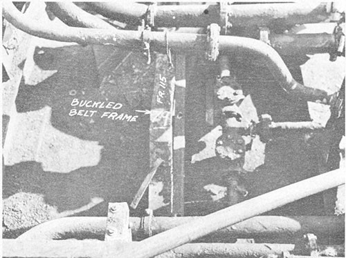
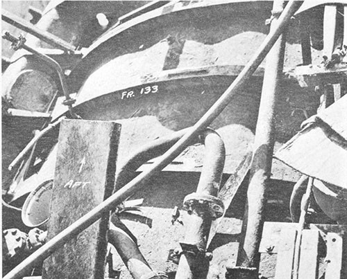
--75--
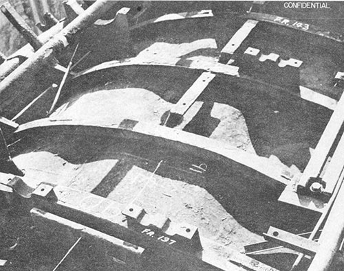
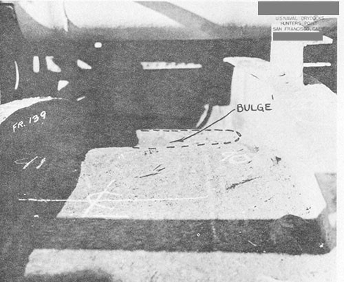
--76--
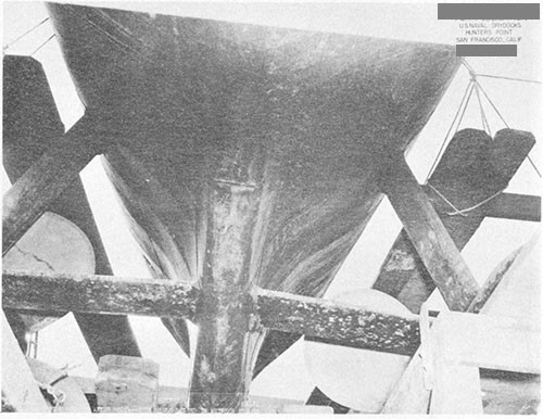
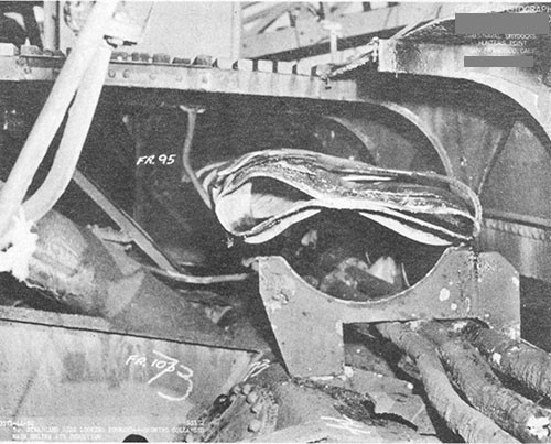
--77--
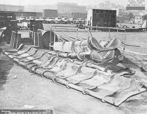
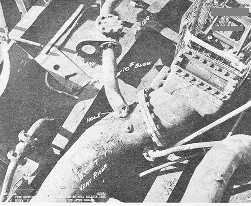
--78--
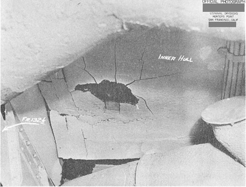
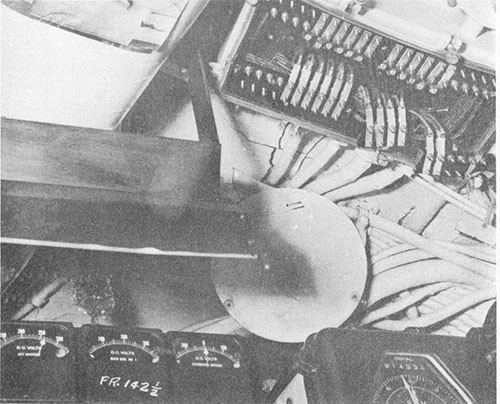
--79--
![Photos 7-11 and 7-12 [below]: SALMON (SS182). Side and front views showing displacement of brace for stem of No. 2 main engine inboard exhaust valve due to pressure hull distortion in forward engine room. Photos 7-11 and 7-12 [below]: SALMON (SS182). Side and front views showing displacement of brace for stem of No. 2 main engine inboard exhaust valve due to pressure hull distortion in forward engine room.](/content/history/nhhc/research/library/online-reading-room/title-list-alphabetically/w/war-damage-reports/submarine-report-vol1-war-damage-report-no58/_jcr_content/body/image_37.img.jpg/1443698526051.jpg)
![Photos 7-11 [above] and 7-12: SALMON (SS182). Side and front views showing displacement of brace for stem of No. 2 main engine inboard exhaust valve due to pressure hull distortion in forward engine room. Photos 7-11 [above] and 7-12: SALMON (SS182). Side and front views showing displacement of brace for stem of No. 2 main engine inboard exhaust valve due to pressure hull distortion in forward engine room.](/content/history/nhhc/research/library/online-reading-room/title-list-alphabetically/w/war-damage-reports/submarine-report-vol1-war-damage-report-no58/_jcr_content/body/image_38.img.jpg/1443698658198.jpg)
--80--
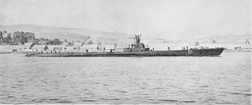
--81--
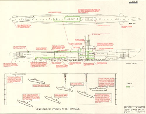
SECTION VIII
U.S.S. GRENADIER (SS210)
Loss in Action
Off Malaya
22 April 1943
| Class | SS198 |
| Builder | Navy Yard, Portsmouth, N. H. |
| Commissioned | 1 May 1941 |
| Length (Overall) | 307 ft. 2 in. |
| Beam (Extreme) | 27 ft. 3 in. |
| Submergence Depth (Designed Maximum) (Axis) | 250 ft. |
| Displacements | |
| Standard | 1475 tons |
| Emergency Diving Trim | 1980 tons |
| Submerged | 2359 tons |
| Draft (Mean, Emergency Diving Trim) | 16 ft. 8 in. |
| Type of Propulsion | Diesel Electric Reduction Drive |
| Main Engines (4) | Fairbanks-Morse 38-D-8-1/8 |
| Main Motors (4) and Generators (4) | Elliott Co. |
References:
(a) Enclosure (C) to ComSubPacAdmin ltr. FF12-10(A)/A4-1 (1)/A16-2, Serial 00349 of 21 September 1945 (Commanding Officer GRENADIER Statement Concerning Loss of Vessel).
(b) Account of Loss of GRENADIER as Related to Cdr. I.F. Duff, (MC), USNR, by Lt. Cdr. A. Toulon, Jr., USN (Engineer Officer) on 7 February 1946.
(c) ComSubPac Report Entitled "Enemy Anti-Submarine Measures", no date or file number given (Account of Loss of GRENADIER).
Photograph No. 8-1
8-1. On 21 April 1943, while operating off the Malay Peninsula during her sixth war patrol, GRENADIER sustained heavy damage to the after portion of the ship as the result of a Japanese aircraft depth bomb attack. The most serious casualty which occurred, and which directly caused GRENADIER'S loss, was the complete immobilization of her propulsion plant due to derangement of the main control cubicle and severe misalignment of the propeller shafting. All efforts by ship's force to effect emergency repairs were unsuccessful. Early the next morning, GRENADIER was abandoned and scuttled by her own crew to prevent imminent capture by an approaching Japanese merchant ship. This report is based on the information contained in the references. The references are accounts furnished from memory by various survivors upon their release from Japanese prisoner of war camps at the end of the war, nearly two and one half years after the action occurred. Therefore, the source data are not as complete and cannot be considered to have the same degree of accuracy as formal war damage reports written shortly after actions occurred.
8-2. The sixth war patrol of GRENADIER was conducted in the waters of the Indian Ocean off the west coast of the Malay Peninsula. Late in the evening of 20 April 1943, while making a surface search of an area about ten miles to the west of Lem Voalan Strait, GRENADIER sighted two Japanese merchant vessels. The moon being full and visibility conditions excellent, GRENADIER proceeded to circle astern of the ships with the intention of determining their course and speed. While still eight or nine miles away, however, she was detected and the enemy ships thereupon made a radical course change.
8-3. GRENADIER then proceeded to a position ahead of the target ships and submerged to await their arrival, but at early dawn of 21 April the Japanese again changed course before the range had been closed sufficiently to permit torpedo fire. When only the smoke of the ships was visible on the horizon, GRENADIER surfaced and commenced a run to a point which it was estimated would place her in a favorable position for attack if the enemy ships next changed course in conformance with known Japanese convoy doctrine.
8-4. At 0836, when still about 15 minutes running time from the intercept position previously selected to await the enemy, a Japanese single-engined plane was sighted approaching from the port quarter. GRENADIER thereupon made a quick dive.
8-5. When GRENADIER reached 90 foot depth, 15 degrees right rudder was ordered. At 0837, as the ship was passing 120 feet depth, a tremendous detonation occurred close over the maneuvering room and heeled the boat 10 or 15 degrees to port.1 Lighting, auxiliary power and main propulsion were immediately lost. Emergency lighting was switched on and functioned satisfactorily. GRENADIER continued on down while attempts were made aft to regain power. When a depth of about 200 feet was reached, word was received that a fire had started in the maneuvering room so the boat was set on the bottom in about 260 feet of water.
8-6. The bomb detonation was reported to have been centered about 70 degrees to starboard from the vertical above and abreast the after
____________
1 Japanese records obtained at the end of the war contain no mention of this attack.
bulkhead of the maneuvering room. The severity and extent of the damage indicate that the weapon was probably a 250 Kg. Mk. 2 antisubmarine depth bomb containing 317 pounds of Type 98 explosive. This is the largest depth bomb known to have been developed by the Japanese and was commonly used for anti-submarine work. The depth setting employed in this instance was probably that corresponding to the standard "25 meter" fuzing frequently used by the Japanese. This should have caused detonation in the vicinity of 70 to 80 foot depth or about 40 feet above and to starboard of GRENADIER's pressure hull abreast the after end of the maneuvering room. The Commanding Officer stated that the noise and jarring effect of the detonation on the ship were as though "two express trains collided". Beyond a few superficial lacerations and bruises there were no personnel casualties.
8-7. The fire in the maneuvering room was reported to have started as a result of the cutting and short-circuiting of the main motor power cables above the control stand when the pressure hull overhead dished in sufficiently to come in contact with the power cage of the main control cubicle, and also by arcing of contactors in the control stand itself. The burning material consisted of the hull insulation cork sheathing, electric cable sheathing, stores, cleaning rags and paint. Dense noxious smoke was generated in large quantities. When it became apparent that no immediate headway was being made in attempts to extinguish the fire, and with smoke spreading throughout the boat, the Commanding Officer ordered the maneuvering room sealed. About one-half hour later, the compartment was re-entered by a firefighting party using escape "lungs" as respirators to filter out the smoke and the fire was smothered with CO2 from portable fire extinguishers. At some time during this period two men were overcome by smoke. The escape "lungs" were used since rescue breathing apparatus was not available. It was reported that the "lungs" were clumsy and that difficulty was experienced in keeping the mouth-pieces in place.
8-8. The pressure hull plating and frames were severely dished inward from the after bulkhead of the engine room to the after bulkhead of the after torpedo room. Maximum dishing was sustained in way of the bulkhead separating the torpedo room and the maneuvering room, four to six-inch indentations occurring at the starboard forward end of the after torpedo room. The bulkhead itself was distorted and forced to port, apparently bending the port and starboard propeller shafts at both stern tubes, and the watertight door seat was sprung so that the door could not be completely closed. The maneuvering room control cubicle cage was twisted out of shape and deck plates and support frames were bent.
8-9. Although in no place was the pressure hull proper reported to have been torn or ruptured, there were at least three sources of major leakage into the interior of the boat. The first was through the maneuvering room air induction hull valve, its seat being so badly distorted that a two-inch stream of water poured through from the flooded topside engine induction piping onto the electrical equipment of the main propulsion control cubicle beneath. The second source of leakage was through the distorted riveted joints of the maneuvering room hard
patch and this also resulted in sea water spraying onto the control cubicle. It was reported that this hard patch was partially separated from the hull. The third source of major leakage was through the after torpedo loading hatch. The bossing structure supporting the hatch seat was distorted to such an extent that the torpedo loading hatch transverse compression strut was bent about 10 to 15 degrees from its normal centerline and the hatch opening became elliptical in shape rather than circular. The hatch cover lacked seating to the extent that the Commanding Officer reported he could insert his hand between the seat and the hatch cover. Almost half of the circumference of the hatch gasket was badly cut.
8-10. Upon extinguishing the fire in the maneuvering room, a bucket brigade was formed between the maneuvering room and the forward torpedo room in an attempt to keep the water level below the level of the main motors. Many men lost consciousness from heat prostration and physical exertion. Eventually, a jury rig was established so that electrical power for the drain pump could be taken from the forward battery and incoming water was thereafter kept to a satisfactory level by pumping alone. Every effort was made to protect the control cubicle and other electrical equipment in the maneuvering room from the shower of sea water through the hard patch and induction valve, but shields could not be effectively rigged due to overhead interference between the control cubicle and the hull. As a result, all vital electrical equipment in the control cubicle became saturated with salt water.
8-11. In the after torpedo room, all torpedo tubes were put out of commission, presumably due to misalignment of the entire tube nest and damage to stop bolts, torpedo guide studs, gyro setting spindles and blow and vent piping systems and fittings. Steering system hydraulic lines were ruptured. Many gauges were dismounted and deranged. Bunks and torpedoes were dislodged and thrown about.
8-12. Damage forward of the maneuvering room was apparently relatively minor. In the engine room, hydraulic lines to the main vent valves carried away. No other damage was reported in this compartment although there must have been at least considerable minor derangement of equipment, piping systems, gauges and instruments. In the crew's messroom, dishes and phonograph records were thrown about and broken. In the radio room, the radio receivers were dislodged from their mountings and the transmitter was knocked over. The radio gear was subsequently put back in commission. The insulators in the radio antenna trunk were also found to have broken.
8-13. The ship's force worked all day attempting repairs and restoring order where possible. No more enemy attacks were received. Efforts to restore propulsion power were considerably hampered by the continued intake of water over the control cubicle and by several minor electrical fires which started at various times.
8-14. During this period, breathing conditions became very trying for the eight officers and sixty-eight men aboard. The air conditioning
and ventilating systems were not working. The maneuvering room fire had created large quantities of irritative smoke and in addition had consumed some of the available oxygen from the atmosphere. About eight cans of carbon dioxide absorbent were spread out in the after battery compartment and oxygen was bled into the boat. Men not working were encouraged to lie down. Despite these measures the ship became very hot and humid and headaches were common.
8-15. At 2130, after 25 hours submerged, GRENADIER surfaced under cover of darkness in order to ventilate the boat and aid repairs by stopping the maneuvering room leakage. The ship was cleared of smoke at this time by running the main Diesel engines. After several hours' work a jury rig was established which enabled power to be supplied to the motors of one shaft. However, the shaft could be turned over only at very low speed, apparently due to severe stern tube or strut bearing misalignment or bending of the shaft itself. It was impossible to move the control stand levers into the second stage resistance. Approximately 2750 amperes were required to turn the shaft although the current normally required was only 450 amperes.
8-16. By about 0400 to 0500 the next morning, 22 April, all efforts to restore propulsion had proved of no avail and it became apparent that nothing further could be accomplished in view of the magnitude of the damage and the limited repair facilities available to the ship's force.
8-17. Plans were then made to rig a sail with the intent of moving the ship closer to the shore where the crew could be disembarked and the ship blown up. This scheme, however, was soon shown to be futile and was abandoned.
8-18. At about 0600 a ship was sighted proceeding from the northwest out of Lem Voalan Strait and shortly afterwards smoke from what appeared to be a patrol craft was sighted to the southeast. At this time GRENADIER could neither run nor fight. It was considered inadvisable to resubmerge since a stationary dive would have been required without power, there were several leaks of serious nature through the hull and the true trim of the boat was not known due to having transferred large quantities of water and the loss of fuel oil through ruptures in external tanks. Offensive action against the enemy was not possible since the three-inch deck gun had been damaged and torpedoes apparently could not be fired. The decision was therefore made to scuttle the ship. Classified papers were destroyed and radar, radio, sonar and TDC equipment was demolished.
8-19. While preparations were in progress for abandoning ship, a single-engined Japanese plane, similar to the one of the preceding day, commenced a run on GRENADIER from the port side but was forced away by the return fire from the two 20mm and two .30 caliber machine guns. The plane then made a second run on GRENADIER'S port side and was again fired upon. When directly overhead, the plane dropped an aerial torpedo which struck and detonated in the water about 200 yards from the ship. Subsequent information indicated that the pilot of the plane died that night as a result of wounds received from GRENADIER'S fire and a crash when landing at Penang.
8-20. The crew was then lined up at quarters forward of the conning tower, leaving one man below to open the tank vents. There being an insufficient number of life jackets available for all hands, mattress covers were inflated with air prior to abandoning ship. In addition, one rubber life raft was available for the sick and those who could not swim. When the ship from the northwest, an 1800-ton converted merchant vessel, arrived within two miles distance, all hands were ordered over the side and the man below opened the vents. GRENADIER sank quickly, stern first.
8-21. The entire complement, seventy-six men and officers, were taken aboard the Japanese merchant ship and subsequently landed at Penang, Malay States. Of these, seventy-two men survived to the end of the war. Prior to her loss, GRENADIER was officially credited by ComSubPac with sinking six ships (3 AK, 2 AP and 1 AO), a total of 40,700 tons, and damaging two ships (both AK), a total of 12,000 tons.
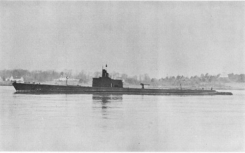
U.S.S. SCAMP (SS277)
Depth Bomb Damage Aft
Off Mindanao, P.I.
7 April 1944
| Class | SS212 |
| Builder | U.S. Navy Yard, Portsmouth, N. H. |
| Commissioned | 18 September 1942 |
| Length (Overall) | 311 ft. 8 in. |
| Beam (Extreme) | 27 ft. 3 in. |
| Submergence Depth (Designed Maximum) (Axis) | 300 ft. |
| Displacements | |
| Standard | 1525 tons |
| Emergency Diving Trim | 2050 tons |
| Submerged | 2415 tons |
| Draft (Mean, Emergency Diving Trim) | 6 ft. 10 in. |
| Type of Propulsion | Diesel Electric Reduction Drive |
| Main Engines (4) | Fairbanks-Morse 38-D-3-1/8 |
| Main Motors (4) and Generators (4) | General Electric Co. |
References:
(a) C.O. SCAMP conf. ltr. SS277/A16-3/A9, Serial 016 of 22 April 1944 (Report of War Patrol Number Seven).
(b) C.O. SCAMP ltr. SS277/P13-5, Serial 002 of 24 April 1944 (Report of War Damage).
(c) ComSubRon Eighteen ltr. FC5-18/L11-1/(SS277), Serial 0012 of 25 April 1944 (First Endorsement to CO. SCAMP War Damage Report).
(d) CinC U. S. Naval Drydocks, Hunter's Point conf. Report SS277-S8800-131693 of 9 April 1945 (Supplementary Report of SCAMP War Damage).
(e) BuShips Code 660u conf. Memorandum of 30 May 1944 (Report of Inspection of SCAMP War Damage at U.S. Naval Drydocks, Hunter's Point by Mr. W. H. Fifer, Bureau of Ships).
Photographs Nos. 9-1 through 9-15 (furnished by CO. SCAMP, CO. TANGIER (AV8) and Naval Drydocks, Hunter's Point)
PLATES IX-1 and IX-2
9-1. During her seventh war patrol SCAMP was attacked by a Japanese float plane shortly after submerging and sustained severe damage from a near-miss depth bomb detonation. The deformation which occurred to both the inner and outer hull structures as a result of this attack is the most severe known to have been survived by any U.S. submarine during World War II. It is considered remarkable that SCAMP was able to continue submerged operations after receiving the damage even though all propulsion power was lost for a fifteen-minute period during which the boat became heavy overall due to flooding of the main induction system, leakage of water into the hull and loss of fuel oil from a fuel ballast tank. This report is based on the information contained in the references. The Photographs were furnished by C.O. SCAMP, C.O. TANGIER (AV8) and U.S. Naval Drydocks, Hunter's Point. PLATES IX-1 and IX-2 were prepared by this Bureau and are based principally on the data contained in the enclosures to reference (d).
9-2. SCAMP arrived from her sixth war patrol at Milne Bay, New Guinea, on 6 February 1944. After a two-week refit by FULTON (AS11) followed by an intensive training period, SCAMP departed Milne Bay on 3 March for her seventh war patrol.
9-3. Although wide searches were conducted in her assigned area north of New Guinea, SCAMP made no enemy ship contacts during her first month on patrol. She then refueled at Langemak Bay, New Guinea, on 29 March and departed on 31 March for a new area in the waters between Mindanao and Halmahera Islands. The first enemy ship contact of the patrol was made on 4 April when a Japanese armed trawler was engaged by four-inch gunfire at long range. Two hits were scored on the trawler, causing a slight list and a fire aft, but the action was broken off when the deck gun on SCAMP failed to return to battery after 91 rounds had been fired.
9-4. Three days later, early on the morning of 7 April, SCAMP established contact with a Japanese convoy of three ships, but all efforts to reach a favorable attack position were unsuccessful. Her first attempt, a surface approach before dawn, was frustrated when the enemy made a radical change in base course. A second attempt was made by submerged approach later in the morning but range to the targets could not be sufficiently closed. Further action against this convoy was terminated when, at 0930, a large enemy task force, consisting of two heavy cruisers and four light cruisers screened by four destroyers and five planes, was sighted.
9-5. An approach on the new targets was commenced and an excellent firing position was gained for successive bow and stern tube salvoes. However, just prior to securing the final periscope observation before firing, SCAMP was detected by the enemy destroyer screen and forced to take evasive action. From then until noon she was sporadically depth-charged but no damage resulted. At 1405, after the destroyers had left the area, SCAMP surfaced to radio a contact report regarding the Japanese force but at 1407 an enemy bomber was sighted and she was forced to submerge immediately in order to avoid detection.
9-6. At 1423 SCAMP again surfaced to attempt to radio the contact report. Although continuous efforts were made, communications had not yet been established when, at 1543, a Japanese float plane, bearing 280° (T) and at an altitude of 1500 feet, was sighted diving on SCAMP from directly out of the sun. The plane was first detected by visual means when at a range of about 440 yards. At this moment SCAMP was proceeding on course 094° (T) at a speed of 15 knots with three engines on propulsion and one engine on charge. She was in a position about forty miles south of Mindanao, P.I., lat. 5° 02 'N., long. 126° 07 'E. The weather was clear, visibility excellent and the sea glassy calm.
9-7. SCAMP made a quick dive in an effort to avoid attack and word was passed to rig ship for depth-charging. The boat submerged with a 7 degree down angle at a speed of about 8 knots, swinging left with full rudder, and was passing forty feet depth when a single terrific explosion occurred off the port side. The resulting damage to SCAMP was extensive and serious. The entire ship vibrated and twisted for several seconds and all hands not holding on to something were thrown off their feet. The noise effect was described in reference (b) as "loud and deep".1
9-8. From available knowledge of types and sizes of bombs commonly carried by Japanese float planes on anti-submarine patrol at this period of the war, it is believed that the weapon used against SCAMP was probably a standard 60 Kg. Mk. 2 depth bomb containing 85 pounds of Type 98 explosive. Based on the damage inflicted and the known effect of underwater explosions on similar type structures, it is estimated that this 60 Kg. bomb probably detonated about frame 77 at a distance of approximately 15 feet from the port side of the pressure hull, centered vertically at the level of the tank tops and abreast FBT No. 5B and the interior transverse bulkhead separating the forward engine room and the after battery compartment. (PLATE IX-1).
9-9. A general survey of the overall damage sustained by SCAMP as a result of the bomb detonation is presented in PLATES IX-1, IX-2 and Photos 9-2 through 9-11. The immediate effects of the detonation which were of serious nature and which caused SCAMP's subsequent inadvertent maneuvers or determined the damage control measures which were employed in an effort to save the ship, are listed below:
(a) Simultaneously with the bomb detonation, a small electrical fire started in the propulsion control cubicle and dense toxic smoke was generated from burning phenolic material. This smoke filled the maneuvering
____________
1 This action was included in the list of anti-submarine attacks assessed as resulting in positive sinkings received from the Japanese at the end of the war. The exact translation of the Japanese comments on this attack is as follows: "Found a floating sub. Direct hit on the rear of the bridge and near-missed the side. A dense oil pool was created measuring 300 x 4000 meters. Air bubbles. The sub sank wriggling to the left". This statement indicates that two bombs were dropped although SCAMP's War Patrol Report and the nature of the damage sustained indicate that only one bomb detonated.
room and made personnel in that compartment violently ill. All propulsion power was deliberately cut off after the fire started in order to determine the extent of damage to the control cubicle and power circuits and avoid possible further damage. Propulsion was not restored until about 15 minutes later.
(b) The main engine air induction piping topside was torn open at the points of attachment to its welded supports in four places between frames 75 and 78 (Photo 9-5). These ruptures allowed the entire induction system to flood rapidly, causing a loss of buoyancy of about 14,000 pounds. Sea water then entered the interior of the pressure hull through the main induction drains and also around the forward engine room induction hull flapper valve, which would not tightly seat due to distortion of the adjacent hull structure. A total of about 10,000 pounds of water was taken into the bilges through these and other minor leaks.
(c) FBT No. 5B was torn open over a two-foot length between frames 79 and 80 at the knuckle between the margin plate and the tank top outer hull plating (Photo 9-7). This allowed the 7000 gallons of fuel oil in this tank to escape and be replaced with heavier sea water, causing an increase in weight of about 11,000 pounds.
(d) Power operation of the rudder was lost, presumably due to electrical contactors jarring open or fuses blowing in the steering motor control panel. The rudder therefore remained in full left position, which had been set on diving, until a shift was made to hand control about ten minutes later.
9-10. As a result of the sudden loss in buoyancy due to flooding of the main induction system, added weight due to intake of water into the pressure hull and displacement of fuel oil in FBT No. 5B with heavier sea water, both of the latter occurrences being relatively slow, SCAMP became heavy aft and started to settle fast, assuming a large up angle. The subsequent operations which were resorted to in a desperate effort to remain submerged can best be understood by a study of PLATE IX-2. When it is considered that the excess of weight over buoyancy resulted in the ship being about 15 tons heavy overall and heavy aft, and that no power was available with which to propel the ship so that the bow and stern planes and the up angle of the boat could be effectively used for aiding in depth control, the fact that SCAMP neither broached nor went excessively deep during this critical period is considered a great tribute to those who maintained depth control.
9-11. When SCAMP first began increasing depth rapidly, it was decided to blow a sufficient number of tanks to halt this movement. All main vents were still open for the boat had just submerged and the damage had occurred before they were closed. However, when the order was given and executed to close these vents by hydraulic power, nothing happened. It was then noticed that the shock of the detonation had caused the drum-type starter controller for the main hydraulic plant to move to the "off" position, thereby shutting off current to the hydraulic pump motor. The controller was immediately cranked to the "on" position, starting the motor, and all main vents were then
closed without difficulty.1 When 100 foot depth was reached, the negative tank was blown. At 175 feet, safety tank was blown. The boat still continued to sink, however, so when a depth of 290 feet was reached, air bubbles were put in all main ballast tanks. Although the boat now probably had well over 100 tons positive buoyancy, momentum carried her down to 330 feet where she finally stopped, hung for a brief period and then started to rise, still with a considerable up angle. In the meantime, all hands not required elsewhere had been sent to the forward torpedo room where they squeezed themselves around the torpedo tubes to add weight forward for trim control. Efforts were being made in the maneuvering room to determine the extent of damage to the control cubicle and power circuits before attempting to restore propulsion but personnel were seriously handicapped both by the presence of the dense phenolic smoke and the large up angle on the boat. The rudder was still hard over and consequently the boat continued turning.
9-12. SCAMP, now rising rapidly, was faced with the prospect of inadvertently broaching, and it was decided that if the boat passed 50 feet still going up, a battle surface would be made and the deck guns would be manned against whatever opposition might be encountered. However, by venting and flooding all tanks on the way up, the ascent was checked at 52 feet and the ship started down again. By alternately blowing and flooding tanks, SCAMP was able to remain submerged without power and went up and down three times in this manner. At about 1600, as the boat started down for the fourth time and with pressure in the air banks getting low, the maneuvering room personnel finished checking the main power circuits and the starboard shaft was brought up to turns for two-thirds speed.
9-13. With propulsion power now available, and presumably having gained better trim by maintaining a bubble in the safety tank and pumping or blowing the after trim tank during this period, the ship could now be controlled and shortly afterwards was leveled off at 150 foot depth. About five minutes after the starboard shaft was first turned over, the port shaft was also brought up to turns for two-thirds speed. The rudder was finally placed amidships by shifting to hand hydraulic control but only after the ship had made one complete circle. The sequence of events from the time of the bomb detonation to the restoration of propulsion power, as described in the above paragraphs, consumed about a fifteen-minute interval. Fortunately, no additional enemy attacks were made during this critical period although the trail of oil escaping from FBT 5B and air bubbles from the blowing operations must have disclosed SCAMP's whereabouts very plainly indeed. Presumably, the enemy plane had no more bombs or the pilot felt certain SCAMP had been destroyed.
____________
1 Drum-type starter controllers were particularly susceptible to mechanical troubles and shock damage. ShipAlts SS257 and SS261 of 5 and 10 October 1944, respectively, authorized the replacement of drum controllers for the hydraulic plant and trim pump motors with the much more satisfactory magnetic type push-button controllers.
9-14. SCAMP commenced evasive action, running at 150 foot depth, and probably still leaving a small trail of oil behind. At this time the ship was considerably out of final trim and very sluggish and hard to control. From 1755 to 1830, ten depth charges or bombs were heard detonating but all were well to eastward of SCAMP, the enemy obviously having lost all trace of her. It was fortunate for SCAMP that no enemy surface ship sonar-listening searches were conducted in her vicinity for one of the results of the bomb damage was a very high machinery noise level.
9-15. Although not important, it is interesting to note that when a bottle of "Chlorox" in the crew's washroom was broken at about this time, the resulting small release of chlorine gas was thought at first to have come from sea water leaking into the after battery. Both battery wells were checked, however, and found to be dry.
9-16. SCAMP remained submerged until well after dark and then surfaced at 2103. Upon reaching the surface and blowing tanks, the ship assumed a 17 degree port list. The heeling moment responsible for this excessive list was due chiefly to the following two reasons: (a) the fuel oil in port FBT No. 5B had been displaced with heavier sea water while the fuel oil in the corresponding starboard tank FBT No. 5A had remained intact; (b) sea water in port MBT Nos. 4B and 6B could not be completely blown upon surfacing since the division bulkheads between these two tanks and FBT No. 5B had pulled away from the hull, allowing air introduced into any of the three tanks to escape through the rupture at the tank top of FBT No. 5B and also through a leaking emergency vent valve and riser of MBT No. 4B. On SCAMP, of course, the exact reasons for the list were at this time unknown. All possible variable ballast water was shifted to starboard tanks immediately but this reduced the list only slightly. The loss of fuel oil from FBT No. 5B was first discovered when test cock samples showed that tank to be full of sea water. It was then decided to remove the vent riser blank from the corresponding starboard FBT No. 5A and allow the oil therein to escape during a dive so as to equalize the liquid loading.
9-17. Meanwhile, and in spite of the excessive list, SCAMP started both starboard main Diesels and cleared the area by proceeding south, running on one engine and charging batteries with the other. Starboard fuel tanks were put on service to reduce list by increasing salt water ballast on the starboard side. Low pressure blowers were run every thirty minutes.
9-18. Two men were sent into the superstructure in an attempt to remove the FBT No. 5A vent riser blank. They managed to insert and secure a crowbar under the riser blank but when a trim dive was made, at 0102 (8 April), in an effort to displace the fuel oil, it was found that the opening was insufficient to allow this. Therefore, at 0137, SCAMP surfaced and again men were sent aft in the superstructure to remove the riser blank. After about three hours work, the task was finally accomplished and, at 0455, another trim dive was made. This time oil poured out of FBT No. 5A. By 0555, test cock samples showed the tank to be clear of oil so SCAMP surfaced. The list was now reduced to 9 degrees port. Both FBT Nos. 5A and 5B were left rigged as free flooding tanks.
9-19. SCAMP's fighting effectiveness was reduced as the result of the attack to defensive action only. Although all torpedoes could be fired, further offensive action would have been inadvisable due to slow diving time, poor depth control, high noise level, and the decreased factor of safety at deep depths because of the hull damage. It was therefore decided to terminate the patrol at once.
9-20. SCAMP proceeded to Seeadler Harbor, Admiralty Islands, for temporary repairs and arrived there on 16 April 1944. From 10 April until arrival at Seeadler, SCAMP was escorted by DACE (SS247). Daylight hours were spent submerged during the entire run. Diving was slow and the boat was still somewhat difficult to handle submerged due to inability to maintain proper trim control. The return trip was uneventful except for numerous minor electrical casualties. Constant efforts were made by ship's force to stop leaks and repair damage where possible. The radio had been put out of commission due to a damaged coupling on the TBL motor-generator but satisfactory repairs were made by 10 April and communications were reestablished. On 11 April, a small fire started in the pump room air conditioning panel but this was soon brought under control and extinguished. On 14 April electrical power was lost on the bow planes for reasons not reported, but was restored within two hours. On 15 April a 190 volt ground developed in the after battery. Inspection revealed zero resistance grounds in three port cells, Nos. 106, 120 and 121, although it was reported that no loss of electrolyte occurred. These cells were by-passed and no further difficulty was experienced.
9-21. Damage to the superstructure is illustrated in Photos 9-2 and 9-3. The port superstructure deck and side plating were completely carried away in the vicinity of FBT No. 5B and the wood and steel decking was demolished or torn up across the width of the ship over a length of about ten feet. Aside from this immediate area, the only superstructure damage which occurred was minor distortion of the bridge fairwater plating and the bridge steps.
9-22. The tearing of the main induction line at the point of attachment of its welded supports (Photo 9-5) is an excellent example of the type of damage to be expected when a relatively non-rigid structure having a large area exposed to explosive loading, in this case the induction piping, is restrained from movement by welded attachment over small areas to relatively much stronger and more rigid members, in this case the bracket supports. The induction piping naturally tended to move bodily when struck by the shock wave from the bomb detonation, and was restrained only by its widely separated welded supports. The stress concentration at these points exceeded the ultimate shear strength of the pipe wall and consequently tearing resulted. A better design would have been one with small fillet welds, between the supports and the pipe, which would have failed before tearing the pipe walls. To prevent a recurrence of this casualty on SCAMP and other submarines, immediate replacement of all such directly welded supports on external induction and ventilation lines with non-welded belly-band type supports was
authorized.1 The partial collapse of the induction piping between welded stiffening rings (Photo 9-6) illustrates the great effect such stiffeners have in increasing the collapse strength of circular pressure vessels. It should also be noted that the collapse occurred only on the side directly facing the bomb detonation.
9-23. Severe deformation was sustained by the upper portion of the outer hull plating and framing between frames 72 and 82, port, over a longitudinal distance of about 30 feet (Photo 9-4 and PLATE IX-1). Minor distortion occurred forward to frame 69 and aft to frame 85. Tanks in this area are MBT No. 4B, FBT No. 5B and MBT No. 6B. The maximum indentation in the outer hull plating was about 12 inches, occurring between frames 78 and 79 at the tank top of FBT No. 5B (Photo 9-3). The average indentations of other areas of heavy damage in the outer hull were between 4 and 7 inches.
9-24. The outer hull plating was ruptured in only one place, a two-foot longitudinal tear which occurred at the tank top of FBT No. 5B between frames 79 and 80 (Photo 9-7). This was caused by excessive stress concentration at the tank top knuckle due to structural discontinuity at the bracket connection scarfing the outer hull frame within the tank to the topside pressure hull frame outside the tank (See sketch in PLATE IX-1).2 The fact that only one rupture occurred in the outer hull although distortion of structure was severe, and even that one rupture being attributable to basic design, demonstrates the great ability of such welded structures to deform without loss of their watertight integrity.
9-25. The wing bulkheads at frames 75 and 80, extending from the inner to the outer hull and separating MBT No. 4B, FBT No. 5B and MBT No. 6B, were extensively buckled. Both of these bulkheads, together with their stiffeners, were torn loose from the inner hull, thereby intercommunicating all three tanks (Photo 9-10). This allowed fuel oil from FBT No. 5B to reach MBT Nos. 4B and 6B and prevented the complete blowing of the latter two tanks, since FBT 5B was torn at the top and thereby opened to the sea. Inability to blow these port tanks
____________
1 Authorized by BuShips ltr. SS/S38-1(515-815) of 7 June 1944.
2 To diminish the possibility of this casualty occurring again to SCAMP or other applicable submarines, BuShips conf. ltr SS/S11-2(515) of 27 June 1944 authorized the modification of such bracket connections to reduce stress concentration under high explosive loading conditions. This was accomplished by installing a small reinforcing plate so as to lap the standing flanges of the pressure hull frames onto the tank tops instead of terminating them abruptly at the tank top knuckle as provided in the basic design. Priority was given to those frames in way of normal fuel and fuel ballast tanks. See sketch in PLATE IX-1.
contributed to the large list assumed by SCAMP on surfacing. In addition, the flood valves for MBT No. 4B and FBT No. 5B were twisted off their seats.
9-26. The structural deformation which occurred in the inner or pressure hull of SCAMP was the most severe known to have been survived by any U.S. submarine during World War II. The pressure hull plating (27.5-pound medium steel) was dished in from frames 69 to 84, a distance of 37 feet. Average indentations in the worst areas were of the order of 4 to 5 inches with a maximum indentation of 7-1/8 inches occurring near the tank top margin plate at frame 79-1/2 (Photos 9-9 and 9-11). Graphical presentation of the pressure hull deformation over this area is included in PLATE IX-2. In no place was the pressure hull ruptured. Pressure hull frames (6" x 3-3/8" x 14.75-pound I-beams), secured to the hull with 5/16" fillet welds at the inboard flange toes, showed definite distortion throughout the areas of severe damage and in four places, frames 73, 74, 76 and 79, were torn from the inner hull when the latter dished inward (Photo 9-8). As mentioned above, tank bulkheads at frames 75 and 80 also were torn away from the inner hull (Photo 9-10). It is amazing that SCAMP's pressure hull retained sufficient strength to permit operation without collapse at a depth of about 330 feet subsequent to the damage.
9-27. Damage naturally was sustained by valves, fittings and piping systems attached to or passing through the pressure hull and outer tank boundaries in way of deformed areas, but was relatively minor considering the severity of the structural damage. MBT No. 4B vent riser leaked at the flanged connection with its tank top. Main vents for MBT No. 4B and safety tank leaked. The emergency vent for MBT No. 4B also leaked and its operating gear was pulled out of line. Due to the extreme indentation of the pressure hull at that location, the emergency vent operating gear for FBT No. 5B was bent 45 degrees out of line and forced in hard against the scavenging blower of No. 2 main engine (Photo 9-12). This vent valve was later opened by cutting a hole in the tank top. The 3000-pound high pressure air line leading from the air flasks in MBT No. 4 was bent between the inner hull and the hull stop valve but no leakage resulted either here or anywhere else in the entire high-pressure air system, although external air banks were subjected to considerable explosive loading in way of the damage. A fuel oil transfer line and a fuel oil compensating line inside the pressure hull abreast FBT No. 5B were bent and twisted but did not leak. Although hydraulic lines in the forward engine room were bent, there were no hydraulic leaks anywhere in the boat. Minor leakage occurred at a fresh water line fitting in the crew's washroom but this was easily repaired. Perhaps the most serious piping casualty was the flattening of the No. 2 sanitary tank overboard discharge line which prevented blowing the tank. This discharge line also leaked at its flanged seachest connection to the outer hull in way of MBT No. 4. The
seat of the forward engine room air induction hull valve was slightly distorted and allowed considerable water to enter the compartment from the flooded induction piping topside. This leakage was later reduced by taking up hard on the valve with a chain fall.
9-28. Damage to machinery was surprisingly minor considering that the detonation occurred abreast the forward engine room. The scavenger blower for No. 2 main engine was misaligned, possibly by shock but more probably as a result of the inward bulge of the pressure hull pushing the operating gear of FBT No. 5B emergency vent valve into the blower housing (Photo 9-12). No attempt was made to run No. 2 main engine after hearing noises in the scavenging blower spiral impellers when the engine was jacked over. No. 3 main engine blower also sustained minor misalignment of the drive gears but this was not serious enough to prevent operation of the engine. No. 1 detached fuel oil pump was deranged so that it would not supply proper pressure but the exact nature of this casualty was not reported. No. 1 lubricating oil purifier was thrown out of alignment. No other damage, except for minor electrical derangements, occurred to auxiliary machinery anywhere in the boat. Machinery piping damage was limited to a ruptured line from No. 2 main engine exhaust to the compensating system.
9-29. Electrical damage, although in itself quite minor, had very serious effects on ship control due to the generation of toxic smoke by the small electrical fire in the maneuvering room. This fire was limited to a small rotary clutch by-pass switch (BuShips Standard Plan 9-S-4474-L) in the No. 4 generator field circuit of the main control cubicle. This switch was mounted in a closed phenolic frame and the burning of only a small portion of this phenolic material created the large volume of dense smoke (Photo 9-13)1. No report is contained in any of the references as to the cause of the fire but the following hypothesis is believed to be a plausible explanation. With the type of General Electric control cubicle installed on SCAMP, it was not necessary to clear the generator connections before shifting propulsion motors to battery power.2 Therefore, during quick dives, it was the custom with such propulsion controls to first change to battery power and then to de-energize all generator circuits. It appears probable that some metallic object, dislodged by the shock, fell through the cubicle and momentarily shorted the excitation supply to the No. 4 generator field. This would cause excessive current to flow through the clutch by-pass switch, which is used to by-pass the regular excitation contactors when two or more generator field rheostats are clutched together. The excessive current would cause the switch to arc and could account for the ignition of its phenolic case. Failure of this switch on SCAMP also short-circuited the Nos. 2 and 4 generator field supply and return leads and the port motor electrical interlock. Actually, both the port and starboard propulsion plants were undamaged and could have been kept in continuous operation. All power was cut off by ship's force, however, when smoke and flame were seen to issue from the control cubicle since it was quite correctly felt that the circuits should be checked through to
____________
1 For further discussion, see paragraph 19-13.
2 Current General Electric Co. submarine propulsion control designs are provided with interlocks which require all generator connections to be opened before shifting to battery power.
determine the nature of the casualty in order to prevent possible further damage to the motors and control equipment. Upon completion of this check, which took about 15 minutes due to the presence of the toxic smoke, the starboard plant was started simply by operation of the controllers and shortly afterwards the port plant was started in similar manner after resetting the electrical interlock by hand. With the exception of the fire in the clutch by-pass switch, there was no apparent misalignment, distortion or maloperation of any part of the control cubicle. It is interesting to note that the battery tank contactors did not open, although those in the after well had not been by-passed.
9-30. Auxiliary and lighting power were not lost at any time. Numerous clips holding cables to bulkheads were jarred loose in the forward engine room and crew's washroom. Only one battery ventilation duct fractured and this occurred in the after battery compartment. In the forward battery compartment, the battery fresh water tanks shifted forward about two inches. Damage to the batteries themselves was limited to the three cells having full grounds mentioned in paragraph 9-20 above. The forward battery air flow meter would not function, apparently due to a clogged or crushed line. The supply ventilation blower panel in the port side of the forward engine room was disabled and all leads were pulled loose. The ship's force later constructed a jury rig to provide power to this blower. The hot water heater panel located in the crew's washroom was completely wrecked when it was crushed against the hot water tank by the inward movement of the pressure hull in that area. Although galley equipment was damaged, also by dishing of the pressure hull, no grounds occurred in electrical circuits.
9-31. A moderate amount of damage occurred to electronic equipment and associated gear. The SJ radar antenna mast was slightly sprung but could be trained. Numerous tubes in the SJ receiver indicator were jarred loose and the feeder unit dipole sleeve was bent, causing a fluctuating pulse during antenna train. One tube in the SJ oscillator converter was broken and the lobe switching circuit was inoperable for reasons not reported. In spite of the above difficulties, repairs were made and the SJ radar was placed back in commission. The antenna coupling gap on the BN radio transmitting and receiving gear closed under impact, causing a high voltage arc. As mentioned previously, the coupling on the TBL radio motor generator jarred loose but was subsequently repaired and radio communications were restored. The forward insulator on the center radio antenna topside fractured and this antenna had to be cut down upon surfacing. The 1MC general announcing system could not be operated due to derangement of both signal generators.
9-32. Other miscellaneous items of damage not covered elsewhere are listed below. The gyrocompass repeater located on the bridge was knocked out of its gimbals and was suspended only by its electrical cable lead but still continued to function. The valve stem extension arm on the 10-pound blow stop valve for MBT No. 2B forward was found to be missing. Although the outside temperature element on the bathythermograph was torn loose, this equipment remained operative.
9-33. At Seeadler Harbor, Admiralty Islands, repair forces from TANGIER (AV8) and JENKINS (DD447) patched the tear in FBT No. 5B, cleared away the superstructure wreckage, installed a new temporary superstructure, and placed No. 4 engine and generator back in commission. SCAMP departed Seeadler Harbor on 20 April for Milne Bay, New Guinea, arriving on 22 April 1944. Here she was docked in the ARD9 and temporary structural repairs were made to the bulkheads and frames which had been torn from the pressure hull.
9-34. SCAMP then returned to U.S. Naval Drydocks, Hunter's Point, arriving on 18 May 1944. Complete war damage repairs (Photo 9-14 and 9-15) together with routine overhaul and outstanding alterations were accomplished there and SCAMP was returned to service on 8 September 1944, five months after the action occurred.
9-35. SCAMP was lost on her next war patrol. Information made available by the Japanese upon termination of the war indicates that she was probably sunk while on lifeguard duty off Tokyo Bay as the result of one or more of three depth charge and depth bomb antisubmarine attacks conducted in her area during the period 11 to 16 November 1944. In the seven patrols completed before her loss, SCAMP was officially credited by ComSubPac with sinking six ships totaling 49,000 tons (2 AK, 2 APK, 1 SS, 1 AO) and damaging eight other ships totaling 40,400 tons (2 AK, 2 AO, 1 DE, 1 AP, 1 CA, 1 trawler).
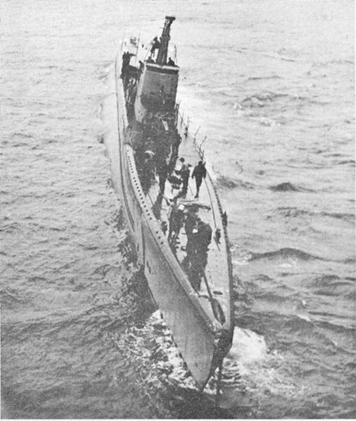
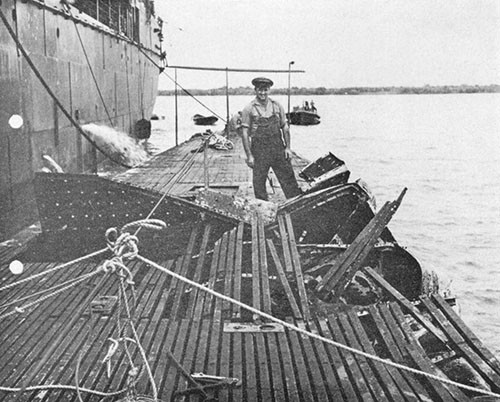
--101--
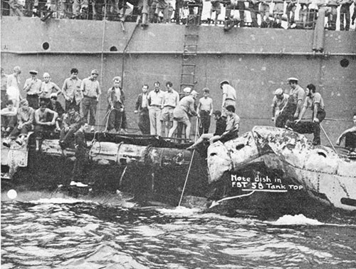
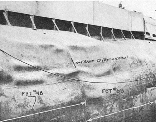
--102--
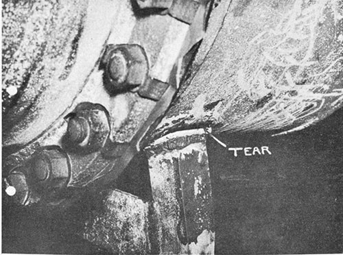
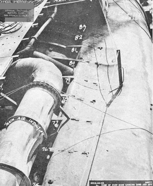
--103--
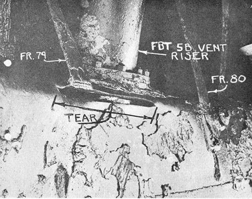
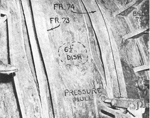
--104--
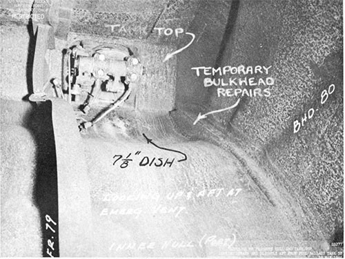
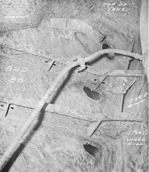
--105--
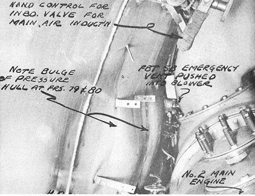
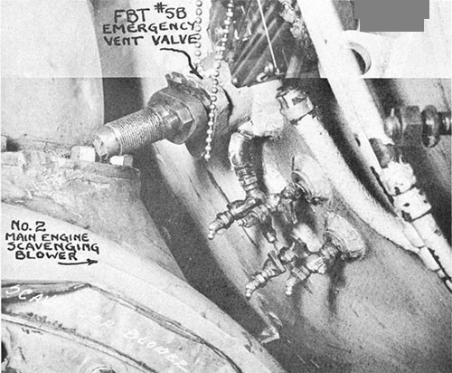
--106--
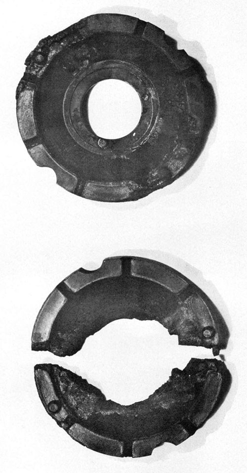
--107--
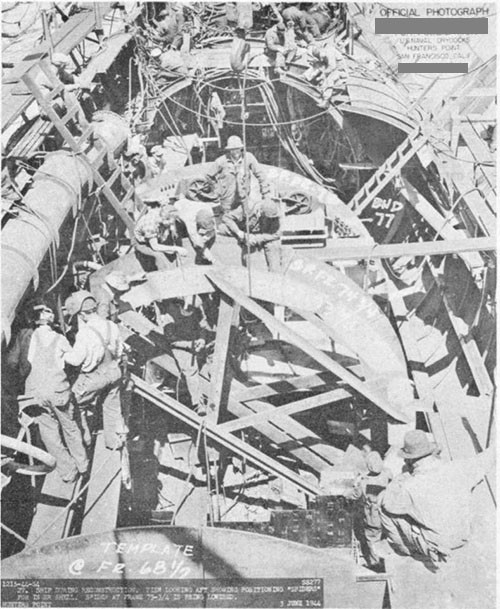
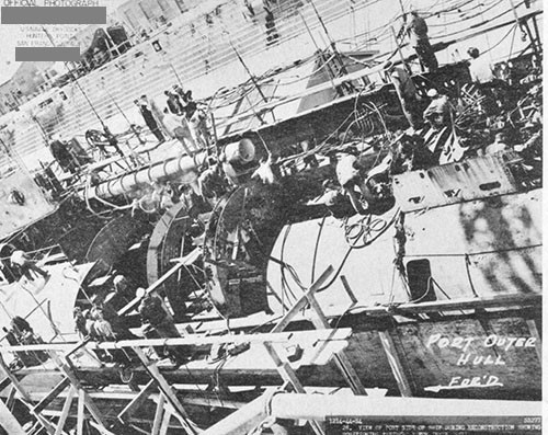
--108--
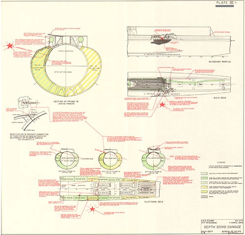
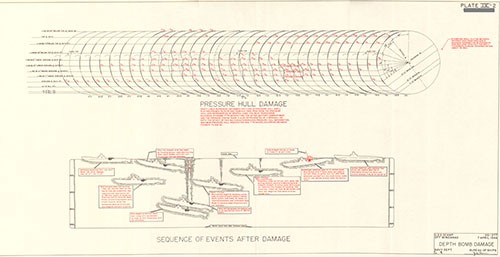
U.S.S. TANG (SS306)
Loss in Action
Formosa Strait
24 October 1944
| Class | SS285 |
| Builder | U.S. Navy Yard, Mare Island |
| Commissioned | November 1943 |
| Length (Overall) | 311 ft. 8 in. |
| Beam (Extreme) | 27 ft. 3-1/4 in. |
| Submergence Depth (Designed Maximum) (Axis) | 400 ft. |
| Displacements | |
| Standard | 1525 tons |
| Emergency Diving Trim | 1956 tons |
| Submerged | 2408 tons |
| Draft (Mean, Emergency Diving | 16 ft. 2 in. |
| Type of Propulsion | Diesel Electric Reduction Drive |
| Main Engines (4) | Fairbanks-Morse 38-D-8-1/8 |
| Main Motors (4) and Generators (4) | Elliott Co. |
References:
(a) C.O. TANG conf. ltr. SS306/A-16-3 of 10 September 1945 (Report of War Patrol Number Five and Loss of Vessel).
(b) BuMed conf. ltr. BLK:II, Serial No. 0356 of 29 July 1946 (Submarine Escape in World War II).
(c) Interviews with Various TANG Survivors by Cdr. I. F. Duff, (MC), USNR.
Photograph No. 10-1 (Torpedoing of U-977 - Associated Press) and 10-2. PLATE X
10-1. On 24 October 1944, during her fifth war patrol, TANG was sunk in Formosa Strait as a result of the malfunctioning of one of her own torpedoes which made a circular run and returned to strike the hull abreast the after torpedo room.1 The resulting detonation caused the ship to plunge by the stern within a few seconds.
10-2. This report is based on the information contained in the references. The first portion of reference (a) is a narrative of TANG's fifth war patrol up to the time of her loss and was written from memory by the Commanding Officer upon his release from a Japanese prisoner of war camp at the end of the war, approximately one year after the action took place. The second portion of reference (a) is a reconstruction of the events which occurred in TANG after the torpedo struck. Since the Commanding Officer was washed off the bridge when the ship sank, this portion is based on the stories of the eight other survivors as related to him at the first opportunity after their capture by the Japanese; five of the eight having gone down with the boat and later making individual underwater escapes from the forward torpedo room. This reference, although understandably not as complete as formal war damage reports covering actions in which a submarine returns to base and damage can be thoroughly investigated, is an excellent presentation of the available data and is the only account in U.S. Naval history of the events inside a war-damaged U.S. submarine during and after its sinking. References (b) and (c) cover the escape problem facing the men trapped within the boat and the procedure used by those few who made successful escapes. These latter two references are based upon personal written and oral accounts of the survivors as related to representatives of the Bureau of Medicine and Surgery. The photograph of the torpedoing of U-977 is included to illustrate the magnitude of TANG's disaster. The PLATE was prepared by the Bureau.
10-3. The fifth war patrol of TANG was conducted in the Formosa Strait. This area was assigned in order that TANG would be in a position to intercept any Japanese shipping which might retire from Formosa as a result of the carrier strikes against that Island by the Third Fleet on 12 through 14 October 1944, and also to intercept any enemy reinforcements which might pass through Formosa Strait in support of the Philippine campaign which commenced with the Leyte Island landing on 20 October 1944.
10-4. After normal refit at the Submarine Base, Pearl Harbor, TANG departed for Formosa Strait via Midway on 24 September 1944 and reached her patrol area on 10 October. On 11 October TANG sank one large and one medium-sized cargo ship off the west coast of Formosa, the first by a dawn torpedo attack while submerged and the second by a night torpedo attack while surfaced. On 12 through 14 October, the period of the Third Fleet air strikes against Formosa, numerous searches were conducted along likely enemy shipping retirement lanes
____________
1 There is evidence to indicate that the loss of TULLIBEE (SS284) on 26 March 1944 was similarly caused by a circular run of her own torpedo. See Appendix II.
to the China coast but no contacts were established. From 14 to 22 October, although several enemy ships were sighted, range to the targets could not be sufficiently closed and consequently no attacks were made. Shortly after midnight on 22 October, radar contact was established with a heavily escorted enemy convoy composed of three large tankers, a large cargo ship, and a medium-sized transport. All ships were heavily loaded and were apparently bound for support of the Philippine campaign. TANG executed a spectacular close range night surface attack, sinking all five ships of the convoy within ten minutes of firing her first torpedo and then cleared the area at full speed, leaving the escorts apparently engaged in a gun duel with one another.
10-5. Following the action of 23 October, TANG proceeded north of Formosa Strait for deeper water and then headed toward the shallow protected waters along the China coast on the theory that, due to her recent successes, all subsequent Japanese shipping passing through the Strait would be routed close inshore. This belief proved correct, for in the early evening of 24 October radar contact was established with a large Japanese convoy hugging the China coast and located about midway between Foochow and Amoy. The convoy was proceeding south at a speed of about twelve knots, apparently also headed for the Philippines, and consisted of at least fourteen large, heavily-loaded ships in column escorted by at least one destroyer and twelve destroyer-escorts. Some of the escorts were to seaward of the convoy while others were on the landward side.
10-6. TANG closed for a night surface attack using radar ranges and TBT bearings, but her presence was apparently suspected for two of the seaward enemy escorts commenced to run on opposite course to the convoy column, firing sporadic and wild bursts of small and medium caliber projectiles. As TANG continued to approach, one of the enemy escorts illuminated the convoy column with a large searchlight while signalling and this had the favorable effect of increasing target ship visibility. Three of the leading ships, a large transport, a medium-sized transport and a large tanker, were selected as the initial targets and, at ranges varying from 900 to 1400 yards, TANG fired three slow deliberate salvos of two torpedoes each per ship. In spite of the enemy having had apparent early knowledge of TANG's presence, no evasive tactics were employed by any of the ships up to this time. All torpedoes ran true to their targets, sinking the three ships almost immediately. Meanwhile, TANG paralleled the convoy to search out the next two targets. A tanker and a transport were selected for stern torpedo attack and three torpedoes were fired at ranges between 600 and 700 yards. The escorts had now stopped their warning tactics and were directing close salvos at TANG. Just after firing at the transport, a destroyer crossed close to the stern of that ship and headed directly for TANG. The first torpedo hit the tanker, which was apparently loaded with gasoline, and a tremendous explosion resulted. The second torpedo was observed to hit the transport and an instant later the destroyer blew up, either intercepting the third torpedo or cross fire from two enemy escorts which were bearing down on TANG's beam. Only the transport remained afloat and she was apparently stopped dead in the water.
10-7. TANG cleared the immediate area at flank speed, still on the surface and untouched by the enemy gunfire. When 10,000 yards distant from the enemy escorts, a halt was made to survey the situation and to recheck the last two torpedoes remaining on board. About one hour was spent on this work, the torpedoes being partially withdrawn from their tubes, batteries ventilated, gyros inspected and the steering mechanism observed to be operating freely. The two torpedoes were then reloaded in forward tubes Nos. 3 and 4 and TANG commenced a cautious approach to again attack the crippled transport, which was now observed to be lower in the water but definitely not sinking. Since two enemy escorts were patrolling to seaward of the transport, TANG made a wide sweep and came in very slowly to escape detection by sonic listening gear. Upon reaching a favorable position, the twenty-third torpedo was fired at the transport from a range of about 900 yards. Ship speed at this time was about six knots and the heading was conned for zero gyro angle setting on the torpedoes.
10-8. When the phosphorescent wake of the twenty-third torpedo was observed heading true for its intended point of aim on the target transport, the twenty-fourth and last torpedo was fired. This torpedo assumed an erratic course immediately upon leaving its tube and curved sharply to the left in a tight turning circle, broaching during the first part of its turn and porpoising during the remainder.1 Due to the phosphoresence of its wake, the torpedo was observed through 180 degrees of its turn. As soon as the erratic behavior was noted, which was almost immediately after the torpedo was fired, TANG went to emergency speed and partially executed a fishtail maneuver in a futile effort to clear the turning circle. This resulted only in the torpedo striking the boat farther aft than would have been the case had no evasive action been taken. The twenty-fourth torpedo, as were all those carried by TANG on this patrol, was an electric-driven Mk. 18, Mod. 1, fitted with a Mk. 18, Mod.1 warhead containing 570 pounds of TPX (equivalent in damaging effect to approximately 850 pounds of TNT).
10-9. The torpedo struck TANG on her port side aft in the vicinity of either the after torpedo room or the maneuvering room, about twenty seconds after being fired. The exploder mechanism (Mk. 8) used in the Mk. 18, Mod. 1 torpedo warhead is an inertia type which fires by impact from any angle and the time delay between receiving an impact blow and detonation of the warhead is so slight that the fuzing may be considered as instantaneous. It is therefore probable that the torpedo detonated on contact with the outer hull if it struck in way of the maneuvering room or with the single hull (pressure hull) if it struck in way of the after torpedo room. The Mk. 8 exploder mechanism arms itself by an impeller driven gear train, the impeller being caused to revolve by the ahead motion of the torpedo through the water. Arming of a Mk. 18 torpedo at its rated speed of about 29 knots should normally occur in approximately 200 yards or about 12 seconds running time. Based on studies of torpedo war damage experience with surface vessels, it is estimated that the torpedo detonation probably caused complete destruction of a section of TANG's pressure hull extending
____________
1 A torpedo anti-circular-run device is currently being developed by the Bureau of Ordnance to prevent recurrence of such malfunctioning.
over a longitudinal distance of at least 25 feet on the port side and extending in depth almost through to the opposite side of the hull, if in fact the hull itself was not completely severed (Photo 10-1).
10-10. Sufficient information is available to permit a fairly complete description of the events which occurred in TANG following the detonation. The boat as a whole was violently whipped. One survivor (conning tower) stated: "With the explosion of the torpedo, the boat seemed to bounce up and down". Personnel as far forward as the control room sustained broken limbs and other injuries. Pipe lines fractured, deck plates lifted up and lightly attached fittings and loose gear were flung about. The propulsion plant was destroyed instantly and men watching the pitometer log in the forward torpedo room noted that the boat lost all forward motion within a few seconds. The after torpedo room, maneuvering room, after engine room, and probably all adjacent tanks flooded rapidly. The watertight door in the after bulkhead of the forward engine room was closed with difficulty against the inrushing water from the after engine room, but not until the forward engine room had been half flooded. There were no survivors from the three after compartments. The ship apparently settled slowly for a few seconds and then plunged rapidly by the stern. Reference (a) states that "TANG sank by the stern much as you would drop a pendulum suspended in a horizontal position". Three of the nine officers and men on the bridge were thrown clear or were washed over the side as the boat sank and managed to stay afloat until rescued by the Japanese about eight hours later. Nothing is known of the fate of the other six men on the bridge. No lookouts survived and it is possible that they may have been unable to extricate themselves from or were injured by the periscope shear guard rails and were carried down with the ship. Communications were maintained between the conning tower and bridge until the ship plunged but there was insufficient time to carry out an order to close the upper conning tower hatch. Water poured through this open hatch and completely flooded the conning tower within a matter of seconds after it went below the surface of the water. One officer subsequently made a successful underwater "free" escape from within the flooded conning tower and it is known that one man was thrown through the lower conning tower hatch into the control room by the shock of the detonation, breaking his arm in doing so. Personnel in the control room succeeded in closing the lower conning tower hatch to prevent the inrush of water into the lower compartment. The hatch had been damaged, however, and leaked badly, causing the control room and pump room to flood slowly.
10-11. Although TANG's stern plunged to the bottom, the buoyant force of the intact amidships and forward compartments and tanks was such that the bow remained on the surface, the boat assuming a "spar buoy" position with an up angle of approximately 40 degrees. The officer who escaped from within the conning tower stated that upon reaching the surface he observed about 25 feet of the bow projecting above water. Within the ship, all loose gear fell to the after ends of each compartment and all hands held onto anything they could grasp. Some lost their footing and were thrown aft.
10-12. The men in the forward torpedo room, about ten in number, had secured their compartment shortly after the detonation occurred
and after vainly attempting to contact other compartments by phone came to the conclusion that the after part of the ship was destroyed. They discussed the possibility of escaping at once through the empty forward torpedo tubes but decided against that course because they could hear depth charges and feared the bow would be shelled.1
10-13. Personnel in the control room had also secured their compartment immediately after the detonation but possessed somewhat more complete information as to the extent of damage. Their prompt execution of damage control measures had established boundaries sufficient to prevent further rapid intake of water and they realized that some of the men trapped within the boat might be able to escape through the one remaining intact escape trunk in the forward torpedo room. To prevent the possibility of damage to the exposed bow by enemy action, and to facilitate escape operations by removing the excessive up angle, it was decided to sink the bow and level off. Therefore, about fifteen minutes after the initial damage occurred, TANG was deliberately bottomed by flooding the No. 2 group of main ballast tanks. Hydraulic power not being available, flooding of these tanks was accomplished by manual operation of the vent valves in the overhead of the control room.
10-14. Meanwhile, classified publications were being destroyed by burning, at first in the control room and later in the forward battery compartment when the water level in the control room made it necessary to evacuate and seal that space. The survivors from the control room and forward battery compartment, about fifteen men in all, then proceeded to the forward torpedo room, carrying their injured in blankets. When the door to the forward torpedo room was opened, the difference in air pressure between the two compartments due to leaking air systems amidships was such that those men near the door were literally blown into the torpedo room.
10-15. About one-half hour later, the survivors from the forward engine room and after battery compartment decided to attempt to reach the forward torpedo room. This group consisted of about twenty men, two of whom were injured. They discovered by peering through the
____________
1 Based on the reports that TANG assumed a 40 degree up angle with about 25 feet of the bow exposed, the outer doors of the torpedo tubes would have been slightly below the surface of the water at this time and escape through the tubes would therefore have been difficult, if not impossible. There are two instances, however, where such escapes have been accomplished from U.S. submarines. (1) S-5 sank in 194 feet of water off the Delaware Capes on 1 September 1920, due to internal flooding through maloperation of the induction valve. The crew managed to blow the stern to the surface and with great effort cut a small hole in the shell above the waterline. All hands were released about 51 hours later when an escape access was cut in the exposed stern by the crew of the steamship GENERAL GOETHALS. (2) On 7 December 1921, S-48 sank in 67 feet of water while on trials off Bridgeport, Connecticut. The engine room, motor room and steering room were flooded due to neglecting to replace a manhole cover on No. 5 port ballast tank. The bow was blown to the surface and all 41 men aboard escaped through a torpedo tube.
eye-port in the watertight door to the control room that water in that space had already flooded above the door level. On testing the bulkhead flappers in the ventilation piping they found the water not yet at this height. They therefore opened the bulkhead door, letting the water race through, and then proceeded to the forward torpedo room. When these men first attempted to open the door to the torpedo room, two men in the torpedo room tried to get them to crack the door slowly so as to gradually equalize the large difference in air pressure between the two compartments. The men in the forward battery compartment, however, did not understand the signals and thought they were being deliberately kept out. They forced the door open and, being accelerated by the air pressure, it struck and severely injured one of the men in the forward torpedo room who had been trying to signal to them.
10-16. All of those men who had survived the initial damage, a total of about forty-five, were now in the forward torpedo room. When the last group arrived, about one hour after TANG first plunged, it was learned that the boat was flooded to the forward engine room. The general feeling of the men at this time seems to have been one of mixed optimism and confidence in their ability to eventually escape combined with excitement and lack of direction. From the last radar bearing, they knew they were only a few miles offshore and it was therefore felt that the chances of reaching land after ascending to the surface were quite favorable. They also had a fairly accurate estimate of the depth of the water from the angle the boat assumed when the stern sank and also from previous chart and fathometer soundings. Submarine escape devices, or "lungs" were passed to all hands and instructions on how to use them were reviewed. Over half the men seemed to possess but little familiarity with the operation of the "lung" equipment. The limited number of available life jackets were distributed and those without were instructed to use their "lungs" as such when they reached the surface. The atmosphere within the forward torpedo room at this time was fairly good, although some smoke and fumes had been introduced from the burning of the classified material. Heat and humidity were increasing and the higher than normal air pressure due to accumulated air leakage caused some discomfort, but adverse physiological effects were not yet pronounced. Although the ship's service lighting system had failed a few minutes after the detonation, the emergency lighting system was functioning properly.
10-17. Preparations for escape were halted when, at about this time, several depth charges were dropped close enough to shake the boat considerably although no further damage was sustained. The enemy remained in close proximity for the next several hours and during this period all activity in TANG came to a standstill. Meanwhile, a fire, reported by reference (a) to have been of electrical origin, started in the forward battery compartment and became quite intense.
10-18. When the enemy vessels apparently had finally departed, it was decided to first attempt to blow tanks and flooded compartments to see if the boat could be surfaced, and thereby render it much easier and quicker for all hands to escape. A small party of men was
assembled to proceed to the control room on this mission but when they started to open the watertight door to the forward battery compartment, large quantities of acrid black smoke from the fire in that space blew into the torpedo room. Although the door had been cracked for only a second or two and then closed at once, fumes and smoke completely filled the compartment. Visibility was reduced to the extent that the lights could be but dimly discerned. Some of the men began to gag and suffered considerable distress almost immediately. The smoke was reported as having an odor similar to that of burning rubber. It is quite likely that the batteries themselves may have been on fire since it was stated that the disconnect switch for the forward battery had not been opened and numerous short circuits are known to have existed. When irritation from the smoke became severe, many men used their "lungs" as respirators, apparently with considerable success. The men were now trapped by the forward battery compartment fire and since self-salvage efforts, at least to the extent of once again raising the bow to the surface, could not be made, there remained no alternative but to attempt individual escapes.
10-19. The first escape attempt was made shortly after daylight. A party of one officer and three men equipped with "lungs" entered the escape trunk, flooded it and opened the side door. It had been arranged that the last man to escape was to notify the men below by tapping just before he left the trunk so that the door could then be closed and the trunk drained down to make ready for the next party. However, due to difference of opinion as to how the trunk operated and difficulty in rigging the ascending line and escape buoy, an inordinately long period of time was consumed. The officer left the trunk before the ascending line and buoy had been streamed and was never seen again. The remaining three men finally completed rigging the escape line but by this time approximately forty minutes had elapsed and the personnel below in the torpedo room, having received no signals from the escape party, closed the trunk door by the remote operating gear and drained the trunk down, thus preventing the escape of the men within.
10-20. A second party of three men and two officers then entered the trunk and rigged for escape. Three of this group left the trunk, one of whom reached the surface alive and survived. The other two who left the trunk were not seen again. After another forty minutes or so, again having received no signals from the escape party but hearing moans from within the trunk, personnel below in the torpedo room closed the escape door, drained the trunk and found the remaining two members of the party, both officers, still in the trunk. One was in a semi-conscious condition, presumably due to inability to withstand the high partial pressures and increased carbon dioxide content of the atmosphere within the trunk. The other officer had become fouled in the unused portion of the ascending line which, after having been cut inboard of the point of attachment of the buoy line outside the trunk, was withdrawn into the trunk and apparently loosely piled underfoot. However, it was the belief of the men below that the line which fouled the officer was the buoy ascending line itself and that the buoy had been cut free outside the door.
10-21. The difficulties encountered in these first two escape attempts combined with the presence of the smoke and progressive deterioration of the atmosphere within the torpedo room had by this time noticeably lowered the morale and physical condition of all hands. All former enthusiasm now died down and many of the men did not care whether they escaped or not. One of the survivors stated: "The constantly increasing pressure, smoke, and heat seemed to affect everyone's thinking". Another survivor stated: "Difference of opinion among the first men attempting escapes wasted valuable minutes. The men weren't sure of escape procedure and were afraid they would make a mistake that would be fatal to the men below. Escape procedure is very simple on paper but somewhat different where everyone's life depends on it. One of the major difficulties encountered was the lack of proper means of communication between the men in the trunk and the men below. We didn't know what was going on or what troubles they had". One of the officers who was in the second party to enter the trunk but was unable to escape and returned below, was apparently one of the few men aboard who had made a one hundred foot training escape. He is reported to have stated that although he personally did not care to attempt to escape again, there was no reason why all of the others should not be able to escape.
10-22. A third party, consisting of four men, then entered the escape trunk. They carried with them a lifering and line with the idea of streaming it for use as a new ascending line since, as previously stated, it was their belief that the original escape buoy had been cut adrift by the second escape party. After flooding the trunk and opening the door, it was found that there was no oxygen available at the trunk manifold with which to initially charge their "lungs". Although aware that the "lungs" could be blown up with their own breath sufficiently to permit safe ascent, only one of the four elected to do so. It took about fifteen minutes to rig the trunk, including preparing the lifering as a buoy, and by this time the one man intending to escape, although having no difficulty with breathing through his "lung", had become very exhausted and dizzy. He had planned to let the lifering go up to the surface and then to ascend the line attached to the lifering as in the standard escape buoy rig but, being on the verge of passing out, he simply stepped out of the trunk, holding the lifering in his arms, and started rapidly toward the surface. One of the men who remained in the trunk tried to slow down this fast ascent by jerking on the line as it payed out but this caused the escaping man to lose use of his "lung" after going up about twenty feet. From that point up he made a "free" escape by allowing the constantly expanding air in his lungs to vent through his open mouth, reaching the surface alive and in sufficiently good condition to remain afloat until rescued. The men remaining in the trunk then drained the space and obtained more oxygen for the "lung manifold from the torpedo room. Two of these men were so completely discouraged that they refused to
obtained more oxygen for the "lung" manifold from the torpedo room. Two of these men were so completely discouraged that they refused to try again. The one and only man who escaped on this third attempt was familiar with the escape procedure through adequate previous training. He stated, "I felt at ease using the "lung" and knew it would work after I tested it under the water before leaving the trunk. I had made a one hundred-foot escape before".
10-23. After another forty-five minutes or so, three men from a fourth escape party reached the surface alive using "lungs" and, although exhausted, managed to stay afloat. Approximately one hour later, three others from the fifth and last known escape attempt reached the surface but were in weakened condition, apparently unable to breathe, and died shortly afterwards. At least one of the men is believed to have died as a result of air embolism.
10-24. Of the thirteen men who are known to have left the submarine via the escape trunk, only eight are known to have reached the surface and of these eight only five were in sufficiently good condition to cling to the buoy until rescued. Some of the men who were not seen again after leaving the trunk may have reached the surface alive but perhaps did not use the ascending line and were carried by currents to points out of sight of the group at the escape buoy and subsequently drowned. Conditions inside the trunk when being flooded by the various escape parties were no doubt partially responsible for the low percentage of successful escapes. One survivor reported "The compression of the air as the water flooded the trunk caused a great amount of heat. When the water was above the door, it left a very small air space and everyone had difficulty in getting their breath. The pressure made the voices very high and almost inaudible. All these combined to create a certain amount of panic in everyone".
10-25. The exact fate of the thirty odd men who remained in the forward torpedo room is not known although it is quite apparent that the viability of the atmosphere in the forward torpedo room was probably soon reduced below the point at which life could be sustained. The deleterious effects on all hands of the smoke introduced from the forward battery compartment was considered by the survivors to have been one of the greatest factors in delaying and hindering the escape attempts. One survivor stated "This smoke did more to kill the men who didn't get out than any other thing". Another stated "The smoke undoubtedly killed every man in the compartment not long after the Japs picked us up. Some men were nearly unconscious when I left. The smoke made you cough and the coughing caused more irritation in your lungs and throat". Heat and humidity reached high levels and air pressure kept increasing due to leakage through forward battery compartment drains into the No. 1 sanitary tank and thence into the forward torpedo room through the lavatory drain. The leakage occurred in spite of check valves in the lavatory line and use of wooden plugs provided in the depth charge kit. In addition to causing considerable discomfort in itself, the increase in air pressure in the forward torpedo room also accelerated the physiological effects of the smoke and whatever other noxious or toxic gases that may have been present, such as carbon monoxide.
10-26. Increase in CO2 content was reported as not being too noticeable because of the amount of smoke in the air although this component must have been present early in dangerous quantity. Though use of CO2 absorbent was considered, it had not been employed up to the time the last survivor escaped since the large number of men in the compartment left but little area to spread the chemical. Lack of use of CO2 absorbent was a serious error for calculations indicate that, with 45 men in the forward torpedo room, a 3 per cent CO2 concentration would have been reached in only four hours. The effect on personnel of excessive CO2 was also enhanced by the rise in air pressure known to have occurred in the compartment.1 CO2 poisoning is believed to have been the most important single factor causing the early debilitation of the crew and alone could have been responsible. Oxygen was bled into the compartment several times to revitalize the air and seemed to relieve the general feeling of suffocation.
10-27. When the fourth and last successful escape party entered the escape trunk, the fire in the forward battery compartment was reported to have reached such intensity that paint on the forward side of the torpedo room bulkhead had melted and was running down. Considerable pressure had built up in the forward battery compartment and apparently the bulkhead door was not sufficiently tight to prevent acrid smoke from seeping by the gasket. Reference (a) advances the theory that this door gasket may have blown out, either due to pressure or an ensuing battery explosion and that the remaining personnel were thereby asphyxiated. Aside from from this conjecture, however, the members of the fourth escape party believed that at the time they entered the escape trunk the breathing conditions in the torpedo room had deteriorated to such an extent, due to increased air pressure, lack of oxygen, high carbon dioxide content and the presence of fumes and smoke, that all remaining personnel would probably have been rendered unconscious or dead within a very few hours.
10-28. All of the total of nine men who survived, five from the escape trunk, three from the bridge and one from the conning tower, were picked up during the day by one of the Japanese escorts. One consolation to the survivors was the sight of the bow of their last transport target projecting out of the water a thousand or so yards away.
10-29. The unaided "free" escape of the only survivor from within the conning tower is interesting. As the stern plunged toward the bottom and the conning tower flooded rapidly through the open upper hatch, this officer held onto the No. 2 periscope tube for support. He at first obtained air by pressing his mouth up into the periscope stuffing box structural housing recess at the top of the conning tower, where a small bubble of air had been entrapped, and then swam underwater to the forward end of the conning tower where, due to the extreme up angle of the boat, a fairly large bubble had pocketed between the forward bulkhead and the conning tower hatch. Figuring that he might be able to reach another air bubble topside, he then swam up through the conning tower hatch and found an air pocket trapped under the pilothouse
____________
1 See paragraph 22-15.
front and the officer-of-the-deck's bridge platform. After pausing momentarily in this bubble, and knowing that it was perfectly feasible to make an ascent without the aid of a "lung", the officer began to swim up as rapidly as he could, expelling air all at one time when part way up, and burst out on the surface just as he thought he would have to inhale some salt water. The bridge deck at this time was about fifty feet below the surface. Of the other eight men in the conning tower, one fell into the control room through the open lower hatch, as stated previously, and a second man is known to have also reached the air bubble trapped under the pilothouse but did not reach the surface. The remaining six men were either rendered unconscious by the initial detonation or were drowned when the conning tower flooded.
10-30. It is of course obvious that had the tactical situation permitted TANG to remain in the position she assumed immediately after being torpedoed, the escape problem would have been enormously simplified. With the stern on the bottom in 180 feet of water and with the bow about 25 feet out of water, the forward escape trunk door was only 24 feet below the surface. At this shallow depth it is entirely feasible to make a "free" escape without the aid of a "lung" and without having to vent excess air through the open mouth as is mandatory when escaping from greater depths. All that is required is that the escaping man exhale slightly just prior to leaving the trunk and he can then hold his breath the rest of the way if he so prefers. However, even relatively simple escape problems become difficult when personnel have been rendered physically and mentally debilitated by long exposure to poor atmosphere. The case of HMS THETIS is an outstanding example. THETIS sank in a depth of 120 feet while on trials off Liverpool in June 1939 as a result of opening a torpedo tube breech door with the muzzle door also open. After seventeen hours the crew lightened the submarine aft sufficiently to get the stern out of water. In this position the after escape chamber was only about ten feet below the surface. By that time most of the crew had headaches and breathing was becoming increasingly difficult due to the high CO2 content of the atmosphere. The extreme angle of the boat plus the deteriorated physical condition of the crew made movements to the after escape station very trying. Two officers successfully escaped at this time but when the chamber was drained down, water reached the main motor control equipment and started an electrical fire which further depreciated breathing conditions by adding large quantities of smoke to the atmosphere. Only two more men made an escape. The remainder were apparently physically and mentally incapable of making the escape effort even though at this time the escape chamber was still but slightly below the surface.
10-31. TANG's loss illustrates the following points:
(a) A surfaced submarine in maximum diving trim which sustains pressure hull damage of sufficient magnitude to cause immediate flooding of two or more adjacent end compartments will probably up-end
so rapidly that the crew will in all likelihood not be able to abandon ship prior to sinking. 1,2
(b) In the event of (a), if damage control measures are promptly executed it is probable that watertight integrity can be established at one of the escape stations plus several intermediate compartments as the boat sinks.2
(c) Assuming the boat then hits bottom in a depth suitable for escape operations, some or all of those men who manage to make their way to an escape position should, by properly carrying out the escape procedure, be able to reach the surface either with the aid of "lungs" and an ascending line or by "free" escapes.2 TANG represents the only known case n the history of the U.S. Navy of individual underwater escapes from a disabled submarine in either war or peace.
(d) Wartime training methods were apparently not sufficiently rigorous to install adequate confidence in, and knowledge of, the escape procedure.
____________
1 On her fourth war patrol, BESUGO (SS321) secured one torpedo hit on a surfaced German submarine, U-183 (740 tons). The U-boat sank in 2 to 4 seconds. There was only one survivor and he was carried far underwater.
2 While operating under ComSubsSoWesPac on her fourth war patrol, the Dutch submarine HNMS ZWAARDVISCH secured one torpedo hit in the forward torpedo room of a surfaced German supply submarine (1600 tons). The German boat is reported to have sunk in about 30 seconds. Twenty-one men escaped after the submarine reached bottom in 120 feet of water. The majority of these men made "free" escapes from the control room while only a few used breathing equipment.
Photo 10-1: [below] TANG (SS306). View showing torpedoing of U-977 by ATULE (SS403) on 13 November 1946. Note that the pressure hull of U-977 has apparently been completely severed by the detonation and that the forward and after portions of the hull have jack-knifed. U-977 was a standard German Type VII-C design: length 220'-2"; maximum beam 20'-4"; diameter of pressure hull 15'-5"; pressure hull plating thickness .73"; and submerged displacement 880 tons. TANG's pressure hull was 16'-0" in diameter with .87" HTS plating, and was therefore of slightly greater strength than that of U-977. The torpedo used by ATULE was a Mark 14 body fitted with a Mark 16, Mod. 4 magnetic proximity-fuzed warhead containing 660 lbs. of Torpex, and is believed to have detonated almost directly underneath the keel of U-977. The charge which sank TANG was 570 pounds of Torpex, or only slightly less than that employed against U-977. This photograph demonstrates the great destructive power of torpedoes when used against unprotected ships such as submarines. The upward movement of the hull shown here would not have been nearly as pronounced in the case of TANG, however, since her displacement was almost three times that of U-977, the torpedo struck TANG aft rather than amidships, and was a contact side detonation rather than a non-contact under-the-bottom detonation.
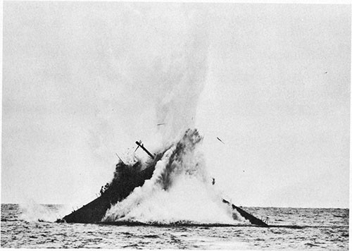
--123--
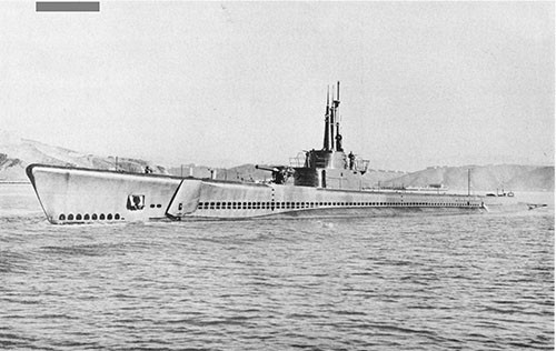
--124--
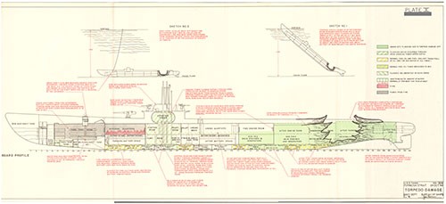
U.S.S. BERGALL (SS320)
Mine Damage
Gulf of Siam
13 June 1945
| Class | SS285 |
| Builder | Electric Boat Co., Groton, Conn. |
| Commissioned | 12 June 1944 |
| Length (Overall) | 311 ft. 9 in. |
| Beam (Extreme) | 27 ft. 3 in. |
| Submergence Depth (Designed Maximum)(Axis) | 400 ft. |
| Displacements | |
| Standard | 1525 tons |
| Emergency Diving Trim | 2050 tons |
| Submerged | 2415 tons |
| Draft (Mean, Emergency Diving Trim) | 16 ft. 10 in. |
| Type of Propulsion | Diesel Electric Reduction Drive |
| Main Engines (4) | General Motors 16-278A |
| Main Motors (4) and Generators (4) | General Electric Co. |
Reference:
(a) C.O. BERGALL conf. ltr. SS320/A16-3/A9, Serial No. 0267 of 17 June 1945 (Report of War Patrol Number
11-1. While conducting a surface search for a Japanese convoy in the Gulf of Siam on the night of 13 June 1945, during her fifth war patrol, BERGALL sustained damage to propulsion machinery as the result of an underwater detonation which occurred close aboard on her port quarter. The detonation is believed to have been caused by actuation of a proximity-fuzed mine. Propulsion power was temporarily lost and both reduction gears were damaged, although not seriously enough to render the machinery plant inoperative. As a result of the ensuing high noise level in both reduction gears, BERGALL was forced to terminate her patrol. This case is primarily of interest in that it is one of the few war damage experiences which illustrates the effect of a close underwater detonation on the Diesel propulsion plant of a U.S. submarine while running surfaced.1 In addition, it is one of the many cases which demonstrates the susceptibility of reduction gears to damage. This report is based on the information contained in the reference.
11-2. After a two-week refit by the U.S. Navy Submarine Repair Unit No. 137, BERGALL departed Freemantle, West Australia, on 12 May 1945 for her fifth war patrol. On 21 May she arrived on station in her assigned area in the waters of the Gulf of Siam. Although BERGALL covered her area thoroughly, only two contacts worthy of attack were made. The first was on 30 May when two Japanese tugs and five barges were sunk by the combined use of 20mm, 40mm and 5-inch/25 cal. gunfire at a range of about 600 yards.
11-3.The second contact was made during daylight on 12 June when a slow convoy of two small tankers and one small cargo ship, escorted by one surface vessel and one aircraft, was sighted close inshore and proceeding north. BERGALL commenced a submerged approach but range could not be closed to less than 5000 yards due to the shallow waters in which the enemy ships were operating. It was therefore decided to refrain from attacking at that time but to attempt to regain contact with the convoy after dark for a possible night surface attack.
11-4. BERGALL surfaced at 2010 that night and headed north, searching for the enemy convoy along the coast and in likely anchorage areas. Contact had not yet been regained, however, when at 0110 on 13 June, while investigating the bight in the Gulf of Siam near Kaw Luem, lat. 11° 45'N., long. 90° 50'E., a heavy detonation occurred close aboard BERGALL's port side abreast the maneuvering room. At this moment, BERGALL had just completed her search of the bay and was reversing course with left full rudder. The ship was making about 13 or 14 knots with two engines on propulsion, the shore line was less than two miles distant and the water depth was but 42 feet.
11-5. It is quite likely that the detonation was caused by a proximity-fuzed mine, inadvertently actuated by BERGALL, for this particular area had been previously mined by U.S. and British aircraft operating from bases in Asia. A subsequent check of BERGALL's track disclosed that she had run three miles inside the limits of the minefield. Seventh Fleet Submarines had not at this time been notified of the presence of Allied mines in this area. The field contained both acoustic and magnetic-
____________
1 One other such case is that of FLYING FISH (SS229) on 24 May 1944 as the result of a premature detonation of one of her own torpedoes. See brief in Appendix I.
induction ground mines of various types, with explosive charges ranging from 490 pounds to 700 pounds TPX.1
11-6. The impact of the detonation jarred the entire ship. Personnel were knocked off their feet, tossed out of bunks, and in the maneuvering room were thrown up against the overhead. Lighting failed in the maneuvering and after torpedo rooms. The overspeed trips operated on Nos. 2 and 3 main Diesel engines, which were on propulsion, and No. main Diesel engine, which was charging the batteries, causing all three engines to stop and thereby cutting off power to the main propulsion motors. The loss of load on Nos. 1, 2 and 3 generators and the jarring of the contactors for these generators in the main control cubicle caused severe arcing across the contactor tips and ignition of the leads. Severe arcing also occurred across the closed motor bus tie contactor tips in the control cubicle. Inspection disclosed that these contactor surfaces were extensively burned. The No. 4 generator reverse current relay was found to have been rendered inoperative.
11-7. Propulsion was quickly shifted to the forward and after batteries enabling the ship to get underway again within a few minutes after the detonation. Loud knocking was heard in the port reduction gear and to a lesser extent in the starboard gear. The port shaft was secured immediately to prevent possible additional damage to the port reduction gear and BERGALL proceeded to clear the area on the starboard shaft only. No enemy interference was encountered.
11-8. As stated above, when the detonation occurred, BERGALL was reversing course with full left rudder. The steering system was in power operation. Electrical power to the steering motor was lost at once due to fuzes in the motor control panel jarring out of their holders. This occurred in spite of the fact that these holders were of the improved high impact design. The casing on the lower after bearing of the port tiller ram was torn loose although the bearing itself appeared undamaged. The rudder jammed hard against its stops but after shifting to hand operation at the change valve in the control room, steering control was regained in time to steady on the desired escape course. No difficulty was experienced with the rudder in hand operation. The rudder angle indicator transmitter worm wheel was jarred out of mesh with its rack on the tiller ram and remained out of commission until repaired several hours later. In the intervening period, rudder angles were determined by the after torpedo room rudder angle indicator and relayed to the control room and bridge by sound powered telephone.
____________
1 The records of this minefield indicate that it contained a total of 6 acoustic and 28 magnetic-induction type mines. All were aircraft laid ground mines. Types and numbers of these mines were as follows:
6 - U.S. Mk. 13, Mod. 5 (Acoustic, 490 pounds TPX)
6 - U.S. Mk. 26, Mod. 1 (Magnetic, 525 pounds TPX)
3 - U.S. Mk. 36, Mod. 1 (Magnetic, 635 pounds TPX)
2 - U.S. Mk. 13, Mod. 0 (Magnetic, 700 pounds TPX)
2 - British A-Mk. V (Magnetic, 675 pounds Minol)
15 - British A-Mk. VII (Magnetic, 620 pounds Minol)
11-9. Chlorine gas was reported in the forward battery compartment immediately after the detonation and this space was promptly sealed. It was found, however, that a vinegar jug in the galley had broken and the erroneous chlorine gas report originated when the vinegar fumes were carried through the supply ventilation system to the forward battery room. The compartment was therefore opened up again.
11-10. By 0130, twenty minutes after the damage occurred, two main Diesels had been started again and put on propulsion. Both batteries were secured. Normal power operation of the steering system had been regained. BERGALL headed for the mouth of the Gulf of Siam, still using the starboard shaft only. At 0445 power was put on both shafts and speed was increased to 14 knots. The port reduction gear was very noisy at this speed but the vibration was not considered dangerous.
11-11. At 0705 BERGALL submerged, stopped the port shaft and opened the port reduction gear inspection plate. No tooth damage was apparent but the after end of the port gear casing was found to have shifted 3/16 of an inch outboard on the bedplates, the studs apparently having either been bent or sheared.
11-12. Since the noise level of the reduction gears was too high to permit submerged approach on escorted ships, and the lack of contacts to date in that area indicated little likelihood that an opportunity might present itself for a night surface attack during the few days remaining of her scheduled on-station period, BERGALL terminated the patrol and proceeded to Subic Bay, P. I., for further inspection and repairs.
11-13. With the exception of one sheared holding-down bolt outboard and aft on No. 4 main engine, and the operation under impact of the overspeed trips for Nos. 1, 2 and 3 main engines, no damage occurred to the Diesel engines proper and they performed satisfactorily until the next Navy Yard routine overhaul. The bushing on the engine air starting lever twisted loose, however, resulting in considerable loss of air (500-pound) from the air starting flasks. There was no other reported damage to equipment or systems in either of the two engine rooms. No damage occurred forward of the engine rooms with the one exception of bent slip rings on the SJ radar antenna.
11-14. In the maneuvering room, no damage occurred to the main control cubicle other than that mentioned in paragraph 11-6 above. Various minor derangements were found in this space, however, such as sheared studs, fractured welds on brackets, displacement of sheet metal bulkheads, etc.
11-15. In the motor room, a considerable leak developed around the port stern tube packing. Adapters on the lubricating oil lines were cracked at the forward bearings for main motors Nos. 1, 2 and 3 and at the after bearing of main motor No. 4. The bearing caps on Nos. 3 and 4 main motor bearings were found to have been loosened.
11-16. The dog operating mechanism of the upper hatch for the after torpedo room access trunk spun open and it is interesting to note that the holding turnbuckles, which had been installed during the previous refit, were all that prevented this hatch from opening.
11-17. Considerable damage occurred to the operating gear of the after torpedo tubes. The emergency poppet valve, for tube No. 9 jammed in the open position. The torpedo tube blow and vent manifold was jarred loose and the studs holding the vent-closing valves of the poppet system for tubes Nos. 7, 8 and 9 to the underside of the blow and vent manifold were sheared. The stop bolt rods on the four after torpedo tubes were distorted, resulting in minor leakage into the boat through the packing glands at the after trim tank bulkhead. Later inspection disclosed that three of the four after torpedo tubes were distorted to the extent that the torpedoes within had to be removed by chainfall and reloads could not be made. Both the hydrogen burning panel and the Mk. 18 torpedo charging panels were torn loose from their mountings. The track locking mechanism on one torpedo handling skid was broken. One Mk. 27 torpedo was thrown up from its stowage rack and struck the bunk above, causing a slight dent in the case of the TPX-loaded warhead.
11-18. BERGALL arrived at Subic Bay on 17 June 1945. Since investigation of the damages indicated that complete repairs were beyond the capacity of local forces, the ship was ordered to the Navy Yard, Portsmouth, N. H., where she arrived on 5 August. There complete war damage repairs together with routine overhaul and outstanding alterations were accomplished, the major item of work being repairs to the main reduction gears. Both of these gears were removed from the ship for complete inspection. On the port reduction gear, the noisiest one, it was found that the outboard pinion had been driven into the bull gear by the shock of the mine detonation. The gear assembly was considered mechanically satisfactory for it had been used during the entire 10,000-mile run to the U.S. east coast from the Philippines. However, although all points of observable impact were stoned, the high noise level in this gear could not be reduced to meet satisfactory operational requirements. It was then sent to the manufacturer for reconditioning and a new port reduction gear assembly was installed in the ship. The starboard reduction gear was found to be only slightly damaged and was returned to the ship after repairs by the Navy Yard. All work was completed and BERGALL was returned to service on 19 November 1945, about five months after the initial damage was incurred.
11-19. That BERGALL did not sustain more severe damage from the detonation was due to the fact that the mine was actuated while still at an estimated distance of between 90 and 120 feet from the hull, well outside the serious damaging-range of the mines known to have been in this field. Since both acoustic and magnetic proximity-fuzed mines are known to have been present in BERGALL's vicinity, it is not possible to determine which type of mine caused the damage.
11-20. The sensitivities of such proximity-fuzed mines are normally set for the average acoustic or magnetic characteristics of the vessels they are intended to act against so that detonation will occur when within a range calculated to cause severe or lethal damage. It is entirely possible for such mines to be swept at relatively harmless distances when the actuating influence is considerably greater than expected. For example, in the case of acoustic mines of the sonic frequency type, such as those in this field, the frequency and intensity of sound generated by submarine Diesel propulsion plants is understood to be capable of causing detonation at a considerably greater range than surface ship steam propulsion plants.
11-21. The magnetic-induction type influence mine is fuzed to detonate when the rate of change in the surrounding magnetic field exceeds a predetermined amount. This rate of change is proportional to the velocity of the ship with respect to the mine and, for a given relative velocity, will be greatest when the ship is turning through a north or south magnetic heading. Since BERGALL was reversing course at about 14 knots when the mine detonated, it is probable that her magnetic "influence" was at or near the maximum possible for that speed. It is understood that many U.S. magnetic ground mines are fuzed so sensitively that steel hulled minesweepers are not considered safe when passing overhead in less than 120 feet of water. It is not unusual for magnetic mines to detonate at distances of over 100 feet. BERGALL was ranged at Freemantle, Australia, in November 1944, at which time it was found that her signature was similar to that of an untreated and undegaussed submarine. The ship was again ranged at Pearl Harbor in July 1945, while en route to the United States shortly after the damage occurred, and her signature at this time was reported as being satisfactory for the Pearl Harbor area. Due to variation in the earth's magnetic field with latitude, however, this signature would have been 4 or 5 times greater than that of a degaussed submarine for the magnetic conditions existing in the Gulf of Siam where the mine was detonated. This would of course have greatly increased the likelihood of remote operation of a magnetic-induction type mine.
U.S.S. GRAMPUS (SS207)
Gunfire Damage
Off Truk
17 May 1942
| Class | SS198 |
| Builder | Electric Boat Co., Groton, Conn. |
| Commissioned | 23 May 1941 |
| Length (Overall) | 307 ft. 2 in. |
| Beam (Extreme) | 27 ft. 3 in. |
| Submergence Depth (Designed Maximum) (Axis) | 250 ft. |
| Displacements | |
| Standard | 1475 tons |
| Emergency Diving Trim | 1990 tons |
| Submerged | 2359 tons |
| Draft (Mean, Emergency Diving Trim) | 16 ft. 9 in. |
| Type of Propulsion | Diesel Electric Reduction Drive |
| Main Engines (4) | General Motors 16-248 |
| Main Motors (4) and Generators (4) | |
References:
(a) C.O. GRAMPUS conf. ltr. A16-3/SS207, Serial No. 04 of 17 June 1942 (Report of War Patrol Number Two).
(b) ;C.O. GRAMPUS conf. ltr. L11-1/SS207, Serial No. 05 of 30 June 1942 (Report of War Damage).
Photographs Nos. 12-1 through 12-3 (furnished by CO. GRAMPUS).
12-1. On the night of 17 May 1942, while conducting a surface patrol off Truk during her second war patrol, GRAMPUS was detected by a Japanese patrol vessel and forced to make a quick dive. While passing 30 foot depth, one shell, believed to have been a 3-inch or 4.7-inch common projectile, struck the starboard bulwark of the cigarette deck and detonated approximately three feet beyond its point of impact about two feet above the cigarette deck over the main engine air induction trunk. While no damage of a serious or military nature was caused, and GRAMPUS experienced no difficulty in subsequently evading the enemy, the action has been included in this report to illustrate the shrapnel effect of medium caliber projectiles and the obvious vulnerability of submarines to such attacks. While other U.S. submarines have been more heavily damaged by gunfire attack, this experience of GRAMPUS was chosen since it is the only such action in which photographs of the damage were available to the Bureau.
12-2. The damage report, reference (b), submitted by the Commanding Officer while the ship was undergoing repairs by OTUS (Ex-AS20) at Fremantle, W.A., is clear and comprehensive, and is therefore reproduced below in lieu of the usual narrative.
Fleet Post Office
San Francisco, California
30 June 1942
| From: | The Commanding Officer |
| To: | The Chief of the Bureau of Ships |
| Subject: | War Damage Inflicted upon U.S.S. GRAMPUS, Report of. |
| Reference: | (a) BuShips ltr. C-FS/L11-1(374); C-EN28/A2-11 of April 17 1942. |
| Enclosure: | (A) Photographs of subject damage. |
1. At 1906 (ZT) on May 17, 1942, the U.S.S. GRAMPUS surfaced on course 270° T., about twenty miles North West of the North pass to Truk Island in approximate Latitude 08° -02'-00" North and Longitude 151° -30'-00" East. This vessel had been conducting submerged patrol in assigned area. There was a moderate sea from the North East with a surface wind of about eight knots, estimated visibility 4,000 yards. At 1910 sighted a light astern that appeared to be a flash of a searchlight. At 1912 changed course to 340° T., and headed away. At 1917 echo ranging was heard on bearing 270° relative. Nothing sighted upon careful observation. At 1927 changed course to 000° T., and went to standard speed on two engines. At 1941 slowed to listen with sound gear. At 1947 simultaneously sighted and picked up with sound a vessel approximately 1500 yards on the starboard beam identified as a Japanese patrol vessel of about 500 tons. Immediately thereafter, the patrol vessel illuminated with its searchlight. The bridge was cleared and a quick dive was made to escape. At
1949 while at 30 foot depth, a sharp crack was felt in the vicinity of the bridge. The ship was checked quickly for leaks but no flooding was detected. The ship was ordered to run silently at deep submergence. At 1952 upon reaching 100 foot depth, the explosions of three depth charges were felt which were evidently close by. Between 2001 and 2005 eight depth charges were felt and screws and echo ranging heard on sound gear from three different sources. At 2044 one explosion was heard at a long range. Shortly afterwards lost contact with enemy. At 2125 surfaced on course 320° T.
2. A survey of the ship revealed that the following damage had been sustained: (1) Large shell hole approximately 4 feet in diameter in the starboard bulkhead of the cigarette deck. (2) Wooden gratings on cigarette deck splintered. (3) Cigarette deck above engine induction dished in and riddled with shrapnel holes. (4) .50 caliber machine gun mount blown off its foundation and a number of shrapnel holes in the mount. (5) Shrapnel hole about 1/2" in diameter in R.D.F. antenna loop shafting. (6) Port bulkhead and bridge structure including shelter space riddled with shrapnel leaving holes in plating varying from 3 inches in diameter to 1/4" in diameter. (7) Both after radio antennae carried away. None of the damage suffered was of a serious or military nature.
3. The best estimate of the size of the projectile used was of about 4.7" in diameter. It was evidently a high explosive shell with an instantaneous fuze. The shell pierced the bulkhead and exploded approximately three feet beyond its point of impact just above the engine induction. The fragmentation was small with a wide dispersion. The heaviest plating penetrated by the projectile and the shrapnel was 5 pound galvanized iron plate.
4. The damage was repaired by the repair force of the U.S.S. OTUS at Fremantle, W.A.
E. S. HUTCHINSON
Copies to:
COMINCH
BUORD
12-3. The damage to GRAMPUS as the result of this attack was superficial (Photos 12-1, 12-2 and 12-3) and she remained on patrol in the TRUK area until 5 June, when she departed for Fremantle, W.A., arriving on 17 June. The nature of the damage indicates that a 3 or 4.7-inch common projectile was employed. The larger Japanese anti-submarine vessels, such as frigates and large gunboats, usually were provided with one or more 12 cm./45 caliber guns(4.7-inch) with common projectiles having bursting charges ranging from 4 to 7 pounds of TNT or picric acid. Smaller anti-submarine vessels, such as the PC-13 Class, usually mounted one 8 cm./40 caliber gun (3-inch) with common projectiles having bursting charges ranging from 1 to 1.5 pounds of TNT or picric acid. Special flat-nosed anti-ricochet projectiles were frequently used by the Japanese for anti-submarine work.
12-4. Had the projectile struck a foot or so lower, or had GRAMPUS been a second or two slower in diving, serious damage would have resulted.
12-5. For other cases of gunfire damage to U.S. submarines, attention of the reader is invited to the following briefs of damage in Appendix I: SWORDFISH (SS193), 7 February 1943; SKATE (SS305), 6 October 1943; NAUTILUS (SS168), 19 November 1943: BOWFIN (SS287), 28 November 1943; ROCK (SS274). 29 February 1944; RONQUIL (SS396), 17 November 1944: BERGALL (SS320), 13 December 1944; POGY (SS266) 19 April 1945; MUSKALLUNGE (SS262), 8 August 1945.
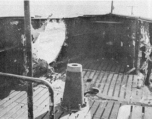
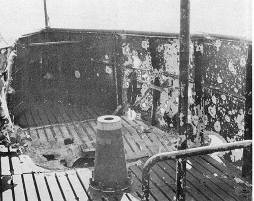
--135--
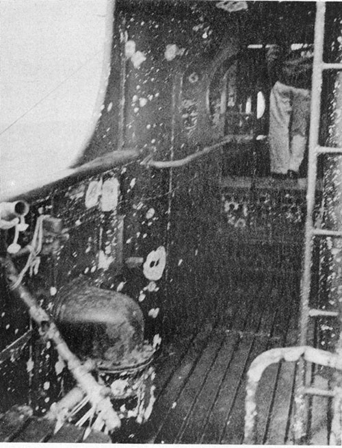
--136--
U.S.S. GROWLER (SS215)
Collision and Machine Gun Strafing Damage
Off New Britain, Bismarck Archipelago
7 February 1943
| Class | SS212 |
| Builder | Electric Boat Co., Groton, Conn. |
| Commissioned | 20 March 1942 |
| Length (Overall) | 311 ft. 9 in. |
| Beam (Extreme) | 27 ft. 3-3/4 in. |
| Submergence Depth (Designed Maximum) (Axis) | 300 ft. |
| Displacements | |
| Standard | 1525 tons |
| Emergency Diving Trim | 2050 tons |
| Submerged | 2415 tons |
| Draft (Mean, Emergency Diving Trim) | 16 ft. 10 in. |
| Type of Propulsion | Diesel Electric Reduction Drive |
| Main Engines (4) | General Motors Model 16-248 |
| Main Motors (4) and Generators (4) | General Electric Co. |
References:
(a) C.O. GROWLER conf. ltr. C-SS215/A16-3, Serial No. 0153 of 17 February 1943 (Report of War Patrol Number Four).
(b) CTF 42 conf. ltr. FF12-15(42)/A16-3/00-jm, Serial No. 057 of 18 February 1943 (Comments on CO. GROWLER Report of War Patrol Number Four).
(c) ComSubRon Eight Conf. ltr. FC5-8/S11/L11, Serial No. 054 of 25 May 1943 (Repairs to GROWLER Battle Damage).
Photographs Nos. 13-1 through 13-8 (furnished by Commander Submarine Squadron Eight).
13-1. On 7 February 1943, while on her fourth war patrol, GROWLER underwent the unique experience of ramming and possibly sinking a large enemy patrol frigate. Damage to GROWLER due to the collision and subsequent close quarter enemy machine gun fire was not sufficiently serious to prevent her from making a submerged escape and returning to base in a seaworthy condition. This report is based on the information contained in the references and on interviews with various officers attached to GROWLER. The Photographs were furnished by Commander Submarine Squadron Eight.
13-2. GROWLER arrived at Brisbane, Australia, on 10 December 1942 from her third war patrol. Normal refit was undertaken by FULTON (AS11) and completed on 31 December. On 1 January 1943 GROWLER departed Brisbane for her fourth war patrol and on 11 January reached her assigned patrol area in the waters adjacent to New Britain and New Ireland Islands in the Bismarck Archipelago.
13-3. Although many contacts were made with enemy shipping during her first few days on station, GROWLER was able to close to attack position only once. This occurred on 16 January when she sank a medium-sized freighter northwest of Watom Island with two torpedo hits during a daylight periscope attack. On 20 January GROWLER shifted her patrol area to cover the western approaches to Rabaul and on 30 January damaged a medium-sized freighter near Mussau Island by one torpedo hit during a night surface attack.
13-4. On 2 February GROWLER started patrolling toward Rabaul. On the night of 4-5 February, when south of Steffen Strait, radar contact was established with an enemy convoy and GROWLER commenced a surface chase. However, with range closed to about 5000 yards, she was detected, subjected to medium caliber gun fire and forced to submerge. Shortly afterwards, two fairly close depth charge attacks of four charges each were delivered by one of the convoy's escorts, the second of which partially blew out the gasket to the No. 1 MBT boiler type manhole cover in the deck of the forward torpedo room.
13-5. Water entered in considerable volume through this opening but not in sufficient quantity to seriously affect depth control and GROWLER managed to lose the enemy escorts about one-half hour later. The leak grew steadily worse, however, and by one hour after the initial attack, water was entering the forward torpedo room at an estimated rate of over 1000 gallons per hour. The drain pump was run continuously on the torpedo room bilges and this sufficed to keep the water level within the compartment under control. An effort was also made to close off the manhole by using a sheet rubber gasket backed by deck plates held in place by shores and two jacks. This measure did not stop the leak but was reported to have prevented it from becoming more serious. Surfacing during daylight hours for repairs was not considered feasible due to the close proximity of the searching enemy anti-submarine vessels and, although diving trim control was poor, GROWLER remained submerged. Upon surfacing after dark, repairs were quickly effected by placing the forward
torpedo room under 7 pounds per square inch air pressure and renewing the manhole gasket. A test dive was then made and the new gasket was found to be satisfactory.1
13-6. During 5-6 February GROWLER remained on submerged patrol off Watom Island. At 2200 6 February orders were received to shift station and GROWLER proceeded to her new area on the surface at 17 knots. At 0110 7 February, while in a position about 50 miles off the northwestern end of New Britain Island, lat. 3° 34'S., long. 151° 09'E., GROWLER established contact with a large Japanese converted patrol frigate. Visibility was poor and limited to about 2000 yards. The enemy ship was just barely discernible off the starboard bow and was proceeding on opposite course. GROWLER immediately turned away, made her tubes ready and then headed directly toward the frigate for a surface torpedo attack.
13-7. When GROWLER was almost in firing position, with radar range of 2000 yards and track angle 130° starboard to the target, the enemy frigate sighted her, immediately reversed course and closed to make a counterattack. This maneuver was apparently not immediately discerned by the bridge on GROWLER although the fire control party in the conning tower is reported to have given accurate radar ranges and to have had the TDC solution. At 0134, after range to the enemy vessel as indicated by TDC track and radar was too close to permit torpedo fire, the bridge gave the order "Left full rudder" and sounded the collision alarm. At 0135, while swinging with left rudder and at speed 17 knots, GROWLER rammed the enemy frigate head on, striking midway between her bow and bridge.
13-8. The impact of collision was terrific, heeling GROWLER to about 50 degrees and knocking most of the crew off their feet. Immediately afterwards, the enemy opened fire on GROWLER's bridge with one or more 13mm machine guns2 at point blank range and on GROWLER the order was given "Clear the bridge". Four of the seven men present on the bridge descended into the conning tower. Two of these men were wounded and had to be helped through the upper hatch. After approximately 30 seconds had elapsed since the last man had come below and still no one else had appeared at the hatch, the diving alarm was sounded, upper conning tower hatch was secured and GROWLER submerged. The enemy continued strafing the bridge with machine gun fire until it was under water. It is believed that the three men remaining topside, the Commanding Officer, the assistant Officer of the Deck and a lookout, were killed or seriously wounded by the enemy fire before GROWLER submerged and for that reason were unable to clear the bridge.
____________
1 As a result of GROWLER's experience and reports of similar casualties from other submarines, the Bureau authorized by ShipAlt SS167 of 12 March 1943 the replacement with welded blanks of the forward and after ballast tank boiler type manhole covers as installed in the torpedo room decks on SS175-284. On SS285 and subsequent submarines, such ballast tank accesses were omitted from the design.
2 Recovered projectiles were measured and found to be 13mm.
13-9. Damage to GROWLER can be conveniently divided into two categories: (a) damage due to the collision and (b) damage due either directly or indirectly to the enemy machine gun fire. Damage due to collision was limited to the extreme forward portion of the ship. The entire bow structure forward of frame 10, a length of about 25 feet, was either crumpled or considerably distorted and forward of frame 4 was bent about 90 degrees to port (Photos 13-1 and 13-2). This structure consists only of the relatively light plating and framing of the bow buoyancy tank (10-pound MS). Deck plating back to frame 12 was wrinkled and torn. Bulkhead No. 10 was dished in only about 3/4 inch at the centerline in way of the torpedo tube nest but above the tubes was distorted somewhat more extensively (Photo 13-3). Grease lines, bow buoyancy tank vent valves and operating gear, and the torpedo tube shutters and operating gear were completely wrecked. On subsequent docking, it was found that No. 3 torpedo tube shutter had jammed into No. 3 tube outer door gasket groove but that no damage had occurred to any of the forward torpedo tubes proper. The bow planes operated without difficulty and were undamaged with the exception of slight misalignment of the tilting shaft. Depth control was reported as being somewhat difficult after the collision and during the return trip to base. This is attributable to the protruding structure of the damaged bow (Photos 13-1 and 13-2) which acted as both a fixed plane and "plow" at maximum lever-arm distance from the turning center of the boat and also blanked off normal flow of water to the port bow plane, thereby considerably altering its planing effect.
13-10. Direct materiel damage due to the enemy machine gun fire was in itself relatively minor but the indirect damage caused by resultant flooding became quite serious. Although the bridge and conning tower fairwater were hit in numerous places1 (Photo 13-4), fortunately only one projectile pierced the pressure hull. This penetrated the bronze upper conning tower hatch while it was in the open position prior to diving and tore a hole about 1/2 inch wide and 3/4 inch long (Photo 13-5). Two other projectiles struck the No. 1 periscope shear pipe structure in the bridge "covered wagon", jamming the periscope so that it could neither be trained, raised or lowered but caused no damage to the periscope tube itself (Photo 13-6). Electrical cables on the bridge for the collision alarm, IMG, sidelights, target bearing transmitters and bridge steering repeaters were shot away. On submerging, water entered the conning tower in large volume through the sheathing of these punctured cables2 in addition to the hatch bullet hole. Although the leaks were observed as soon as GROWLER's conning tower went under, no attempt was made to surface due to the presence of the enemy vessel above nor was the conning tower abandoned. Efforts were made to plug the leaks but were largely unsuccessful. Depth was maintained at 150 feet in spite of the flooding and the subsequent detonations of two depth charges which were not close and did no damage.
____________
1 The conning tower fairwater and bridge plating on GROWLER were but 5-pound and 7-1/2 pound weight MS. As a result of this and other actions, the installation of 25-pound and 30-pound STS plating for the protection of bridge personnel was authorized by ShipAlt SS177 of 16 April 1943 for all fleet type submarines subsequent to SS197.
2 For further discussion of cable sheathing leaks, see paragraph 19-12.
13-14. GROWLER made the return trip back to base by running submerged during daylight hours while in enemy patrolled waters and running surfaced at night. She arrived alongside FULTON (AS11) at Brisbane, Australia, on 17 February 1943.
13-15. After a survey of the damage it was considered both possible and desirable to undertake complete repairs with local facilities, provided damage to the forward torpedo tubes was not extensive. A drydock examination disclosed that the tubes were undamaged and in correct alignment, with the exception of the previously mentioned damage to muzzle door operating gear and shutters. The Evans Deakin Company of Brisbane undertook replacement of the damaged bow structure, prefabricating and installing the new bow in two horizontal sections (Photo 13-7). Fittings were salvaged from the damaged structure where possible. The work was accomplished in the Moreton graving dock, Brisbane. FULTON undertook all other battle damage repairs and in addition gave the ship a regular refit. All work was completed and GROWLER was returned to service on 4 May 1943.
13-16. GROWLER's experience illustrates that, should the tactical situation so require, it is possible for modern fleet type submarines to successfully ram light-hulled vessels such as destroyers or patrol craft without necessarily destroying their own watertight integrity, seaworthiness and ability to conduct submerged operations.1 This is principally attributable to the 30 odd feet of non-watertight bow structure ahead of the forwardmost pressure hull bulkheads, in this case the forward and after bulkheads of the forward trim tank. This bow structure effectively cushions collision shock by absorbing the damage in a non-vital area while depleting the relative momentum of the two ships involved, and tends to prevent serious injury to pressure hull structure farther aft.
13-17. GROWLER's experience also demonstrates the extreme vulnerability of unarmored submarines, when surfaced, to even small caliber projectiles, as from aircraft strafing or light machine gun fire from surface vessels. It was fortunate for GROWLER that the enemy machine gun fire was directed at her bridge instead of her pressure hull or conning tower. Had the latter been the case, the resulting numerous small holes might have prevented GROWLER from
____________
1 Another excellent example is the collision between ARGONAUT (SS475) and HONOLULU (CL48) on 8 January 1946 off the U.S. east coast. The angle of collision was about 30 degrees, ARGONAUT's bow striking about 75 feet aft of the stem on HONOLULU's starboard bow. Although both ships started backing down just prior to the collision, the relative speed of the two ships at the instant of initial contact is believed to have been in excess of 20 knots. Damage to ARGONAUT was very similar to but more severe than that which occurred to GROWLER. The bow forward of frame 11 was completely crumpled and bent 90 degrees to starboard. Minor damage was sustained to plating, framing and the vertical keel between frames 11 and 16 (MBT No. 1) but no damage occurred to the forwardmost pressure bulkhead at frame 16. The outboard and intermediate sections of all forward torpedo tubes were bent to starboard. No internal flooding whatever occurred on ARGONAUT and she remained seaworthy and could have submerged had the occasion required.
making a submerged escape after the ramming and in that case the enemy frigate very probably would have completed her destruction. Even presuming GROWLER were to escape the enemy ship on the surface, multiple small holes in the pressure hull and external tanks might still have caused her loss, either by direct flooding or by preventing submergence if again attacked while making the surface run back to base through enemy controlled waters. Ballistic data shows that U.S. 50 caliber AP (M2) and Japanese 13mm AP projectiles, when fired from within 500 yards range at 0° obliquity, will penetrate both the outer and inner hull of a submarine, assuming the plating to be 3/8-inch and 7/8-inch medium and high tensile steel, respectively. Even when fired at 30° obliquity, and assuming the projectiles tumble after penetrating the outer hull so as to strike the inner hull lengthwise, the 50 caliber and 13mm AP projectiles will pierce both hulls within a range of at least 100 yards.
13-18. After completing six more patrols, GROWLER was lost in action with all hands on 8 November 1944 while attacking a Japanese convoy in the central Philippines area during her eleventh patrol. Information furnished by HAKE (SS256) and HARDHEAD (SS365), both of whom were operating with GROWLER at the time, indicates that the loss possibly occurred either as a result of enemy depth charging or the malfunctioning of one of GROWLER's own torpedoes. During her first ten patrols GROWLER sank 17 ships for a total tonnage of 74,900, and damaged 7 ships for 34,100 tons.
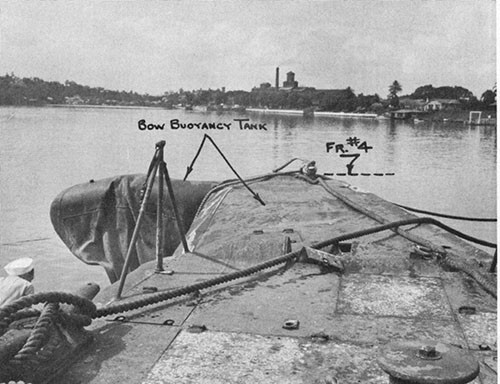
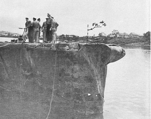
--144--
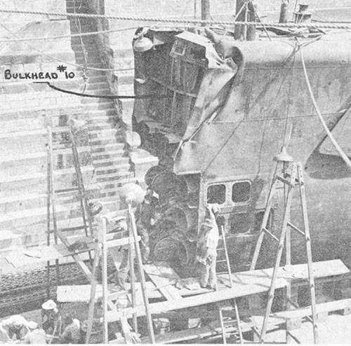
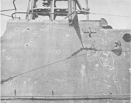
--145--
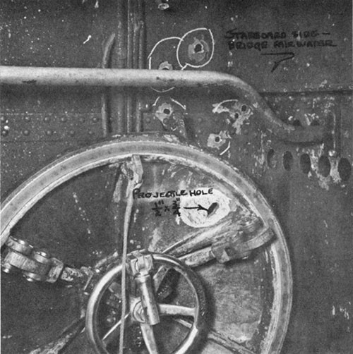
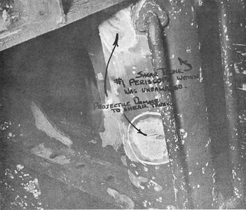
--146--
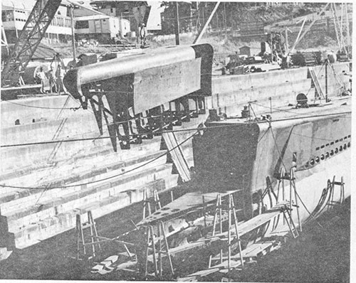
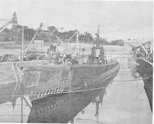
--147--
U.S.S. DRAGONET (SS293)
Grounding While Submerged
Off Matsuwa To, Kurile Islands
15 December 1944
| Class | SS285 |
| Builder | Cramp Shipbuilding Co., Philadelphia, Pa. |
| Commissioned | 6 March 1944 |
| Length (Overall) | 311 ft. 8 in. |
| Beam (Extreme) | 27 ft. 3-1/4 in. |
| Submergence Depth (Designed Maximum) (Axis) | 400 ft. |
| Displacements | |
| Standard | 1525 tons |
| Emergency Diving Trim | 2050 tons |
| Submerged | 2414 tons |
| Draft (Mean, Emergency Diving Trim) | 16 ft. 10 in. |
| Type of Propulsion | Diesel Electric Reduction Drive |
| Main Engines (4) | Fairbanks-Morse 38-D-8-1/8 |
| Main Motors (4) | Elliott Co. |
| Main Generators (4) | General Electric Co. |
References:
(a) C.O. DRAGONET conf. ltr. SS293/A16 of 20 December 1944 (Report of War Patrol Number One).
(b) CO. DRAGONET secret ltr. SS293/A2-11/L11-1, Serial No. 1 of 26 December 1944 (Report of Damage Due to Grounding).
(c) Comdt.Navy Yard Mare Island conf. ltr. SS293/S11-1(360-718391) of 19 March 1945 (Supplementary Report on DRAGONET Grounding Damage).
Photographs Nos. 14-1 through 14-8 (furnished by Navy Yard, Mare Island).
PLATE XIV
14-1. On 15 December 1944, during her first war patrol, DRAGONET holed and flooded her forward torpedo room as a result of striking an uncharted reef while running submerged off the Kurile Islands, and sank to the bottom in about 90 feet of water. DRAGONET was able to surface only after expelling the water from the torpedo room with salvage air, and she made the run back to base, through heavy weather, by continuing to maintain an air bubble in the damaged compartment. Although this case cannot be said to have resulted directly from enemy action, it has been included in this collection of war damage experiences to illustrate the problem of a submarine having one end compartment flooded while submerged. It is considered quite possible that other and less fortunate U.S. submarines during World War II may have received damage from enemy action, mines, ramming or grounding, which resulted in the flooding of an end compartment, and that the loss of these vessels may have been caused thereby. This report is based on the information contained in the references and on an informal interview with the then Commanding Officer. The Photographs were furnished by Navy Yard, Mare Island. The PLATE was prepared by this Bureau from data contained in the enclosures to reference (c).
14-2. On 9 November 1944, DRAGONET departed Midway for her first war patrol and on 17 November reached her assigned patrol area in the Sea of Okhotsk and along the Kurile Islands chain. For the next 28 days, until the grounding on 15 December, DRAGONET searched her area thoroughly but no enemy ship contacts worthy of torpedo fire were made. Weather conditions were extremely adverse during this period and strong currents and tide rips were experienced when operating close offshore or between islands.
14-3. During the early morning hours of 15 December, DRAGONET was conducting a surface patrol in an area slightly to eastward of the Kuriles chain. It was planned to submerge at daylight at a point about five miles south of the town of Yamato Wan on the east coast of the Island of Matsuwa To and to patrol across the southern approaches to this anchorage. Study of available hydrographic information indicated that navigational hazards in this area existed only close inshore. At 0515 DRAGONET submerged in Rashowa Strait to a depth of 100 feet in order to trim the boat. Although the sea was flat calm there were pronounced tide rips which rendered depth control difficult.
14-4. At 0717, in a position six miles south of Matsuwa To, DRAGONET was returning to a depth of 100 feet after a periscope observation at 63 feet, and had reached a depth of 70 feet, when a slight jar forward was felt. At this time the boat was running counter to the current in Rashowa Strait on course 090° (T) and had just rung up a change from one-third speed (1-1/2 knots) to two-thirds speed (4 knots). When the jar occurred, the ship had probably reached a speed of only about 3 knots and since observations had indicated that the current was about 2 knots, DRAGONET was probably making only about 1 knot over the ground. A dive angle of about two degrees was being carried. Immediately after receiving the jar forward, the boat assumed a three degree up angle and started to rise.
14-5. The first reaction on DRAGONET was that a plane or small patrol craft, not seen by periscope, had located the boat and was dropping depth bombs or charges. Reference (b) states that "the feeling was much the same as experienced during depth charging when explosions are not very close". Enemy aircraft bombing was entirely possible, for visibility was unlimited, flying conditions were excellent and DRAGONET was only about 12,000 yards distant from a known seaplane base on Matsuwa To. Available information also indicated that there might be a military air base on the southeast side of the Island.
14-6. Following this reasoning, it was decided to seek safety in depth as quickly as possible and by the time the boat had risen to 58 feet, the negative tank was flooded, a two degree dive angle was ordered and emergency speed was rung up. These actions enabled the boat to gain depth rapidly but when 90 feet was reached, only 10 or 15 seconds after receiving the first slight jar forward, a series of heavy jolts accompanied by loud noises shook the entire boat and caused it to lurch violently. DRAGONET's speed at this time is estimated to have been about 6 or 7 knots by shaft turns, or about 4 or 5 knots relative to the bottom. This second and violent jolting was also at first interpreted as another depth charge or bombing attack and orders were issued to proceed to 150 feet and rig the ship for depth charge. Almost immediately afterwards, however, it was noticed that the boat was hanging at a depth of 92 feet with a dive angle of 20 degrees, the log recorded zero speed, and further jars occurred forward accompanied by loud grinding sounds. It was then realized that the boat had gone aground on a submerged reef or pinnacle and both shafts were stopped at once. The ship had no appreciable list at this time.
14-7. At about 0718, directly after the second grounding had occurred, word was received in the control room that the forward torpedo room was flooding rapidly (PLATE XIV). The collision alarm was sounded and the forward torpedo room was ordered abandoned. Only four members of the crew were present in that space and they promptly retired to the forward battery compartment. A watertight boundary was immediately established at the after bulkhead of the forward torpedo room by closing the bulkhead door and the bulkhead supply and exhaust ventilation flapper valves. Salvage air (225-pound) was then bled into the torpedo room through the bulkhead connection in an effort to halt the flooding, but was secured when the pressure within the compartment had reached about 55 pounds per square inch. Shortly afterwards, word was received in the control room that the torpedo room was "completely flooded". Complete flooding could not have occurred, however, since the rupture in the compartment was just above the watertight deck flat, allowing air to be entrapped in the overhead, and it is presumed that this report was made after the water passed over the top of the sight glass in the bulkhead watertight door. Later inspection disclosed that the water level in the compartment reached a height of about 1 foot above the upper bunks, or about 1-1/2 feet below the overhead of the torpedo room. Since a clock located just below the maximum flood line in the torpedo room stopped at 0720, it appears reasonable to assume that flooding of that space took place in approximately two minutes or less.
14-8. As DRAGONET was pounding violently and lurching with the surge of the current at this time, it was feared that further serious damage would be sustained and that the hull might possibly break up unless the ship were quickly taken off the rocks. Word was passed to all hands to obtain objects that would float in case the boat might have to be abandoned. At about 0721, 3 minutes after the grounding occurred, the first attempt was made to get off the bottom. All main ballast tanks were blown plus bow buoyancy, negative and safety tanks. Nos. 3, 4 and 5 fuel ballast tanks were empty of oil but due to unfavorable sea conditions had not yet been converted to main ballast tanks by removing the riser blanks, and therefore were not blown since subsequent rapid venting, if the boat were required to again submerge, would have been impossible.
14-9. The increase in buoyancy resulting from the blowing of the main ballast tanks caused the stern of the boat to rise to the surface but the bow remained either on or near the bottom, due to the flooded compartment forward.1 When the stern rose, it acquired sufficient momentum to considerably overshoot its point of static buoyancy and surged out of the water far enough to project the extended No. 2 periscope above the surface for a second or two. The Commanding Officer had time only to make a partial sweep to port, but this brief observation disclosed that all was clear in the direction of Matsuwa To. The stern then settled back in the water until it reached its equilibrium point for the static buoyancy condition, the boat assuming a down angle of about 30 degrees. Since both periscopes went under the surface, no further observations could be taken.
14-10. As the stern was protruding out of water and therefore might be sighted by the enemy, and the bow could still not be raised due to the loss of buoyancy forward, all tanks were again flooded to submerge the ship. This action was taken at about 0730. DRAGONET once more settled to the bottom, in a depth of about 92 feet and with a 16 degree down angle. The ship's heading had now swung from 090° (T) to 110° (T) and the action of the current once again caused DRAGONET to pound heavily on the reef. It was thought at this time that perhaps the bow had been prevented from rising by being wedged in the rocks, so a brief attempt was made to back clear of the reef using emergency power. This proved unsuccessful, however, and the plan was abandoned.
14-11. At 0732 a report was received that the 55-pound per square inch air pressure which had originally been built up in the forward torpedo room had now diminished to 40 pounds and that the water in that compartment was below the eyeport in the bulkhead door and continuing to recede. A few minutes later, air could he heard blowing outside the torpedo room hull, indicating that the water level in the compartment had been lowered to the point of rupture and the down angle on the boat began to decrease slowly. The order was then given to blow the forward main ballast tank group, bow buoyancy, safety and negative tanks. As this caused the ship to trim by the stern, the after group of main ballast tanks was then blown. The ship rose slowly and surfaced at 0738, in clear sight of the shore establishments on Matsuwa To. When 26 feet was reached, the upper conning tower hatch was opened and the tanks were then blown with the low pressure (10-pound) air system as in any normal surfacing.
____________
1 For further discussion see paragraph 17-16.
14-12. All four main engines were started immediately and the area was cleared as rapidly as possible by proceeding south at emergency speed. All automatic weapons were manned and ammunition was broken out. Fortunately, no enemy interference was experienced as DRAGONET retired. Course was then set for Midway, the nearest Allied base.
14-13. The boat was only slightly down by the head on surfacing but was reported to have assumed about 15 degrees port list, for ruptures in the outer plating of port MBT Nos. 6B and 6D prevented those tanks from being blown below a few feet from the tank tops. Steps were taken immediately to increase freeboard, to reduce trim by the head and to correct the excessive list. Flood valves on Nos. 3, 4 and 5 fuel ballast tanks, both port and starboard, were opened and these tanks were blown in order to increase freeboard. MBT No. 6A and FBT No. 3A on the starboard side were then made free-flooding to compensate for the 15 degree port list. All variable tanks were pumped dry with the exception of No. 3 auxiliary, which was flooded as an additional list correction, and after trim tank, which was left about 3/4 full in order to add weight aft. No. 6 normal fuel oil tank was put on service to add weight aft by displacing fuel oil with heavier sea water. Air pressure was maintained on the forward torpedo room through the salvage air system and this kept the water within the damaged compartment at a low level. The after bulkhead of the torpedo room held tight with the exception of a few minor electrical cable stuffing gland leaks.
14-14. Heavy seas and high winds built up on 16 December. The bow planes were still rigged out and pounded so heavily that the entire ship vibrated and it was feared that further serious hull damage forward might result. A slight air leak developed around the top of the bulkhead door to the forward torpedo room but did not become serious. One of the bulkhead cable packing gland leaks increased somewhat, allowing water to enter the pantry. The gland nut was located in such a position that it was inaccessible and could not be tightened. When the grounding occurred and the forward torpedo room flooded, the Mk. 18 electric torpedoes in tubes Nos. 1 and 4 were in a partially withdrawn position for charging. Consequently, the inner doors of these tubes were open and the outer doors were closed but not locked. As the water level in the torpedo room was noted to be rising during this period of heavy weather, and salvage air had to be used in increasing quantities to maintain the air bubble in the torpedo room, it was believed that air must be leaking through one or both of the torpedo tube outer doors. Both high pressure air compressors had to be run continuously to provide sufficient salvage air. The three air banks on service were never allowed to drop below 2500 pounds pressure while the two emergency banks were kept at full pressure.
14-15. By 1800, the storm had increased in intensity. In order to decrease the draft forward and, therefore, the water level in the torpedo room, the contents of NFO tank No. 1 were blown aft into FBT Nos. 5A and 5B. During this transfer, DRAGONET developed a 20 degree port list, indicating that most of the water and oil in NFO No. 1 had ended up in FBT No. 5B, the port tank. The list shortly
decreased to about 10 degrees but the ship commenced to roll heavily, reaching a maximum of 40 degrees to port. Compensation was accomplished by opening the floods of FBT No. 5B and blowing its contents to sea but this apparently over-corrected the list, for No. 3 auxiliary tank was then pumped dry.
14-16. By morning of 17 December the seas had abated somewhat, the bow was riding higher and the water in the forward torpedo room was down to about 12 inches above the floor plates and appeared to be maintaining this level. However, the bow planes were still pounding heavily. It was therefore decided to attempt to enter the forward torpedo room to rig in the planes, tighten up the torpedo tube outer doors and to determine the extent of damage.
14-17. A party of three officers and two men entered and secured the forward battery compartment. Rescue breathing equipment and "lungs" were carried in case chlorine gas might be generated should sea water inadvertently enter the battery cells from the forward torpedo room. Air pressure was built up in the battery compartment by the salvage air system and the control room bulkhead was then inspected and found tight. The small line to the salvage air gauge for the torpedo room was then disconnected in order to equalize the pressure between the two forward compartments. Bulkhead flapper valves in the hull ventilation system were not opened to accomplish this for fear they could not be securely closed again. When the pressure between the compartments had equalized, the bulkhead door was opened and the party entered the forward torpedo room. As the water level in that compartment was well below the bulkhead door, no water entered the battery compartment and the rescue breathers and "lungs" were discarded. By working in relays, the bow planes were rigged in by hand and the torpedo tubes were secured. The air in the torpedo room was foul with oil fumes so oxygen was bled into the compartment to improve working conditions.1 When the bow rose in the seaway, daylight could be seen through a ruptured area in the pressure hull plating, centered at frame 23, port side, just above the top of the forward trim tank. This was the first positive information that any of ship's company had as to the nature of the damage causing the flooding. Upon completion of the work, the torpedo room was again abandoned and sealed, and the air in the forward battery compartment was bled into the control room. The success of this well-executed and potentially hazardous operation for the safety of the ship removed many of DRAGONET's difficulties. The bow planes were subsequently further secured by running chains through the rigging gear quadrants in the superstructure.
14-18. Heavy seas and winds of gale force were again encountered late in the evening of 17 December and continued until the afternoon of the next day. At 0245 on 18 December, with the seas approaching from the starboard quarter, DRAGONET took a very large roll to port and "hung"
____________
1 The introduction of pure oxygen into a compartment containing strong petroleum vapors is a potentially dangerous expedient, for it may result in an explosive mixture which will ignite upon the introduction of a spark or open flame. The safest procedure in a case of this nature is to don rescue breathers or "lungs" when oil fumes become objectionable.
at an extreme angle for an appreciable period of time. This roll was measured on the clinometer in the control room as 63 degrees.1 Men were thrown from bunks and mercury spilled from the flotation chamber of the master gyrocompass, completely disabling it. Seas filled the port side of the bridge, but fortunately did not reach the upper conning tower hatch. The rudder was put at full left and the ship's heading was swung through 105 degrees before the ship slowly came back to about 20 degrees port. list. When MBT No. 6A and FBT No. 3A were vented, the ship came upright again, indicating that the flood openings of these tanks may have become exposed by the coincidence of a deep wave trough at the extreme roll, allowing the water within to escape and causing air pockets to form. Both MBT No. 6A and FBT No. 3A had been previously flooded to compensate for the port list which DRAGONET had assumed on surfacing.
14-19. DRAGONET arrived at Midway on 20 December 1944 and was docked the same day in ARD8 for inspection and emergency repairs. Temporary patches were installed over the holes in the forward torpedo room pressure hull and the outer plating of MBT Nos. 2B, 6B and 6D. The ship departed Midway on 23 December for Navy Yard, Mare Island, and arrived on 4 January 1945. Complete repairs together with many outstanding alterations were accomplished there and DRAGONET was returned to service on 26 March 1945.
14-20. Structural damage due to grounding was found to have occurred in five different areas along the hull, these being designated hereinafter as damages "A", "B", "C", "D", and "E". The location and nature of each damage is shown in PLATE XIV and Photos 14-1 through 14-8. PLATE XIV also indicates the extent of structural replacements in way of the damaged areas which were accomplished by Navy Yard, Mare Island, to effect permanent repairs. It should be noted that all of the structural damage areas, with the exception of damage "A" and "B" at the bow, occurred along the port side of the ship at about maximum beam of the ship at each point and that no damage was sustained by the keel or adjacent structure. This indicates that the ocean floor itself was soft and that the damage was caused by DRAGONET striking the horizontal promontories of an outcropping of rock.
14-21. In connection with damage at "B" (Photos 14-1, 14-2, and 14-3). it was at first believed that the lower torpedo tubes, and possibly the entire nest of tubes, were out of line. However, when the ship was docked at Mare Island, bore gaging and a careful inspection disclosed that no damage or misalignment of the tubes had occurred. The damage at "C" to the single (pressure) hull plating (37.5-pound HTS) caused the flooding of the forward torpedo room (Photos 14-1, 14-4, and 14-5). Since that compartment was flooded for several days, most of the electrical equipment within had to be replaced and all of the ordnance gear had to be overhauled. Damage at "D" (Photo 14-6) was extensive to outer shell plating but no deformation occurred in the inner hull. The outer hull was breached in only one place in this area, a 12-inch crack at frame 49 below the bilge keel (Photo 14-7) in way of MBT No. 2B. The damage at "E" (Photo 14-8) ruptured the outer shell plating of MBT Nos. 6B and 6D at about the mid-height of each tank. Since these tanks could be blown down only
____________
1 For further discussion see paragraph 17-7.
to the point of rupture, the resulting off-center water loading caused the ship to assume a port list upon surfacing.
14-22. The 37.5-pound HTS shell plating of the forward torpedo room, which was ruptured over a wide area as a result of the grounding, (damage "C"), was cut out of the ship in one section (Photo 14-4) and sent to the Industrial Laboratory of the Navy Yard, Mare Island, for examination and testing. The mode of fracture (Photo 14-5) had suggested that possibly this plating on DRAGONET possessed insufficient ductility or other undesirable qualities. Physical tests and chemical analysis on seven HTS samples from the damaged area, however, indicated that all complied with the requirements of Navy Department Specifications 48-S5-(INT). Although the granular appearance of the torn edges suggested that the crystalline structure of the HTS plating might have been large, a comparison with another specimen of known quality demonstrated that the damaged HTS was similar to that in general use. It appears, therefore, that the material was sound and failed as a result of heavy concentrated loading when that area of the hull struck a rocky promontory, although the low temperature of the water, 29° F., may have been a contributing factor. 1
14-23. DRAGONET's experience illustrates several pertinent matters. First, the great value of the internal salvage air system as fitted in U.S. submarines was once again demonstrated. Second, the damage which occurred to DRAGONET represents the best available example of what should be expected when a modern heavy-hulled submarine grounds forward on a hard reef while running submerged at low speed. With the trend in submarine design now tending toward increased operating depths and higher submerged speeds, it is considered likely that more instances of this nature will occur in the future. Third, this case clearly demonstrates the fact that a submarine on the bottom, with an end compartment flooded, can be brought to the surface in a horizontal attitude only if the longitudinal center of buoyancy resulting from tank blowing is very close to the longitudinal center of gravity. If this condition is not satisfied, only the light end will rise and the ship will assume a spar buoy position, as was the case with DRAGONET on her first attempt to surface. The most obvious method of longitudinally balancing a submarine in such cases is to eject that water which is responsible for the off-balance condition by any means available, usually the salvage air system. This was the method used by DRAGONET which permitted her to surface on her second attempt. If dewatering is found impossible, then longitudinal moment balance may be achieved by flooding the compartment at the opposite end of the ship and/or by flooding and blowing only such a combination of internal and external tanks as will offset the moment of the originally flooded compartment and yet provide the maximum reserve buoyancy possible. On DRAGONET,
____________
1 For further discussion see paragraph 16-25.
for example, if all external tanks aft of and including the No. 6 MBT groups had been left flooded and the after trim tank and after WRT were completely filled, the ship could then have been surfaced, even though the torpedo room was completely flooded, by blowing the amidships and forward MBT, FBT and variable tanks. This loading would have resulted in a reserve buoyancy after surfacing of about 300 tons, or only about 50 tons less than the emergency diving trim condition. It should be noted that normal fuel oil tanks are also available for blowing should such be considered desirable or necessary to achieve longitudinal moment balance.
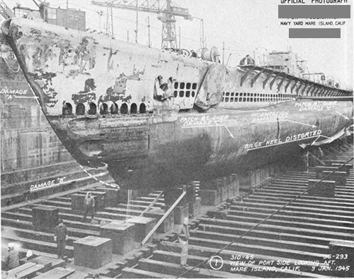
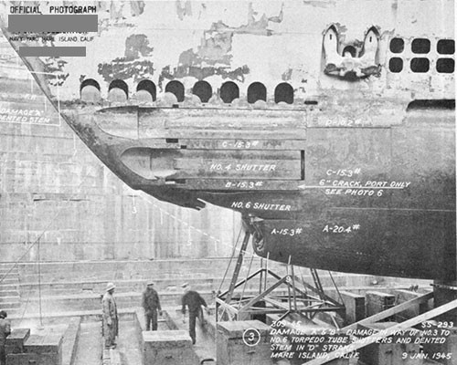
--157--
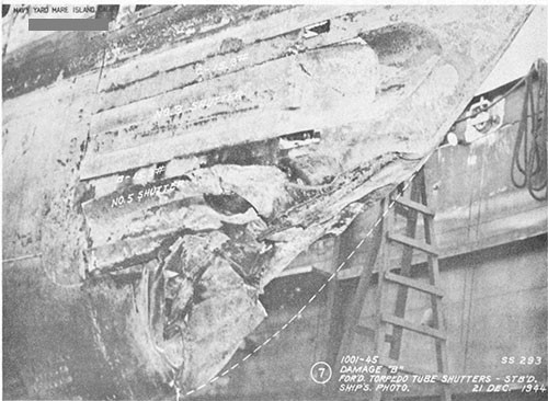
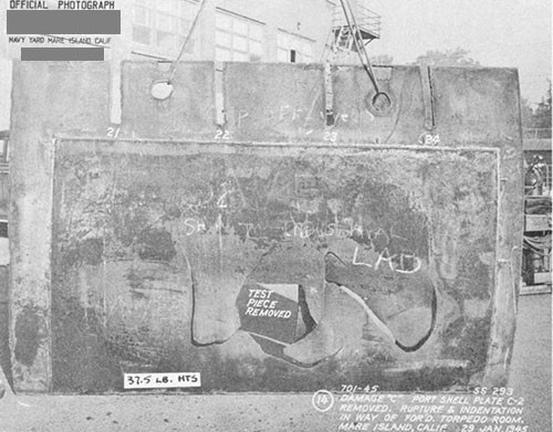
--158--
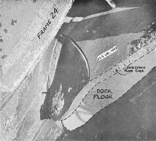
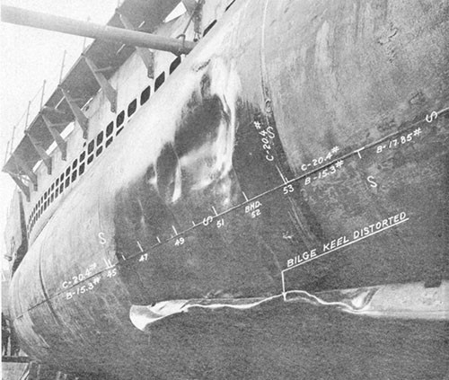
--159--
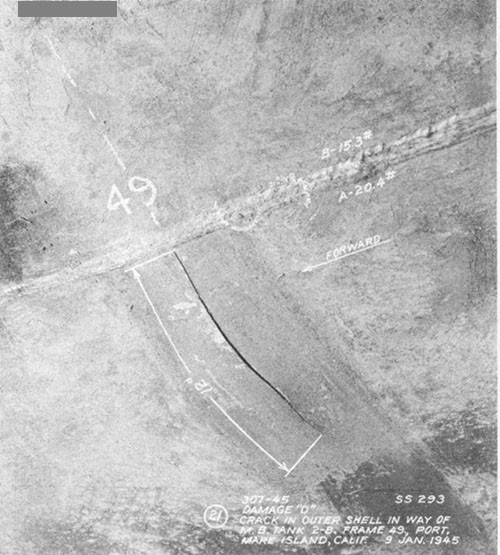
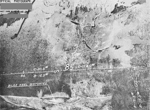
--160--
