The Navy Department Library
USS Independence (CVL22) & USS Denver (CL58) Torpedo Damage
Tarawa 20 November 1943 & Treasury Islands 13 November 1943
NAVSHIPS 52 (424)
CONFIDENTIAL
U.S.S. Independence (CVL22)
Torpedo Damage
Tarawa
20 November, 1943
U.S.S. Denver (CL58)
Torpedo Damage
Treasury Islands
13 November, 1943
The Commander-in-Chief, United States Fleet and Chief of Naval Operations directs that this report be shown only to those persons to whom the report would be of value in the performance of their duties.
Steps shall be taken accordingly to insure that the report will be seen by those persons responsible for design, construction and repair of naval vessels, as well as for their operation, but by no others.
Preliminary Design Section
Bureau of Ships
Navy Department
10 July, 1945
WAR DAMAGE REPORT No. 52
Printed By U. S. Hydrographic Office
CONTENTS
| Section | Page | |
| I | Foreword | 1 |
| II | Summary | 1 - 3 |
| A. INDEPENDENCE | ||
| B. DENVER | ||
| III | Narrative | 4 - 15 |
| A. INDEPENDENCE | ||
| B. DENVER | ||
| IV | Discussion | |
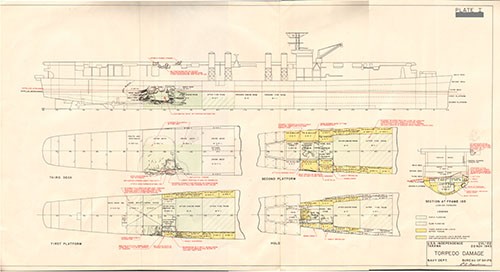
| A. Types of Torpedoes | 15 | |
| B. Structural Damage | 15 - 16 | |
| C. Engineering Comments | 16 - 20 | |
| D. Notes on Miscellaneous Matters | 20-21 | |
| E. Ammunition Behavior | 21 - 22 | |
| F. Flooding and Stability | 22 - 23 | |
| G. Damage Control Notes | 23 - 24 | |
| H. Conclusion | 24 |
LIST OF PLATES
I Torpedo Damage and Flooding - INDEPENDENCE
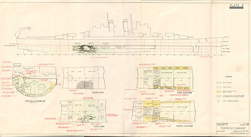
II Torpedo Damage and Flooding - DENVER
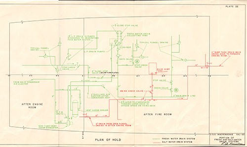
III Portion of Fresh and Salt Water Drain Systems - INDEPENDENCE
--i--
U.S.S. INDEPENDENCE (CVL22)
| Class | Aircraft Carrier (Small) (CVL22 Class) | Length (O.A.) | 610 ft. |
| Launched | 22 August 1942 | Beam (Extreme) | 71 ft. 6 in. |
| Displacement (Standard) | 11,000 Tons | Draft (Before Damage) | 23 ft. 6 in. |
References:
(a) C.O. INDEPENDENCE ltr. CVL22/A16-3, Serial 0010 of 25 November 1943 (Record of Events Surrounding Torpedoing).
(b) C.O. INDEPENDENCE ltr. CVL22/L11, Serial 01 of 4 January 1944 (War Damage Report).
(c) C.O. VESTAL ltr. AR4/L9-3/Serial 003 of 8 December 1943 (Repairs to War Damage).
(d) Comdt. NYPearl ltr. C-S11/CVL/NY10, Serial Y-02807 of 26 December 1943 (Temporary Structural Repairs).
(e) U.S. Naval Drydocks Hunters Point ltr. C-CVL22/L11 (08086) (308) of 23 June 1944 (War Damage Report).
(f) Supship, Camden ltr. CVL22/L11/A7-3(S) CV58/L11/A7-3(S), Serial 5762 of 21 February 1944 (Inspection of INDEPENDENCE and DENVER)
U.S.S. DENVER (CL58)
| Class | Light Cruiser (CL55 Class) | Length (O.A.) | 608 ft. 4 in. |
| Launched | 4 April 1942 | Beam (Extreme) | 63 ft. 0 in. |
| Displacement (Standard) | 10,000 Tons | Draft (Before Damage) | 24 ft. 5 in. |
References:
(aa) C.O. DENVER ltr. CL58/A16-3/A9, Serial 0016 of 4 November 1943 (Report of Action on 1 November 1943).
(bb) C.O. DENVER ltr. CL58/A16-3/A9, Serial 0019 of 16 November 1943 (Action Report).
(cc) C.O. DENVER ltr. CL58/A16-3, Serial 0140 of 1 January 1944 (War Damage Report).
(dd) C.O. DENVER ltr. CL58/S78, Serial 0143 of 1 January 1944 (Report of Resistance of 5-inch/38 Cal. Ammunition to Battle Damage).
(ee) C.O. WHITNEY ltr. AD4/L11, Serial 067 of 24 November 1943 (Repairs to Battle Damage).
(ff) C.O. Ship Repair Unit, U.S. Naval Advance Base Espiritu Santo ltr. SRU/L11-1, Serial S-45 of 26 December 1943 (War Damage Repairs).
(gg) Comdt. NY Mare Island ltr. CL58/L11-1(360-621949), Serial 14494 of 8 July 1944 (War Damage Report).
--ii--
LIST OF PHOTOGRAPHS
U.S.S. INDEPENDENCE
No. |
Title |
| 1. | Looking aft on flight deck several seconds after hit showing column of water falling and smoke rising aft of flight deck. Prone figure in foreground is one of crew from starboard 40mm gun who was blown up and across deck. Firefighters and corpsmen are coming up from catwalk. |
| 2. | Opening in starboard shell. Note broken No. 1 shaft. |
| 3. | Looking up and into opening in starboard shell. Note temporary third deck plating. Note position of ends of broken shaft. |
| 4. | Looking forward along starboard bottom showing indentations in bottom shell plating. |
| 5. | Looking forward and down starboard side. Note that top of blister is intact. |
| 6. | Compartment C-403-M first platform looking forward. |
| 7. | Compartment C-403-M. Looking forward along inboard bulkhead. Note 40mm ammunition cans. |
| 8. | Compartment C-301-L. Looking forward on starboard side. Note raised third deck plating (2-inch STS). |
| 9. | Compartment C-301-L. Looking to starboard. Note failure of riveted scarfed joints in 2-inch STS deck. Rivet points pulled through countersunk holes. |
| 10. | Compartment C-407-L. Looking forward and outboard to starboard side. The first platform deck is shown badly torn and crumpled. |
| 11. | After engineroom lower level. Note machinery covered with oil and that gage glasses taped with "scotch tape" were unbroken. |
| 12. | Compartment C-408-L. Note door 4-113-2 shored. Water on deck was from leaks through electric cable stuffing tubes and leakage at base of doors 4-113-2 and 4-113-1. |
| 13. | Compartment C-408-L showing electric cable stuffing tubes in bulkhead 113 which leaked. |
| 14. | Former position of 40mm mount No. 7 on starboard side. |
| 15. | Port side frame 123 showing damage to catwalk and radio antenna mast caused by 40mm mount No. 7 as it went over side. |
--iii--
LIST OF PHOTOGRAPHS
U.S.S. DENVER
No. |
Title |
| 16. | Damage to starboard shell. It is apparent that point of impact was either on or just below 5-inch armor belt. |
| 17. | Armor belt. Damage to starboard shell, looking aft. |
| 18. | Looking forward on starboard side, showing indentation in bottom plating. Temporary shell has been installed over opening. |
| 19. | Looking aft from frame 100 along inside of temporary shell. |
| 20. | After engineroom. Looking outboard to starboard and aft. |
| 21. | After engineroom. Looking outboard to starboard and forward. |
| 22. | No. 2 main reduction gear upper housing. |
| 23. | Looking aft in 5-inch powder magazine C-503-M. |
| 24. | After gyro room C-402-C, looking forward to bulkhead 102. Note broken door frame. This space flooded slowly and personnel escaped. |
| 25. | 5-inch powder magazine C-403-M looking forward. |
| 26. | 5-inch handling room C-405-M looking forward. The 5-inch projectiles in this space were thrown about violently. Several fuses were almost destroyed by impact, but only one showed evidence of detonating. No main charges detonated. See photo 12. |
| 27. | 5-inch projectiles recovered from C-405-M. See remarks under photo 11 5-inch powder tanks were recovered from C-403-M. There were no fires or explosions of ammunition. |
| 28. | Compartment B-316-L looking aft. Note failure of riveted scarfed connections of 2-inch STS deck. |
| 29. | Compartment B-204-L showing ruptured second deck. |
| 30. | Port side main deck showing buckles in deck plating between frames 12 and 23. Note temporary stiffener. |
| 31. | Starboard side main deck showing buckles in deck plating between frames 12 and 23. Note temporary stiffener. |
| 32. | Starboard side showing buckles in shell plating frames 20-23. |
--iv--
No. |
Title |
| 33. | After fireroom. Main steam bulkhead expansion joint showing where leakage occurred. |
| 34. | No. 2 main reduction gear showing damage to teeth. |
| 35. | Temporary shell plating on starboard side installed at Pearl Harbor. |
| 36. | Permanent shell plating on starboard side. |
| 37. | DENVER after completion of battle damage repairs and alterations. |
--v--
SECTION I - FOREWORD
1. In November, 1943, both INDEPENDENCE and DENVER were damaged by Japanese aircraft torpedoes. Each ship was struck by a single torpedo on the starboard side in the vicinity of the after bulkhead of the after engineroom. The resultant structural damage, flooding and engineering casualties were quite similar in each case as were the damage control problems with which each ship was confronted.
2. The two vessels have almost identical engineering plants. The hulls initially were identical, but in converting INDEPENDENCE to a CVL the side armor was omitted and blisters were added. The interior arrangement aft of the machinery spaces in INDEPENDENCE also is quite different from that in DENVER. For cruiser type hulls, however, both cases present typical examples of the effects of a single torpedo detonating in the vicinity of the after end of the machinery spaces. It thus has been convenient to issue a combined report for the two vessels.
3. The ability of these ships to absorb damage and withstand flooding from torpedo hits reflects the high standards of the basic designs with respect to strength, stability and subdivision, as well as many improvements which have been made in systems and equipment. These two cases, however point up the importance of the need for constant vigilance with respect to matters of detail in design and construction. The most important lesson from these two cases is that in both ships open piping systems and electrical cable bulkhead stuffing tubes contributed to the flooding of compartments and spaces beyond the limits of structural damage. Changes have been authorized and completed in the majority of the ships of the two classes to correct the deficiencies uncovered. Improved methods of construction also have been developed and where practicable have been applied to existing ships as availability permitted.
4. These cases also show the value of recent improvements in damage control training and the high degree of skill and devotion to duty of the entire ship's company of both ships. Excellent performance by the damage control and engineering organizations of both vessels markedly augmented the power of survival of each ship. As a result, neither vessel was ever in jeopardy.
5. The Commanding Officers of both ships submitted unusually complete and authoritative accounts. The repair activities involved also submitted detailed descriptions. These are listed in the references, which, in most cases, were accompanied by photographs and drawings. Upon arrival at West Coast Yards, representatives of the Bureau also inspected both ships and informally interviewed their officers. This report accordingly is based on information obtained from the above sources.
SECTION II - SUMMARY
A. INDEPENDENCE
6. On 20 November 1943, INDEPENDENCE was struck by an aircraft torpedo which detonated upon impact at about frame 105 starboard at the lower edge of the blister. Immediate flooding to the waterline of almost all spaces between bulkheads 91 and 113 a length of 88 feet and including the after engineroom, occurred. The ship listed a maximum of 12 degrees to starboard, but settled back to 7 degrees within a few moments.
--1--
7. A hole approximately 40 feet in length and 20 feet along the girth was blown in the starboard shell and blister (the blister is only about one foot in transverse depth at the point of impact). The 2-inch STS third deck over the point of impact was pushed upward almost to the second deck and torn open at seams and butts.
8. Shafts Nos. 1, 2 and 3 stopped almost immediately. Flooding of the after engineroom choked Nos. 2 and 3 main units and No. 1 shaft was broken just abaft the stern tube. No. 4 shaft remained in operation and after some difficulty with low vacuum in No. 4 condenser was able to maintain 288 rpm, which gave a speed of 13.5 knots by pitometer log.
9. The after fireroom started to flood slowly through open piping systems, cable stuffing tubes, shaft bulkhead glands and the starboard main steam line bulkhead expansion joint. A few compartments aft of bulkhead 113 also began to flood slowly. Immediate damage control efforts were directed to establishing flooding boundaries on the third deck dewatering spaces aft of bulkhead 106 and removing list. These efforts precluded immediate steps to control flooding in the after fireroom. It was not until the depth of water approached the upper gratings in this fireroom that flooding was controlled. It was dewatered in 8 hours by the use of six submersible pumps as leaks were plugged.
10. Ship control from the pilot house was lost temporarily because of severed leads in the zone of damage. Emergency sound-powered telephones were rigged and the ship was conned using the magnetic compass for a few hours. The forward gyro then was placed back in operation (it had been deranged by shock) and ship control was adequate.
11. A speed of 13.5 knots was maintained for a period of 48 hours. Emergency temporary repairs by VESTAL (AR4) were made at Funafuti. INDEPENDENCE then proceeded to Pearl Harbor, still with one shaft, where the hole in the after engineroom was patched. Permanent repairs were accomplished at U.S. Naval Drydocks, Hunters Point.
12. The stability of INDEPENDENCE was never critical, although the Commanding Officer reported some anxiety until progressive flooding was eliminated.
13. The sources of the progressive flooding were largely eliminated at Hunters Point and similar alterations have been authorized for other vessels of the class. DENVER suffered almost identical experiences. The two cases emphasized the necessity of close attention to the design of piping systems and of improvement in certain constructional methods, particularly the watertightness of bulkhead cable stuffing tubes.
B. DENVER
14. On 13 November 1943, DENVER was struck by an aircraft torpedo which detonated upon impact with the starboard shell at about frame 100, some 9 feet below the waterline. Immediate flooding on the third deck and first platform extended from bulkheads 91 to 110, a length of 76 feet. It was thus somewhat less extensive than on INDEPENDENCE. DENVER listed immediately to 7 degrees starboard. The list, however, slowly increased to 12 degrees before progressive flooding was stopped and righting measures became effective.
--2--
15. DENVER's after fireroom flooded slowly and for the same reasons as on INDEPENDENCE. Some second and first platform spaces aft of the zone of damage also flooded slowly. On the third deck, two relatively undamaged spaces, B-313-L and C-307-L also flooded. B-313-L flooded through an open watertight door and C-307-L flooded through a leaky watertight door which had been warped to a slight degree by blast. Both of these spaces were on the starboard side, thus accounting for DENVER's greater list.
16. The hole in the shell extended from frame 94 to about frame 106 a length of 48 feet. Along the girth the hole measured about 24 feet.
17. As on INDEPENDENCE, Nos. 1, 2 and 3 shafts stopped immediately. No. 4 shaft and main unit continued to operate for a few moments when loss of vacuum in No. 4 condenser required stopping it. Vacuum was soon regained and DENVER went ahead with 110 turns, making good a speed of about 4.5 knots. Although the after power plant was flooded out, casualty power was rigged promptly. This, with emergency power, restored to operation the after 5-inch gun and 40mm guns, the steering gear and radio II.
18. Damage control efforts were directed to establishing flooding boundaries, dewatering spaces which flooded progressively, removing list and restoring vital circuits. The after fireroom was pumped out with four submersible pumps. As on INDEPENDENCE this space was one of the last to receive attention and water was up to the upper gratings when de-watering efforts were started. When dry, the spring bearings in this space for No. 4 shaft were drained and flushed with new oil permitting 135 rpm with the shaft. Nonetheless, DENVER was taken in tow the next morning by SIOUX (AT75) for the purpose of increasing speed. Speeds in excess of 7 knots were maintained with SIOUX's assistance.
19. DENVER arrived at Purvis Bay, Tulagi, the day after being taken in tow. Here, emergency repairs were made prior to departure for Espiritu Santo. At Espiritu Santo the hole in the shell was patched, the after engineroom (and other spaces) dewatered and No. 3 main unit placed in operation. During the passage to Navy Yard, Mare Island, DENVER thus had two operable main units.
20. Because of somewhat more extensive progressive flooding, DENVER's stability characteristics after damage were somewhat worse than those of INDEPENDENCE. Initial stability immediately after damage was sharply reduced but was rapidly improved by prompt dewatering of some spaces, DENVER assumed a list somewhat greater than that of INDEPENDENCE, chiefly because of the progressive flooding of two third deck compartments on the starboard side.
21. As on INDEPENDENCE, the progressive flooding of some spaces remote from the zone of damage occurred and for the same reasons. As in vessels of the CVL22 class, alterations have been authorized to ships of the CL55 class to prevent recurrence of progressive flooding of such spaces.
--3--
SECTION III - NARRATIVE
A. INDEPENDENCE
Plate No. I, Photographs Nos. 1
22. On the afternoon of 20 November 1943, INDEPENDENCE, a unit of a task group consisting of 2 CV's, 1 CVL, 3 CA's, 1 CL and 5 DD's was steaming in formation approximately 18-20 miles west of Tarawa Atoll. Course was 330 degrees true, speed 20 knots.
23. The weather was partly cloudy; visibility was 8 to 10 miles. Surface wind was east-southeast, 10 to 14 knots. The sea was light with light swells from the southeast.
24. At 1625, a submarine periscope was sighted bearing 170 degrees true, distance 2000 yards. Flank speed was ordered but, at 1630, was reduced to 20 knots.
25. At 1758, word was received via CIC from the anti-submarine patrol that a large group of unidentified planes was approaching the formation from the westward, very low over the water. A few moments later, lookouts sighted 15 to 10 twin-engine Japanese planes (Bettys) coming in about 50 feet off the water from out of the setting sun. These planes were deployed in line when they came over the horizon but made a wide circular sweep before actually commencing the attack.
26. At 1759, the ship went to General Quarters and set material condition ABLE. Speed was increased to 30 knots. All boilers were on the line; fuel, main steam auxiliary steam and feed water systems were split. The auxiliary exhaust cross connection was open. The two fresh water drain collecting tanks (in the forward engineroom and the after fireroom) were cross-connected because the pump for the after drain collecting tank was in need of repair. The fresh water drain collecting tanks also were interconnected via the 3-inch steam heating system drain and the 1-1/4 whistle and siren drain. The contaminated water sump tank drains also were interconnected. No. 2 generator was furnishing power forward and No. 4 generator was furnishing power aft. Both emergency diesel generators were set for automatic starting.
27. Several of the planes attacked INDEPENDENCE and were observed to launch torpedoes. One torpedo was reported to have passed ahead and two passed astern. The wake of a fourth torpedo was observed approaching on the starboard at an estimated angle of 140 degrees relative.
28. At 1807, as INDEPENDENCE was making a left turn at high speed a torpedo struck the ship on the starboard side at the after lower edge of the blister at about frame 105 between the first and second platform. The ship was heeled to starboard due to the turn to the left, which caused the point of impact to occur somewhat higher on the side than would have been the case if the ship had been on an even keel.
29. The noise of the detonation was described as being loud but somewhat muffled. It was reported that the major detonation was followed by two minor explosions in rapid succession, yet the source or cause of these could not be identified. The shock was quite intense throughout the ship and was described by some observers as being more impressive on the senses than the actual noise of the major detonation. Two officers in Battle II some 275 feet from the center of the impact, were injured as a
--4--
result of being thrown off their feet by the shock. Flexural vibrations of the hull also were reported.
30. A column of water was blown up outside the ship over the point of impact. Personnel on the flight deck observed a flash which was accompanied by yellow acrid smoke. A similar flash was observed in C-301-L (which was in way of the detonation and opened to the sea), but this was quickly replaced by heavy black smoke. The smoke apparently resulted from the ignition of oil vapors*. The rapid flooding of this space to the waterline extinguished the fire which could have been hardly more than a flash.
31. Although the shock and the flexural vibrations which accompanied the impact were strongly felt throughout the ship, structural damage was confined to the immediate area of the detonation. Plate I and photographs 2 through 15 show details of the structural and other damage.
32. The blister, shell plating and inner bottom plating and framing in way of the hit on the starboard side were demolished over an area roughly 40 by 20 feet extending longitudinally between frames 101 and 111 and vertically from the lower edge of the blister (lower edge of E strake, just above the stern tube for the starboard outboard shaft) to about the level of the third deck. The upper limit of the hole in the shell plating was roughly parallel with the third deck while the blister plating was torn and bulged outboard to about the second deck level. The top of the blister, at the main deck level remained intact. Along the bottom in way of the damage the shell was wrinkled and deflected upward on the starboard side of the keel (see photo 4). On the second platform the deck plating was distorted and deflected inboard and downward between frames 101 and 113 and was ruptured in way of C-503-M and C-502-M. The starboard outboard sections of bulkheads 101 and 113 were ruptured and distorted. The starboard outboard portion of bulkhead 106 (3.75-inch STS) was carried away. The starboard longitudinal bulkhead of C-503-M and C-506-M (4.7-inch tapered to 3-inch STS) was deranged and distorted.
33. On the first platform, the starboard one-third of the deck plating between frames 101 and 110 was demolished. About one-third of bulkhead 101 was deflected forward and the bulkhead connections at the third deck and shell plating in the upper corner were fractured.
34. The third deck plating (the stringer strake is 1-3/4-inch STS; the inboard strakes are 2-inch STS) split at riveted scarfed seams and butts between frames 101 and 112 (see photo 9). Countersunk rivet points pulled through the holes in the plating.
35. The web frames under the second deck were crumpled and the second deck plating was raised a slight amount and opened up at a transverse seam in way of the raised section of the third deck. There was negligible damage to the main deck.
36. 40mm twin mount No. 7 and the catwalk at frame 105 (over the point of impact) on the starboard side were blown up and over the flight deck; the wreckage grazed the port side at frame 123, damaging the catwalk and No. 4 radio antenna mast (see photos 1 and 14).
___________
*Note: A mixture of fuel oil vapor and air may explode violently when it is within the explosive range (i.e., between 1 to 6 percent by volume of air). Outside of this range it may flash when a source of ignition is applied. When the temperature is increased sufficiently it may sustain combustion if there is sufficient oxygen. In this instance, it appears that fuel oil vapors may have flashed almost simultaneously with the torpedo detonation but that flooding prevented the development of any sustained fire.
--5--
37. There was considerable destruction of miscellaneous piping and ventilation ducts in the area of principal damage. The fire main was broken in the after engineroom in way of the detonation.
38. The following compartments and tanks flooded full or were contaminated from the sea through ruptured boundaries:
| After engineroom | B-4 |
| Fuel oil service tanks | B-979-F and B-983-F |
| Fuel oil and ballast tanks | C-903-F and C-3-F |
| Fuel oil overflow tank | C-1-F |
| Lubricating oil tanks | B-985-LUB and B-987-LUB. |
| Diesel generator room | C-601-E |
| Pump room | C-602-E |
| Void tanks | B-981-V, B-969-V, and C-905-V |
| Shaft Alley | C-603-E |
| 40mm ammunition stowage | C-502-M and C-503-M |
| Aircraft pyrotechnic stowage | C-504-M |
| Torpedo warhead stowage | C-506-M |
| 40mm ammunition stowage | C-403-M |
| After gyro-compass room | C-402-C |
| Crew's berthing; | C-407-L |
| WT trunks | C-501-T, C-505-T and C-508-T |
39. Although the boundaries of the after engineroom and the diesel generator room were torn open and these spaces flooded from the sea, the rate of flooding was sufficiently slow to permit personnel to escape without serious casualties. It required 2-1/2 minutes to flood the after engineroom to the overhead. While information is lacking as to the time required to flood the after diesel generator room, it is notable that the crew on duty in this space had time to secure the generator, which had started automatically when power from the after distribution board failed, before evacuating via the escape trunk. It also is noteworthy that the escape trunk was accessible in spite of the fact that it sustained considerable structural damage and later flooded to the waterline.
40. Crew's spaces C-301-L, and B-322-L on the third deck quickly flooded to the waterline, and water in these spaces reached a maximum depth of 5 feet on the starboard side when the ship listed 7 degrees to starboard. While there were a number of personnel casualties in C-301-L, which resulted from flash burns and drowning, additional casualties were avoided by ordering repair party personnel whose battle stations were in this space to the second deck prior to the torpedo attack. This was a matter of routine on INDEPENDENCE when torpedo attack threatened.
41. The following spaces flooded to varying extents although their boundaries were undamaged:
| After fireroom | B-3-1 |
| Aviation small-arms ammunition magazine | C-507-M |
| 20mm ammunition magazine | C-404-M |
| Berthing space | C-408-L |
42. The after fireroom flooded slowly through the following sources:
(a) Leaks around the port and starboard outboard shaft glands in bulkhead 91.
--6--
(b) The starboard main steam line bulkhead expansion joint.
(c) Cable stuffing tubes.
(d) Fresh water drains (open funnels).
(e) Contaminated water drains (open funnels).
(f) Vent vapor cooler line.
43. Flooding of the after fireroom was not initially controlled by the fire and bilge pump in this space because power to the pump failed when the boilers were secured (see paragraph 50). Other damage control efforts precluded immediate dewatering attempts. The flooding finally was checked at about 1 foot below the upper grating by the use of 6 portable electric submersible pumps. This space was dewatered in about 8 hours. After stopping the majority of the sources of leakage, flooding was controlled by one fire and bilge pump operating with air.
44. Compartments C-404-M and C-507-M flooded full through electric cable stuffing tubes. The flooding of these spaces was not immediately detected because of their somewhat remote location relative to the scene of damage control activity. C-408-L flooded to a depth of about one foot through electric cable stuffing tubes and also through a faulty arrangement of the non-automatic fixed fog system.
45. As a result of off-center flooding the ship began to list and went over to a maximum of 12 degrees starboard and then settled back to 7 degrees to starboard. Within 7 minutes after the hit the list was corrected by pumping starboard water ballast overboard and by transferring fuel oil from starboard to port tanks. Aircraft and other readily movable objects were shifted to the port side to help correct the list.
46. Flash of the detonation entered the after engineroom and ignited oil vapors which filled this space with a dense black smoke. Water poured in through the rupture in the after bulkhead and apparently extinguished the flame before it developed into a sustained fire. This space was abandoned with both throttles open and auxiliaries operating. Although the engineroom was flooded completely in about 2-1/2 minutes, there were no fatalities or serious personnel casualties in this space.
47. Immediately following the detonation, the starboard outboard shaft began to vibrate violently. Throttles for No. 1 main unit were closed, but before the shaft stopped, it broke just forward of the flange which is slightly abaft the stern tube section. The fracture occurred directly below the point of impact (see photo 2).
48. Simultaneously with the failure of No. 1 shaft, Nos. 2 and 3 main units choked and stopped as the after engineroom flooded. The ship quickly lost way but speed was partially regained as the number of turns on No. 4 shaft was brought up to 288. This gave the ship a speed of 13-1/2 knots by pitometer log.
49. The principal damage to machinery in the after engineroom resulted from immersion. This space flooded with the throttles open and all operating units hot. The sudden cooling resulted in distortion of some auxiliary machinery. All turbine and reduction gear bearings for Nos. 2 and 3 main propulsion units were wiped.
50. No. 4 main generator (in No. 2 fireroom) which was supplying power and lighting for the after section of the ship at the time of damage tripped out as a result of shorted cables in the damaged area. An
--7--
attempt was made to restart it but before this could be accomplished steam pressure from Nos. 3 and 4 boilers was lost. The failure of steam pressure was caused partly by loss of feed pressure as the after main feed booster pumps choked with the flooding of the after engineroom and partly because of the contamination of the after starboard fuel oil service tanks, which caused boiler fires to die out. The after deaerating feed tank pressure also dropped rapidly with flooding of the after engineroom. Both Nos. 3 and 4 boilers rapidly filled with salt water, possibly through the starboard main steam line (the after engineroom was abandoned with throttles and bulkhead stops open) but more probably via the feed system which may have been contaminated. Efforts were made almost immediately to light off Nos. 3 and 4 boilers. Feed water was to have been obtained from the forward main feed system through the forward main feed booster pumps. Contaminated oil prevented lighting off however, and the boilers were secured and the fireroom abandoned because of flooding. INDEPENDENCE continued underway using steam from the forward fireroom on the port forward main unit.
51. When power was lost on the after distribution board, the after emergency diesel generator started automatically, but was secured because the diesel generator room was flooding. The forward diesel generator also started but not being required was stopped and again placed in condition for automatic starting.
52. At the time of damage, power was being furnished to the steering motors through the starboard cables. When these were cut in way of the damage steering control was momentarily lost, but was regained by cutting in the alternate cables on the port side.
53. Communication was lost with steering aft when the cables for the 1JV sound-powered telephone and the ship's service telephone, which are on the starboard side, were severed and the switchboard for the X1JV circuit, which is located in the after gyro room, shorted out when this latter space flooded. Emergency sound-powered telephone leads were promptly rigged and communication with steering aft was reestablished.
54. Although it was not immediately discovered on the bridge, the gyro repeaters gave erratic indications. The after gyro compass room was flooded and the forward gyro was deranged by shock. Various courses were steered for a few minutes until it was realized that both gyros were out at which time resort was made to the magnetic compass. The forward gyro was repaired and placed in operation in about three hours.
55. All radio transmitters went dead when the radio motor generators, all of which were located in the after gyro room, were flooded out. Water reached the forward and after main distribution boards via electric cables, but these quickly were disconnected and the boards were cleared before any serious damage was caused.
56. The M and Q degaussing coils were cut in way of the damage and water leaked through the cables to the boards.
57. Damage control measures were promptly and effectively carried out. Spaces which were accessible in and adjacent to the zone of damage were inspected, and complete reports were made to the damage control station. Fire hoses were led out when the oil vapor flash fire filled C-301-L
--8--
with dense black smoke. The sprinkling system in the after end of the hangar was turned on for a few minutes but was secured when the smoke cleared. Portable electric submersible pumps were effectively employed. Bucket brigades also were organized and gave effective help. Casualty power was rigged from the forward distribution board to the after section of the ship.
58. Bulkheads adjacent to flooded spaces were shored. Jumper hose lines were rigged from plugs forward of the damage, and connected to plugs of the fire main system in the after section of the ship.
59. When the after fireroom was dewatered, work was commenced at once to clean and treat the machinery with tectyl.
60. INDEPENDENCE retired from the action and proceeded to Funafuti where VESTAL (AR4), assisted by the ship's company, effected emergency temporary repairs. These repairs consisted principally of removing protruding damaged plating; dewatering and making the third deck watertight; installing pipe jumpers to provide fire main pressure aft; and renewing blister plating between frames 100 and 113 from the top of the damaged section down to a longitudinal 8-inch I-beam installed at about the third deck, the lowest level practicable when the ship was listed to port. Divers removed No. 1 propeller and secured Nos. 2 and 3 propellers together by a cable to prevent them from turning when the ship was underway.
61. After these temporary repairs, INDEPENDENCE proceeded to Pearl Harbor where more substantial repairs were effected, prior to the passage to the mainland for permanent repairs. At Pearl Harbor, a temporary bulkhead was installed abaft the damaged after bulkhead of the after engineroom. The after engineroom was dewatered and the machinery was cleaned and treated with tectyl. The hole in the blister and shell plating below the waterline and aft of the after engineroom was not patched.
62. INDEPENDENCE arrived at U.S. Naval Drydocks, Hunters Point on 2 January 1944, and was returned to service with all battle damage repaired and authorized alterations completed on 15 July 1944.
--9--
B. DENVER
Plate No. II, Photographs Nos. 16-37
63. On the night of 12 November 1943, DENVER was a unit of a task force engaged in covering the forward movement of a task group toward Empress Augusta Bay. There was a full moon, the sea was glassy and visibility was good.
64. The engineering plant was operating in a split condition, with the forward and after units separated except for certain minor piping systems, the majority of which could not be separated. All four boilers were on the line and all four turbo-generators were supplying power. The emergency diesel generators were set for automatic starting.
65. During the night many "snoopers" and "bogies" appeared on the radar screens. At 0444, on 13 November, as several separate groups of bogies were being tracked at distances 9 to 17 miles, a group suddenly appeared on the screen bearing 205 degrees, distance 3 miles. The formation course was 060 degrees. An emergency turn was made to course 120 degrees, then changed to 090 degrees at 0449. At 0452, DENVER opened fire on approaching planes on the starboard quarter. Three planes (Bettys) could be seen visually and all three were observed to launch torpedoes from an altitude of approximately fifty feet. Hard left rudder was applied and 28 knots ordered. DENVER was swinging fast when torpedo wakes were sighted astern and on the starboard quarter. The ship's head was steadied at about 300 degrees and the torpedo tracks appeared to be parallel on each quarter. At about this time, another plane was observed coming in from the starboard beam, very low and quite close. He dropped his torpedo at a range of 700 yards.
66. The ship thus was boxed in by three torpedoes. At 0455, the third torpedo detonated upon impact with the lower edge (or possibly just below) of the armor belt on the starboard side, at about frame 100 in way of the after engineroom. There was a single heavy detonation followed by flexural vibrations which appear to have been of considerable amplitude in the forward section of the ship. There was no noticeable flame or flash with the detonation, but a geyser of water was thrown high above the ship.
67. The detonation ruptured the shell plating over an area roughly 48 by 24 feet, extending longitudinally between frames 94 and 106 and vertically from the bilge keel to about one foot above the third deck. Plating and framing were deflected inboard at the periphery of the opening with the maximum derangement occurring at frame 99 where the ruptured ends of E and F strakes extended inboard approximately 15 feet. Beyond the breech, the shell plating was wrinkled forward to frame 93 and aft to frame 113 and from the A to the G strakes. Frames, floors, and longitudinals were destroyed or distorted over a comparable area. The after two plates of the armor belt (5-inch thickness at the top tapered to 3-3/4-inch at the bottom class A armor) were lost. Some of the armor bolts apparently pulled through the backing plate (in this case, the shell) as occurred on CHESTER* and MINNEAPOLIS* and the plates dropped off. (See photos 16 and 17).
68. The bilge keel was demolished in way of the detonation. The inner bottom plating was ruptured and deflected inboard over an area slightly larger than the area of the hole in the shell.
___________
* War Damage Report No. 36.
--10--
69. Bulkhead 101, slightly abaft the center of the detonation, was ruptured and crumpled below the third deck from the starboard shell to within 3 feet of the centerline. Between the third and second decks, it was torn and buckled throughout an area from the shell to within about 10 feet of the centerline. Above the second deck it was buckled from 8 feet off the centerline to the starboard shell and ruptured at the point where the second deck had split.
70. Bulkhead 106 (of 3.75-inch STS - between the first platform and third deck it extends from side to side but below the first platform the armor is fitted only outboard of the internal longitudinal armor surrounding the magazines - see Plate II) was deflected slightly aft on the starboard side between the first platform and the third deck. Bulkhead 91 had slight wrinkles on the starboard side below the third deck. Bulkhead 110 was wrinkled slightly on the starboard side above the second and third decks.
71. The longitudinal and swash bulkheads on the starboard side between frames 101 and 106 below the third deck level were torn and distorted. The starboard longitudinal bulkheads outboard of C-601-E, C-503-M and C-403-M were deflected inboard and ripped open.
72. The after escape trunk to the after engineroom was crushed. Trunk C-401-T aft of bulkhead 101 was distorted below the third deck. The 5-inch ammunition hoist in C-405-M was demolished.
73. The second platform was buckled in way of C-503-M. The first platform was crushed and ruptured on the starboard side between frames 101 and 110.
74. The third deck (the outboard strake is of 1.75-inch STS - the inboard strakes are of 2-inch STS) was damaged extensively on the starboard side between frames 91 and 106. Riveted scarfed joints were torn apart and the plating was blown up against the second deck (see photo 28). A section of the outboard strake between frames 98 and 101 was carried away. In some places the deck plating pulled away from the transverse beams at welded joints.
75. In way of the maximum upward displacement of the third deck, the second deck also was pushed upward and fractured (see photo 29).
76. As a result of flexural vibrations set up in the hull, transverse wrinkles occurred in the main deck and the shell between frames 18-20, 22-23, and 12-13 (see photos 30, 31, and 32). Minor wrinkles also occurred in the main deck at frames 128 and 131.
77. The following compartments and tanks flooded or were contaminated from the sea through their boundaries:
| After engineroom | B-4 |
| Fuel oil service tanks | B-953-F B-959-F, B-956-F, B-962-F |
| Fuel oil tanks | B-955-F, B-958-F, C-1-F |
| Fuel oil and ballast tanks | C-903-F, C-3-F |
| Diesel oil tanks | C-901-F, C-902-F |
| Voids | B-957-V, C-949-V, B-960-V, B-954-V, B-941-V |
| Diesel generator room | C-601-E |
--11--
| 5-inch handling room and projectile stowage | C-502-M |
| Catapult charge magazine | C-503-M |
| 5-inch powder magazine | C-403-M |
| 5-inch handling room and projectile stowage | C-405-M |
| After gyro compass room | C-402-C |
| Crew's space | C-407-L |
| Crew's spaces | B-316-L, C-301-L |
78. Most of the above spaces flooded immediately; however, several spaces flooded at a relatively slow rate, even though their boundaries were damaged. It required about 10 minutes to flood C-601-E. C-402-C and C-407-L flooded slowly. Port wing tanks B-956-F and B-962-F were contaminated by leakage through seams.
79. The following compartments and tanks flooded or were contaminated although their boundaries were practically undamaged:
| After fireroom | B-3-1 |
| Inner bottom tanks | B-938-W, B-939-W, B-944-W, B-945-W |
| Shaft Alleys | C-603-E, C-604-E |
| 6-inch handling room and magazines | C-504-M, C-506-M, C-507-M, C-508-M |
| Fuel oil and ballast tank | C-10-F |
| Crew's space | C-410-L, B-313-L, C-307-L |
80. The after fireroom flooded to a level about 1 foot above the upper grating through the following sources:
(a) Leaks around the port and starboard outboard shaft glands in bulkhead 91.
(b) Cable stuffing tubes.
(c) Reach rod stuffing tubes.
(d) Fresh water drains (open funnels, connected to drain collecting tanks).
(e) Contaminated water drains (open funnels).
(f) Vent vapor cooler line.
(g) Starboard main and auxiliary steam bulkhead expansion joints.
81. The rate of flooding in the after fireroom was relatively slow, but it was not until the water had reached a level about 1 foot above the upper grating that it was checked and the space finally dewatered by the employment of four portable electric submersible pumps.
82. Inner bottom fresh water tanks B-938-W, B-939-W and B-944-W and reserve feed tank B-945-W were reported to have become contaminated through sounding tubes, although it is more probable that the peripheries leaked, as discussed in Section IV. The starboard shaft alley flooded as the result of leakage through the shaft packing gland in bulkhead 106, which was badly damaged. The port shaft alley flooded through a door in bulkhead 106 which had been inadvertently left open. Second platform compartments C-504-M, C-506-M, C-507-M and C-508-M flooded to a depth of about 6 inches through electric cable stuffing tubes. Fuel oil in C-10-F which was full at the time of damage, was contaminated through leaky rivets. C-410-L flooded to a depth of 4 feet and C-307-L flooded to a depth of about 3 feet by leakage through watertight doors in bulkhead 110. The door to C-410-L either was left open or was not tightly dogged. The door to C-307-L was slightly warped, permitting slow leakage. B-313-L was flooded to the waterline through the door in bulkhead 91, which was opened after damage for the purpose of evacuating personnel from B-316-L.
--12--
83. As a result of off-center flooding, the ship immediately assumed a starboard list of 7 degrees. This steadily increased to 12 degrees as progressive flooding continued for a short while. The ship changed trim by the stern some 3-1/2 feet. The list was corrected in a little less than one hour, by pumping fuel oil and ballast overboard from starboard tanks. At the time, the ship was almost completely full of liquids and no tank capacity existed for transfer.
84. As an immediate consequence of the damage, all power aft was lost and Nos. 1, 2 and 3 shafts stopped. Power aft was lost immediately when the after generators tripped out as a result of short circuits in the damaged area. Flooding of the after fireroom prevented any further operation of the after electrical plant. No. 1 shaft stopped due to misalignment in way of the detonation and Nos. 2 and 3 main propulsion units stopped when the after engineroom flooded.
85. When pressure on the main feed system from the after engine-room failed, personnel in the after fireroom opened the valve in the main feed cross-connection line* (presumably the 8-inch line from the forward main feed booster pumps) from the forward engineroom. This caused loss of water in the forward deaerating feed tank before corrective measures could be taken in the forward engineroom. The main feed pumps in the after fireroom then quickly lost suction from the forward engineroom. When this occurred, the valve in the after fireroom was closed and the main feed pumps in the after fireroom were secured. The after boilers then were secured and the after fireroom was abandoned at 0505 (10 minutes after the hit). When the water level in the forward deaerating tank dropped and cooling water to the main air ejector was lost, vacuum was lost in No. 4 main condenser and the ship stopped dead in the water. When sufficient water was regained in the forward deaerating feed tank vacuum was restored in No. 4 main condenser and DENVER got underway with 100 rpm on the single shaft. This gave the ship a speed of about 4-1/2 knots.
86. At 0808, DENVER was taken under tow by SIOUX (AT75). Rpm also were increased to 120. The ship made good a speed through the water of approximately seven knots. Further increases in revolutions were not deemed advisable in view of the fact that the spring bearings supporting No. 4 shaft in the after fireroom were submerged.
87. Four portable electric submersible pumps were put into the after fireroom and as the level of water was lowered, the main sources of leakage were stopped. At about 1600, when the level of water was below the spring bearings, they were drained and flushed out with new oil. Speed of the No. 4 shaft then was increased to 135 turns which gave the ship a speed of approximately 8.3 knots. At about this time water seepage through cable runs shorted out the steering control panel, and steering power was lost with the rudder at an angle of 8 degrees left. This caused DENVER to ride out on the tug's port quarter and made towing difficult. Emergency casualty power was rigged to the steering motors and steering power was regained at about 2100.
88. Shortly after the initial damage, the forward boilers salted up as a result of contamination of the forward fresh water drain collecting tank. The contaminated water was carried into the forward fresh water drain collecting tank through the 2-inch cross-connection line from the after drain collecting tank, the 3-inch steam heating system drain and the
___________
* With a split plant, it had been the procedure on DENVER to operate with the cross-connection valve in the after fireroom closed, and the similar valve in the forward engineroom open. This plan did not afford the forward engineroom control of main feed pressure.
--13--
1-1/4-inch whistle and siren drain line. The stop valves in these three lines were inadvertently open at the time of damage, despite the fact that the two machinery plants were supposedly split. The tank was secured and the drains were dumped into the bilges. Nos. 1 and 2 boilers were alternately secured and given frequent surface and bottom blows and the salinity gradually decreased to normal.
89. The after diesel generator started when the voltage aft dropped, and was running when the diesel generator room was abandoned. As this space filled with water, the engine flooded out. As a result of the cylinders filling with water the liners in cylinders Nos. 5 and 6 were fractured and the connecting rods were bent. Corrosion damage to the engine and generator unit was severe.
90. Damage to machinery on the starboard side of the after engineroom was extensive. No. 2 main reduction gear, the high and low pressure turbines and No. 2 main condenser were forced inboard. The gear housing was crushed and torn and the gears were damaged extensively. All auxiliary units, piping and fittings in the vicinity were severely damaged. No. 1 shaft was forced inboard bending sections 2, 3, 4 and 5. No. 1 stern tube was distorted by the displacement of the shell plating and the shafting. No. 2 shaft was pushed inboard and down bending sections 6, 7 and 8 slightly.
91. The principal damage to machinery on the port side in the after engineroom was from immersion. The starboard wireway in the after engineroom was demolished. Two power panels several auxiliary motor controllers and other electric equipment in way of the detonation were destroyed. The welding motor generator unit and the high pressure air compressor were lost through the hole in the shell. Damage to equipment outside of the immediate vicinity of the detonation was principally from immersion.
92. To regain power to the after 5-inch guns, welding cables were run from the shore connection boxes to the gun mounts and the shore busses energized from the forward main board. Casualty power was rigged and furnished electricity for radio II, 40mm mounts and steering. The casualty power risers were connected directly to the busses of the forward switchboard. As a result, the casualty power system was not protected at the board and some difficulty at the board was experienced from shorts in the system.
93. DENVER arrived at Purvis Bay, Tulagi on 14 November and work was commenced at once by WHITNEY (AD4), assisted by the DENVER's personnel to effect sufficient emergency repairs to make the ship seaworthy for passage to Espiritu Santo. These repairs included installation of temporary cofferdams in way of the damaged areas on the second and third decks. This permitted dewatering of the flooded spaces on the third deck. C-410-L also was dewatered. All torn plating which extended beyond the molded shape of the hull was trimmed off. The main deck was strengthened by welding T bars about 6 feet inboard of the sheer strake between frames 16 and 24 port and starboard (see photos 14 and 15).
94. After completion of temporary repairs outlined in the above paragraph DENVER proceeded to Espiritu Santo. Prior to entering dry dock oil in the after tanks was shifted to forward tanks and some excess oil was pumped to a tanker. Catapults were removed. DENVER was then placed in the ABSD-1. Temporary transverse frames and longitudinals were installed in way of the damage and the hole in the shell was patched. Decks and bulkheads were strengthened in way of other damaged areas.
--14--
95. All salvageable machinery in the after engineroom was cleaned and treated with tectyl. No. 3 main propulsion unit was found to be relatively undamaged, other than from immersion. The entire unit was reconditioned and bearings for turbines and reduction gears were renewed. Nos. 1 and 2 propellers were removed and stowed on the main deck.
96. Upon completion of the repairs at Espiritu Santo, on 20 December, DENVER proceeded to the mainland using Nos. 3 and 4 shafts. She arrived at Navy Yard, Mare Island, on 2 January 1944, and was returned to service on 9 May, with all battle damage repaired and many authorized alterations completed.
SECTION IV - DISCUSSION
A. Types of Torpedoes
97. Several types of Japanese aircraft torpedoes have been recovered and examined. The aircraft torpedoes in use in the earlier part of the war had comparatively small warhead charges of about 338 and 420 pounds of an explosive roughly equivalent to TNT in explosive power. During the period of the war in which DENVER and INDEPENDENCE were damaged indications are that the aircraft torpedo in most general use by the Japanese carried a warhead with a charge of 522 pounds of Type 97 explosive. This warhead, however could be replaced readily with one containing 812 pounds of Type 97 explosive. Type 97 explosive is a mixture of 40 percent Hexa and 60 percent TNT and is rated by the Bureau of Ordnance as somewhat less powerful than TNT alone. Torpedoes with the 522-pound charge were recovered at Tarawa.
98. The Commanding Officer of the INDEPENDENCE estimated that the weight of charge of the torpedo which struck INDEPENDENCE was 660 pounds. Although little difference in damage would be expected to result from charges of between 522 and 660 pounds, the information given in paragraph 97 indicates that the charge weight probably was 522 pounds. The extent of damage was consistent with this amount of explosive.
99. The Commanding Officer of the DENVER estimated that the charge weight of the torpedo which damaged that ship was 850 pounds. DENVER's damage was somewhat greater than that of INDEPENDENCE, but not significantly so. Although Intelligence sources for some time have indicated the possible existence of Japanese aircraft torpedoes with warhead charges of 660 pounds and 868 pounds, these reports have not yet been substantiated. Judging from the damage it does not seem probable that the warhead which damaged DENVER carried more than 660 pounds of explosive and more probably contained a charge identical with that which damaged INDEPENDENCE.
B. Structural Damage
100. The structural damage incurred by each ship presents nothing of an unusual nature. The two cases, however, present additional evidence concerning important features.
101. In neither case was there any evidence of fragment attack against interior structure. The point of impact on INDEPENDENCE was in way of fuel oil and ballast tank C-903-F, full of oil at the time, which presented a liquid layer about 7 feet in depth. On DENVER the liquid layer
--15--
also was about 7 feet in depth in way of the point of impact, tapering to 4 feet at the bottom of the hole in the shell. Thorough examinations on both ships revealed no fragment damage in the interior.
102. On INDEPENDENCE, the point of impact was at the lower after edge of the starboard blister. At this point, the depth of blister was approximately one foot. Under these circumstances, no reduction in damage to the shell because of the blister would be anticipated and none was observed.
103. The point of impact on DENVER was either on the side armor (5-inch tapered to 3-1/4-inch, class A) near the lower edge or very close to the lower edge. The complete absence of evidence of fragment attack in the interior is an indication that the armor did not break up under the torpedo detonation. Apparently, both of the missing plates were wrenched off substantially intact inasmuch as the armor bolts were pulled through the backing plate. This indicated behavior is in sharp contrast to that of the 4-1/2-inch cemented armor of HMS INDOMITABLE. In INDOMITABLE's case, the torpedo impact was on the armor belt and several large fragments of armor were thrown into the interior of the vessel doing considerable damage. The behavior of moderate thickness of armor under attack by torpedo detonations is currently under investigation by the Bureaus of Ordnance and Ships.
C. Engineering Comments
104. The location of the points of detonation on each ship was such that loss of the use of three shafts was inevitable. Thus, with both INDEPENDENCE and DENVER, the starboard outboard shaft was displaced violently inboard. DENVER's shaft was not broken, but the one on INDEPENDENCE fractured just forward of the coupling at the after end of the stern tube (see photos 2 and 3). The appearance of the fracture indicated that failure was in shear, rather than bending, and there was no evidence of opening of the coupling or distortion of the coupling bolts at the adjacent coupling. Three sections of DENVER's No. 1 shaft were bent beyond the limits of possible salvage.
105. The after enginerooms of both ships were flooded, resulting in the loss of the use of the two after main units. It is of interest, however, that DENVER's port after unit did not receive any damage other than from immersion. When the after engineroom was dewatered, reconditioning was relatively simple and the unit operated satisfactorily during the passage to the mainland. The same unit in INDEPENDENCE likewise could have been similarly placed in operation if circumstances had warranted. DENVER's starboard after unit, directly in way of the point of impact, was badly damaged (see photos 19, 20 and 21) while the same unit in INDEPENDENCE escaped serious damage, other than from immersion.
106. The after engineroom on each ship flooded so rapidly that throttles and bulkhead main steam stop valves could not be closed. Nos. 2 and 3 shafts on INDEPENDENCE and No. 3 on DENVER continued to rotate even after steam supply failed, because of propeller drag. This resulted in wiped reduction gear and turbine rotor bearings. It is of interest to record that No. 4 shaft on both INDEPENDENCE and DENVER operated satisfactorily with the two spring bearings in the after firerooms submerged for 8 and 11 hours respectively.
107. The steering gear room on each vessel is provided with three separate means of telephone communication with the bridge. The 1JV circuit and ship's service telephone cables are located on the starboard side and the X1JV circuit cable is located on the port side, all below the third deck. INDEPENDENCE reported loss of communication between steering aft and the
--16--
bridge when the 1JV and the ship's service telephone cables were severed in way of the damage and the switchboard for the X1JV circuit, which is located in the after gyro room shorted out when the space flooded. DENVER experienced similar loss of communications. On both ships orders were relayed from the bridge to steering aft via sound-powered telephone leads which were rigged for the emergency.
108. The CA139 and CL144 classes, now under construction, will have vertical separation (i. e., one cable run above and another cable run below the third deck) as well as horizontal separation of main and alternate circuits, including power, I.C. and F.C. circuits. Furthermore, damage control facilities such as the casualty power system, hydraulic valve control stations, and outlets for portable electric submersible pumps will be on the second deck instead of on the third deck of all three and four-deck ships recently designed. The shortage of electrical labor and the assignment of relatively low priority to the electrical work involved in relocating these systems has to date effectively precluded the accomplishment of these desirable changes on existing ships.
109. On the INDEPENDENCE, all radio motor generators were located in the after gyro room and when this space was flooded, all transmitters went dead. As a result of this casualty some of the motor generators have been relocated to the forward part of the ship, thus effecting a dispersal of facilities. Similar relocations have been authorized for other ships of the class.
110. Leakage through cable bulkhead stuffing tubes occurred on both vessels and resulted in the flooding of several spaces remote from the zone of damage. Similar leakage and flooding has occurred in many other cases. In most of these the leakage has been at a comparatively slow rate and flooding has been easily controlled when detected promptly. With both INDEPENDENCE and DENVER, flooding of some few spaces was not detected immediately, or damage control personnel were so busy with other more urgent work that dewatering and stopping of leaks could not immediately be undertaken. As a result, some spaces flooded completely. Usually, leakage through cable stuffing tubes can be stopped or greatly reduced by setting up on the packing glands. It rarely has been a source of major difficulty as it was on INDEPENDENCE and DENVER.
111. INDEPENDENCE reported many cases of stuffing tubes which remained satisfactorily tight under the modest pressures of completion air testing (with the compartments affected, these pressures varied from 1 pound 4 ounces to 2 pounds - the fireroom of course, received only visual inspection), but which failed when subjected to the higher pressures created by flooding. The tubes which failed were inspected both by naval personnel and by representatives of the shipbuilding company where the two vessels were built. Approximately 80 percent of the tubes in bulkhead 91 had leaked and in other compartments as many as 90 percent had leaked. A contributing factor in some cases was the wrenching of cables through the tubes, caused by blast and violent displacement of the cables in locations not far from the tubes, which disarranged and loosened the packing. The tubes actually were found to have been packed with materials in accordance with Navy specifications and by methods in accordance with approved shipbuilding practice.
112. Improvements in both packing materials and methods had been under development for a number of years. The development program was given added impetus by the cases of DENVER and INDEPENDENCE. The specifications have been made more rigid and improved methods of packing the tubes have been developed successfully by a number of Navy Yards,
--17--
including Mare Island and Puget Sound. Longer and prepacked type tubes also have been specified. In addition, the specifications for running cables have been modified to require additional slackness in the cable runs between bulkheads. The increased flexibility will minimize the wrenching action described above under conditions of blast, distortion of supporting structure and displacement of cables. Finally, improved gland nut wrenches have been developed. These improvements, which were effected early in 1944, apply to all vessels built since that time and to alterations made to ships in service wherever practicable.
113. On both of these ships water traveling inside the cable sheaths of individual cables caused a great deal of trouble at various switchboards and panels. This has occurred in many other cases of damage. Since 1 January 1945, all electric cable produced for the Navy has been watertight, in which the cable is sealed throughout its length to prevent the flow of water under pressure through the cable core. Cable-end sealing, in addition, still remains mandatory. Sealing of ends of important power cables also has been authorized for ships in service, but the repair workload in the various yards has precluded large-scale accomplishment of this very desirable alteration. The most important circuits, however, should be protected, even if all cables cannot be sealed.
114. Both INDEPENDENCE and DENVER reported difficulty with connecting the casualty power risers to the main busses of the forward main distribution switchboard. As initially designed, the casualty power system did not provide a means of rapidly connecting the risers to switchboards and it was necessary to connect the risers into the main busses, a difficult and, under some conditions, hazardous task. The General Specifications for Machinery have been modified to provide greatly improved casualty power systems as the result of much war experience. Included in these modifications are casualty power terminals protected with circuit breakers for energizing the casualty power risers. Shipalts have been issued for all of the major types of combatant vessels which authorize modifications of the casualty power systems to bring the installations into conformity with present requirements. These alterations will be accomplished as rapidly as the workload in the various yards and ship availabilities permit.
115. Flooding of the after fireroom in both INDEPENDENCE and DENVER was a matter of considerable concern. Thorough investigations were made by the Bureau, Navy Yards at which the ships were repaired, and also by representatives of the company which built the two vessels. In addition to the leaking of cable stuffing tubes discussed above, there were certain other contributing factors of which the most important were open piping systems.
116. It developed that the greatest portion of the water which flooded the after firerooms came through the fresh water drain collecting system. The salt water drain system was a further source of leakage. By reference to Plate III the course followed by the flooding water can be easily traced. Although Plate III shows the systems for the INDEPENDENCE, DENVER's installation was identical.
117. The water which entered the after fireroom via the fresh water drain collecting system came from the after engineroom through the open funnel drains, the 2-inch main drain and out through the open funnels in the after fireroom. The stop check valve A and the check valve B, indicated in Plate III, did not prevent the flow of water in the direction described. These check valves obviously did not function as was physically manifested by large sprays of water which geysered from the funnel drains in the after fireroom. Each drain had to be plugged individually to stop leakage. It also will be noted in Plate III that there were cut-off valves in
--18--
the main drain lines, but these were located below the floor plates and were inaccessible to operating personnel.
118. The drain collecting tank in the after fireroom overflowed. This tank flooded primarily from the 4-inch vent line from the vent vapor cooler in the after engineroom and which was not provided with a cut-out valve. The vent vapor cooler in turn was flooded via the vent vapor exhauster which is non-tight.
119. The other sources of water comprised leakage around Nos. 1 and 4 propeller shaft bulkhead stuffing glands, the salt water or contaminated drain system (also an open funnel system), and through leaky main steam line bulkhead expansion joints. Collectively, these sources contributed about the same amount of leakage as the fresh water drain system. Shaft bulkhead stuffing glands inevitably leak when the shaft is subjected to shock or derangement. In the majority of such cases this leakage has been comparatively minor and has been stopped either by setting up on the gland nuts or by packing around the shaft if it is inoperative. On INDEPENDENCE and DENVER leaks through the shaft bulkhead stuffing glands were readily stopped when the firerooms were dewatered.
120. The Bureau has authorized the relocation of the fresh water drain collecting tank in the after fireroom to the after engineroom, the installation of bulkhead cut-out valves in all fresh water open funnel drain lines passing through the main bulkheads and the blanking off of the contaminated drain lines at each bulkhead. The contaminated drains will discharge to the nearest bilge well within the space. These alterations already have been accomplished on some vessels and will be accomplished on remaining vessels of the two classes as availability permits. Pending availability, the Bureau has authorized the installation of a cut-out valve in the 4 inch vent line from the vent vapor cooler to be operated locally in the after fireroom. To prevent damage to the drain collecting tank from excessive pressure when drain traps are by-passed, a 1-1/2-inch relief valve set at 5 pounds pressure has been authorized for installation in the drain collecting tanks, as a corollary measure to the installation of the cut-out valve in the vent line.
121. The fresh water drain collecting tanks in the after fireroom and the forward engineroom were cross-connected by a 2-inch line which was provided with adequate cut-out valves. On INDEPENDENCE at the time of damage, this line was open because the pumps for the after drain collecting tank were being repaired. On DENVER this line was inadvertently left open. As a result the forward boilers in each ship were salted up, which necessitated securing alternate boilers to permit frequent blows to reduce salinity. On both ships, however, this condition was promptly remedied and both forward boilers were soon in simultaneous operation.
122. On both ships, the fresh water drain collecting tanks also were inter-connected by the 3-inch steam heating system drain line and the 1-1/4-inch whistle and siren line. Although these lines were provided with cut-out valves, they were open at the time and contributed to the contamination of the forward feed system.
123. DENVER suffered another casualty which resulted in the loss of feed water for the forward boilers for a brief period. As the feed water to the after boilers was lost, an attempt was made to obtain feed from the forward plant by opening the valve in the feed booster cross-connection line between the forward feed booster pumps (in the forward engineroom) and the main feed pump suction in the after fireroom. This was done without notifying the forward engineroom and as a result the level of the water in the forward deaerating tank dropped so rapidly that before corrective
--19--
measures could be taken by personnel in the forward engineroom feed water for the forward boilers was lost. When water in the deaerating feed tank was lost, re-circulating water for the main air ejector was lost, causing in turn the loss of vacuum in No. 4 main condenser. It then was necessary to stop No. 4 main unit until sufficient water was regained in the deaerating feed tank and vacuum in turn was restored. The cross-connection valve in the feed booster line in the after fireroom was closed and the after boilers secured.
124. It was reported by the Commanding Officer that it had been standard procedure on DENVER when operating in a split plant condition, to close the main feed booster cross-connection valve in the after fireroom and to leave open the main feed booster cross-connection valve in the forward engineroom. As the result of this casualty, the Commanding Officer also reported that the above procedure had been reversed and the valve in the forward engineroom closed, thus giving the forward engineroom positive control of main feed for the forward plant. Although this procedure is an improvement over that previously used, it still leaves a possible source of contamination of the feed system of the after plant in the event of serious damage in the forward engineroom. It would appear to be preferable for both valves to remain closed at all times when operating in split condition. Both systems thus would be completely segregated from the other as long as the bulkhead separating the forward engineroom and the after fireroom remained intact, irrespective of damage in either space.
Notes on Miscellaneous Matters
125. It is noted that DENVER reported contamination of inner-bottom fresh water tanks via sounding tubes (paragraph 82). Fresh water tanks are not provided with sounding tubes and the General Specifications prohibit such installations. Fresh water tanks are provided with pneumercators for indicating the water level. Vents from the fresh water tanks terminate above the second deck which was not flooded. The tanks involved (B-938-W, B-939-W and B-944-W) are beneath the after fireroom. Although these tanks were beyond the zone of severe structural damage, it is probable that they were contaminated through leaky riveted seams and butts.
126. INDEPENDENCE had one space, C-408-L, on the first platform, which was partially flooded via the non-automatic fixed fog installation. C-408-L and C-407-L were served by a common main, and when C-407-L flooded from the sea, water entered C-408-L thorough the fog heads. It was necessary to stop off each head in C-408-L to prevent complete flooding of the space. In February 1944, the Bureau called the attention of all carrier Commanding Officers to possible similar faulty installations which violate watertight integrity. Such installations, which inter-connect compartments via open piping systems, are contrary to the General Specifications.
127. Subsequent war experience with fires has indicated that fixed fog systems have limited value in extinguishing fires. Accordingly, the extent of the fixed fog systems has been sharply reduced in vessels now under construction. The fixed fog system will be limited to compartments which involve the gasoline system. For vessels in service, removal of the fixed fog system as a weight compensation measure is being considered in connection with alterations of a vital military nature. This matter will be discussed more fully in subsequent carrier reports of damage resulting from bombs and suicide planes.
--20--
128. On both ships, the after fire main loop was broken in the after engineroom. On INDEPENDENCE, the after section of the ship was without fire main pressure until casualty power could be rigged to the after electric fire pump. The normal circuit which supplied power to this pump was cut in way of the damage. The alternate power circuit was connected to the steering motor panel but the feeder cable to this panel was of inadequate capacity to supply power simultaneously to both the pump and the steering motors. For this and other reasons, a 60KW casualty power diesel generator has been installed aft in INDEPENDENCE and authorized for other ships of the class. Furthermore two additional electric fire pumps of 400 gpm capacity, were installed on INDEPENDENCE, one forward and one aft and authorized for other vessels of the class to augment pumping capacity.
129. The General Specifications for Machinery were amended to prohibit the connection of any electrical equipment not associated with the steering equipment to the steering power transfer switchboard, the steering feeders or to any other part of the steering system. This modification of the specifications was implemented with authority for all vessels in commission to disconnect non-steering auxiliaries from the steering power circuits and reconnect them to the nearest power distribution panel. Where this cannot be accomplished by the forces afloat, the Bureau, upon request, will issue the necessary shipalts.
E. Ammunition Behavior
130. In reference (dd) the Commanding Officer of DENVER pointed out the excellent resistance of 5-inch/38 service ammunition to extreme crushing resulting from battle damage. The point of impact on DENVER was located about 8 feet from the forward lower corner of C-405-M, the projectile stowage and lower handling room for 5-inch mount No. 5. There were about 1000 projectiles and possibly one or two 5-inch/38 cartridges in tanks in this compartment.
131. The outboard longitudinal bulkhead was blown violently inboard and the compartment reduced to half of its original volume. Several projectiles were thrown, nose first, against solid structure with great force. Several of the fuses were pinched between metal objects or were almost destroyed by impact. There is evidence that a sensitive element of one fuse may have detonated. There was no detonation, however, of any of the main explosive charges. Photo 26 shows the condition of compartment C-405-M after damage. Photo 27 shows projectiles recovered from this compartment. Powder tanks illustrated were recovered from compartment C-403-M, the 5-inch powder magazine directly inboard of C-405-M. This compartment also was severely damaged. Cartridge cases were thrown violently about and battered. A few tanks and cases were broken sufficiently to allow powder to escape, several pounds being found in oil tanks below the magazines. There was no evidence of detonation or fire.
132. As stated in paragraph 101, there was no evidence of any fragment attack on the interior structure of the magazines or on the projectiles in the magazines. The liquid layer between the torpedo detonation and the magazine (approximately 7 feet) appears to have been sufficient to stop fragments or at least reduce their velocity to a harmless value. Damage to the ammunition in compartments C-405-M, C-403-M and C-503-M was due entirely to shock and the crushing action of structure. Against this type of damage, the projectiles showed excellent resistance,
--21--
133. In reference (b), the Commanding Officer of INDEPENDENCE made particular note of the fact that "7 fully ready torpex loaded torpedoes within thirty feet of the explosion did not detonate". The torpedo warhead magazine, C-506-M, was empty. The torpedoes referred to by the Commanding Officer were located in racks on the hangar deck between frames 104 and 116 on the port side. These torpedoes were about 38 feet from the point of detonation. In this location, they were not subjected to blast, fragment attack, crushing or fire.
F. Flooding and Stability
134. Based on the drafts prior to damage reported in reference (b), INDEPENDENCE was very nearly in Condition VII (actual emergency load) as shown in the Inclining Experiment Data. The displacement of the vessel in this condition is 14 900 tons. The initial GM for this condition is about 5.6 feet, corrected for free surface. Upon damage, INDEPENDENCE took aboard 2900 tons of flooding water. Based on a new displacement of 17,800 tons, the damaged GM in an assumed upright condition was calculated by the Bureau to be about 2.1 feet. DENVER's condition prior to damage as reported by reference (cc) was approximately Condition VI (actual full load) as shown in the Inclining Experiment Data. The displacement in this condition is 13,900 tons and the corresponding GM is about 4.6 feet, corrected for free surface. The damage water added about 2650 tons to DENVER's displacement, and on the basis of a new displacement of 16,550 tons, the damaged GM in an assumed upright condition became about 0.7 feet, according to the Bureau's calculations.
135. Assuming an upright condition, the reduction in GM for INDEPENDENCE was about 3.5 feet, and that for DENVER was about 3.9 feet. Thus, the reduction was about of the same order in both cases, as would be expected from the approximately equal extent of flooding in both ships. However, DENVER was in a much more critical condition than INDEPENDENCE. The principal factor involved in the superior condition of INDEPENDENCE was her superior initial stability. It will be noted that the initial GM of INDEPENDENCE was nearly one foot greater than that of DENVER, although INDEPENDENCE was in a condition of heavier loading. It is to be noted that the heavier loading of INDEPENDENCE was obtained on a mean draft which was almost one foot lighter than that of DENVER*. The lighter draft of INDEPENDENCE combined with greater displacement, resulted in a greater righting moment at all angles of heel and a greater range of stability than similar characteristics of DENVER. As a result, INDEPENDENCE was in a much more favorable condition to withstand the effects of the reduction of water plane area (and moment of inertia) than DENVER. For example, after damage at a list of 7 degrees, the righting moment for INDEPENDENCE was 4500 tons-feet, while that of DENVER was only 1500 tons-feet. The superior stability characteristics of INDEPENDENCE resulted almost entirely from the blisters which, through significantly increasing the beam, improve initial stability characteristics, freeboard and righting moment.
136. The angle of heel developed by each vessel immediately following the damage was relatively small, a matter of some significance. The small lists illustrate the results of adherence to proper liquid loading procedures. It was reported that INDEPENDENCE listed quickly to about 12 degrees starboard, but settled back to 7 degrees rapidly; and further,
__________
* The mean draft of INDEPENDENCE before damage was 23 feet - 6 inches, and that of DENVER before damage was 24 feet - 5 inches.
--22--
that the list was removed within 7 minutes by pumping overboard starboard water ballast and by transferring fuel oil from starboard to port tanks. Calculations indicate that off-center flooding was only sufficient to result in a list of about 2 degrees to starboard. The rapidity with which the list was removed is further evidence that a permanent list would have been considerably smaller than 7 degrees. DENVER, on the other hand, initially assumed a list of about 7 degrees starboard, which increased to 12 degrees as progressive flooding increased. The increase in list can be attributed directly to progressive flooding of compartments C-307-L and B-313-L. The angles of heel reported check almost precisely with the stability condition of DENVER discussed in paragraphs 134 and 135, and with the off-center moments involved. DENVER removed the list in somewhat less than one hour by pumping fuel oil and ballast water overboard from starboard tanks.
137. Although DENVER's condition never was such as to cause anxiety regarding her survival, it is emphasized that prompt action in removing the list and simultaneously establishing flooding boundaries was of the utmost importance. It also is apparent that DENVER was not in a good condition to absorb additional underwater damage until the after fireroom and other spaces aft of the after engineroom were completely dewatered. To a lesser degree, the same situation existed in INDEPENDENCE. Both cases are important examples of the necessity of maintaining adequate stability characteristics in the intact condition and of the necessity of exercising constant vigilance to prevent accumulation of additional topside weights with their deleterious effects upon the ability to absorb underwater damage.
138. U.S. Naval Drydocks, Hunters Point, prepared an analysis of the stability of INDEPENDENCE which resulted in arriving at a somewhat more optimistic estimate of the stability condition than did the Bureau's analysis. Although Hunters Point did not submit the basic data for their calculation it appears that the calculation did not include all of the free surface effect. Nonetheless, the analysis submitted by Hunters Point was sufficiently accurate to indicate the desirability for a thorough investigation by the Bureau.
139. Similarly, an analysis of DENVER's stability condition was submitted by the U.S. Naval Training School (Damage Control) in San Francisco. The estimate made by the San Francisco school is in substantial agreement with that made by the Bureau although the School's calculations was based on information which was incomplete at the time the analysis was made.
140. Both analyses were of value to the Bureau and are evidence of the increasing interest in damage control problems which is being displayed by the service at large.
G. Damage Control Notes.
141. It is of interest to record that when General Quarters was sounded on INDEPENDENCE, all damage control personnel were ordered to don helmets, flash-proof clothing and gloves and to roll down sleeves and tuck in the bottoms of trousers. When it became apparent that a torpedo attack was imminent, all damage control personnel whose stations normally were on and below the third deck were ordered to the second deck. This was a wise measure in that none of the damage control personnel who would have been stationed in B-322-L and C-301-L was injured. Personnel who were not members of the repair parties and who remained in these two spaces sustained some flash burns and other injuries.
--23--
142. The after section of the fire main loop was broken in the after engineroom of both vessels. On DENVER, this left the after section of the ship without fire main pressure until jumpers were rigged from fire plugs forward of amidships. While this was being done, handy billy pumps were broken out and prepared for use in case of fire. As noted previously, the after section of INDEPENDENCE also was without fire main pressure until casualty power could be rigged to the after electric fire pump. This was done promptly.
143. On both vessels there was some delay in dewatering the after firerooms. On both ships, however, it was a case of doing first things first, such as establishing flooding boundaries on the third deck, restoring vital communications, dewatering the large compartments on the third deck (a relatively easy task compared to the difficulty of dewatering the after fireroom) and restoring vital services. The engineering organizations on both ships were equally hard-pressed in removing list and rectifying the minor casualties with the forward feed systems. Under the circumstances, the delay in dewatering the after firerooms on both ships is understandable and the decision to postpone dewatering efforts in those spaces was sound.
H. Conclusion
144. The damage to both ships and the action taken by damage control and engineering organizations have been described in considerable detail. In this, the Bureau has been guided by suggestions from the forces afloat for more detail, particularly with respect to casualties in the engineering department. In this report the attempt has been made to include everything of interest.
145. It is hoped that the length of the report and the wealth of detail will not obscure the facts that first, both ships withstood the effects of severe damage in excellent fashion and second, outstanding performances were given by the damage control and engineering organizations of both ships.
--24--
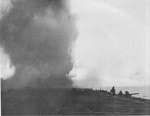
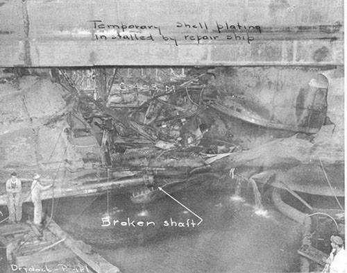
--25--
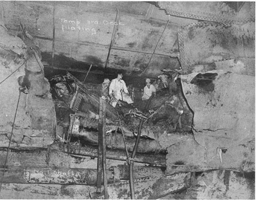
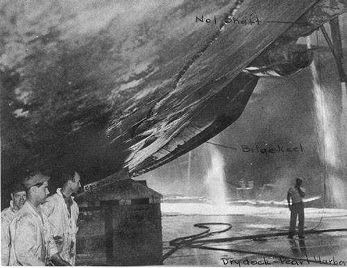
--26--
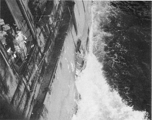
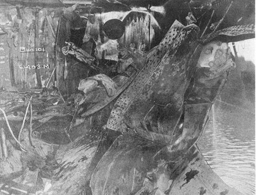
--27--
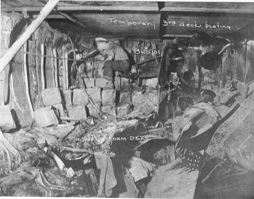
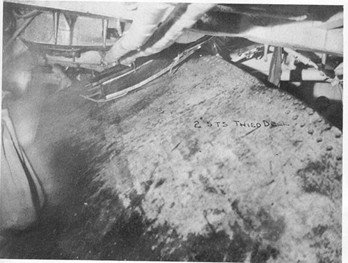
--28--
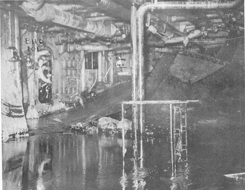
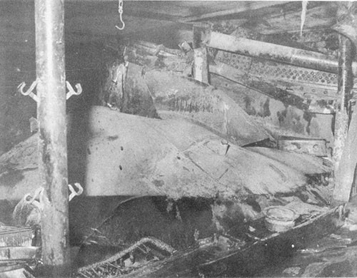
--29--
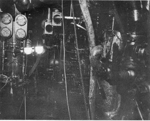
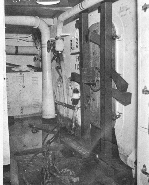
--30--
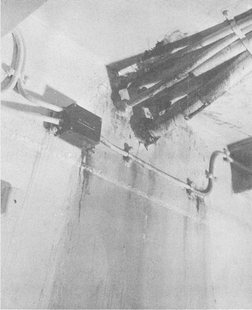
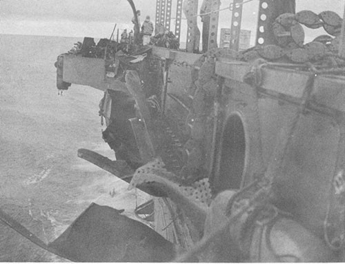
--31--
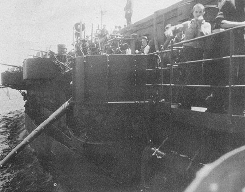
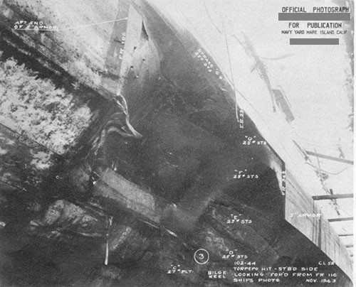
--32--
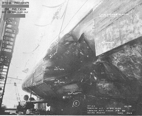
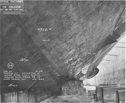
--33--
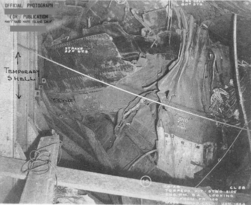
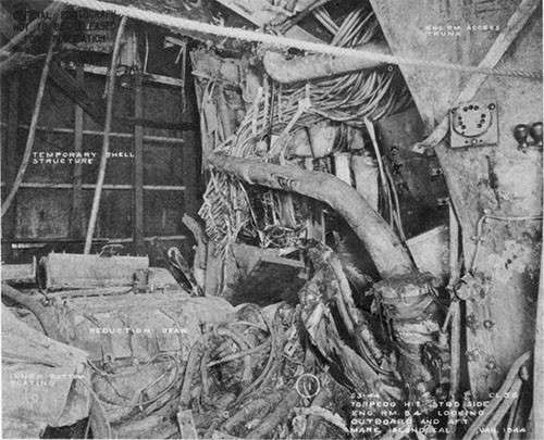
--34--
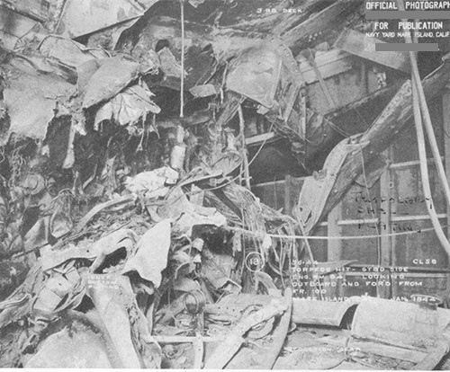
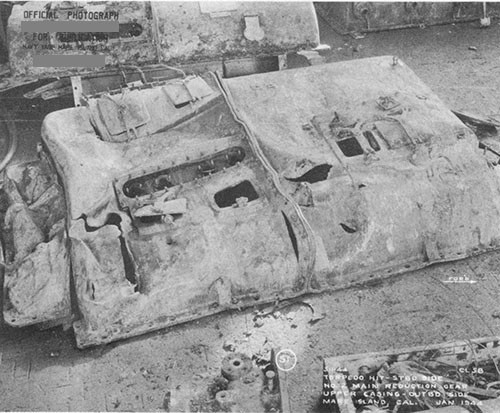
--35--
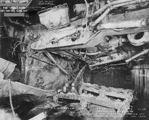
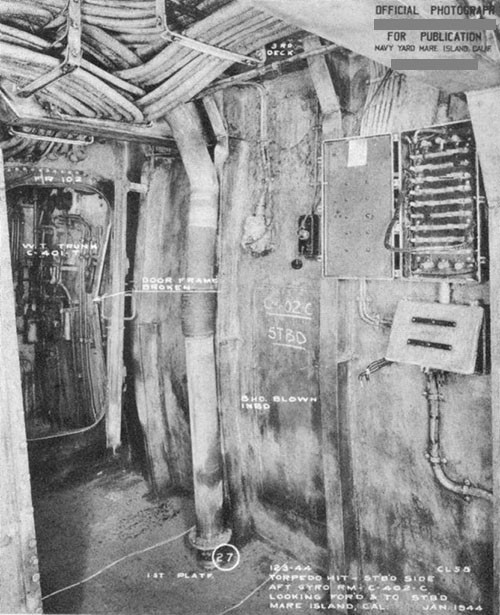
--36--
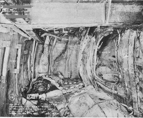
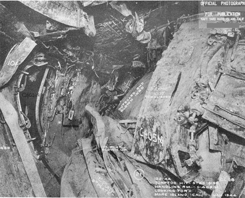
--37--
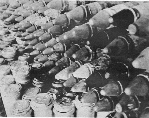
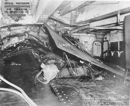
--38--
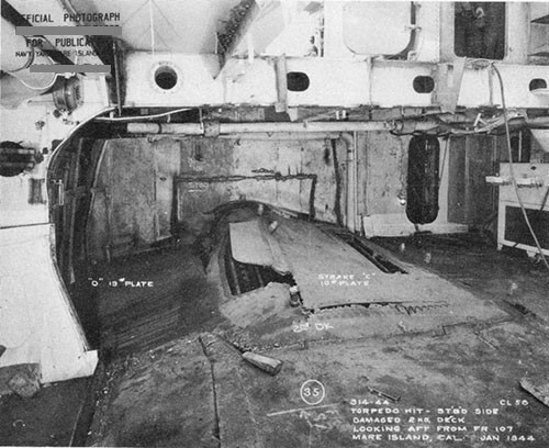
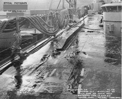
--39--
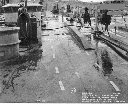
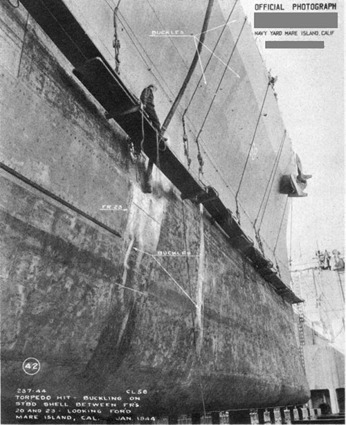
--40--
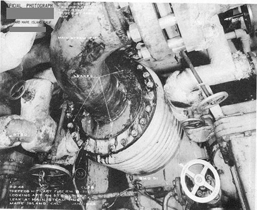
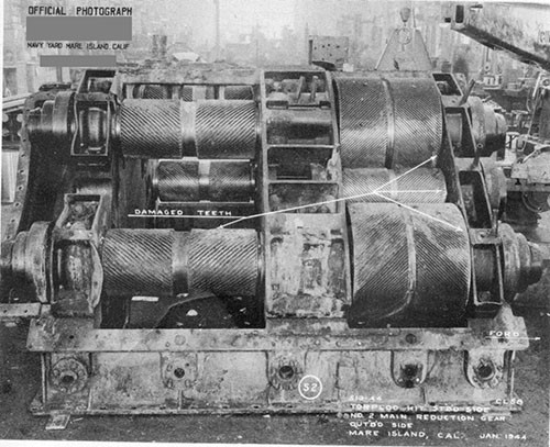
--41--
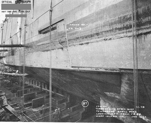
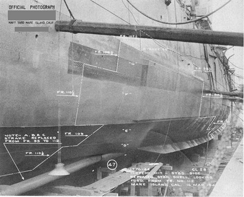
--42--
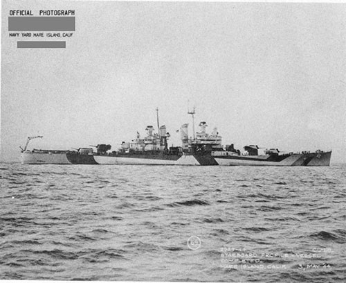
--43--
