The Navy Department Library
USS Canberra (CA70)
Torpedo Damage
Formosa
13 October 1944
CONFIDENTIAL
U.S.S. Canberra (CA70)
Torpedo Damage
Formosa
13 October, 1944
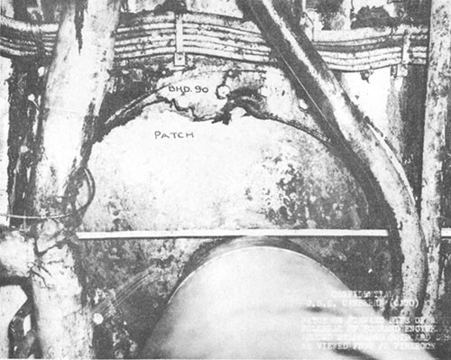
The Chief of Naval Operations directs that this report be shown only to those persons to whom the report would be of value in the performance of their duties.
Steps shall be taken accordingly to insure that the report will be seen by those persons responsible for design, construction and repair of naval vessels, as well as for their operation, but by no others.
Preliminary Design Section
Bureau of Ships
Navy Department
1 August 1946
WAR DAMAGE REPORT No. 54
U. S. S. CANBERRA (CA70)
TORPEDO DAMAGE
FORMOSA
13 OCTOBER 1944
| Class | (CA68-71) | Length (O.A.) | 673 Ft. 5 In. |
| Launched | 19 April 1943 | Beam (O.A.) | 70 Ft. 10 In. |
| Displacement (Standard) |
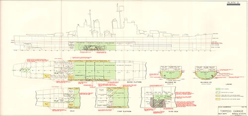
13,600 tons | Draft (Before Damage) | 24 Ft. 2 In. |
References:
(a) C.O. CANBERRA ltr. CA70/A16-3(60-ked), Serial 078 of 27 October 1944 (Action Report).
(b) C.O. CANBERRA ltr. CA70/A16-3(2), Serial 0032 of 24 November 1944 (Supplementary Action Report).
(c) C.O. CANBERRA ltr. CA70/A16-2(10-cdw), Serial 0036 of 30 November 1944 (Battle Damage in Forward Engineroom).
(d) C.O. CANBERRA ltr. CA70/A16-3(10-dts), Serial 0039 of 13 December 1944 (Battle Damage Report).
(e) C.O. ABSD-2 ltr., Serial 1015 of 20 January 1945, (Supplementary War Damage Report).
CONTENTS
| Section | Page | ||
| I | Foreword | 1 | |
| II | Summary | 1 | |
| III | Narrative | 2 | |
| IV | Discussion | 12 | |
| A. | Type of Torpedo | 12 | |
| B. | Structural Damage | 1 | |
| C. | Machinery Damage and Engineering Note | 14 | |
| D. | Flooding and Stability | 17 | |
| E | Damage Control | 18 | |
| F. | Miscellaneous | 18 | |
| G. | Conclusion | 19 | |
LIST OF PHOTOGRAPHS
| Photo | Title |
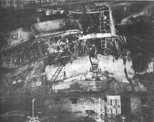
| 1. | Starboard side in way of hit looking into No. 4 fireroom. |
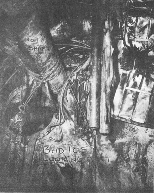
| 2. | Starboard side in way of hit with shell and double bottom removed. Note bend in No. 1 shaft. |
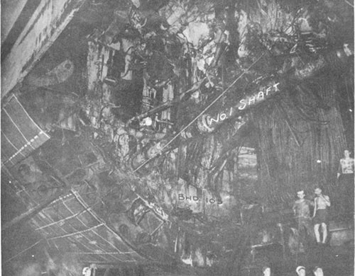
| 3. | Starboard side looking aft into No. 4 fireroom. Note tear in bulkhead 105 caused by displacement of No. 1 shaft. |
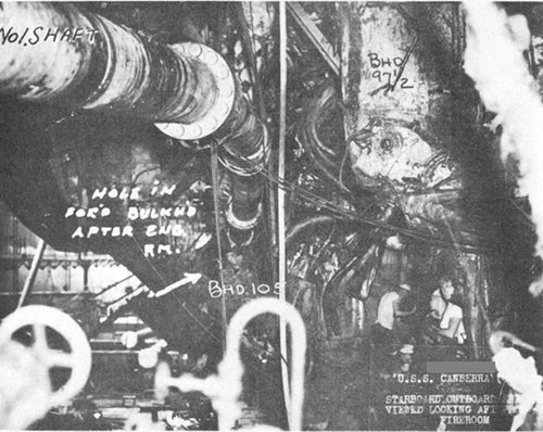
| 4. | Starboard side looking aft from No. 3 fireroom into No. 4 fireroom. Note distortion of No. 1 shaft, tear in bulkhead 105 and extent of damage to bulkhead 97-1/2. |
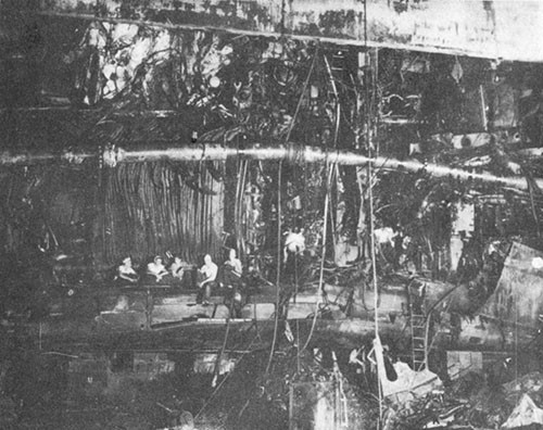
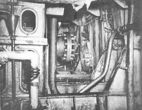
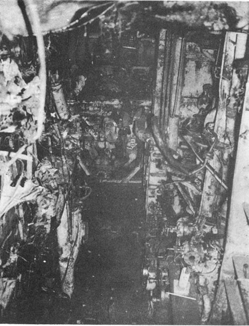
| 5. | No. 4 fireroom looking aft showing distortion of No. 1 shaft in way of bulkhead 105. |
| 6. | View taken from No. 3 fireroom showing patch on forward side of bulkhead 90 in way of No. 1 shaft installed by ship's force and salvage crew from CURRENT. |
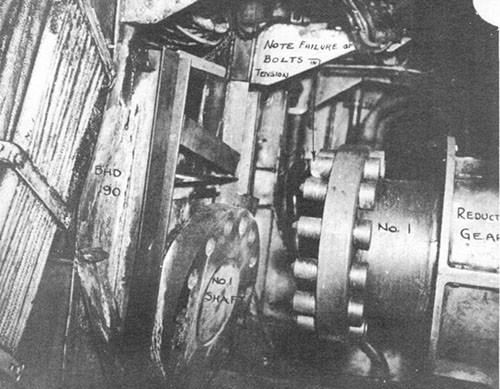
| 7. | No. 1 engineroom looking to port showing No. 1 shaft parted at flange coupling. Note failure in tension of flange bolts at termination of threaded portion of bolts. |
| 8. | Same as Photo 7 but looking to starboard. Note similarity in mode of fracture of all flange bolts. |
| 9. | Looking down into No. 4 fireroom. |
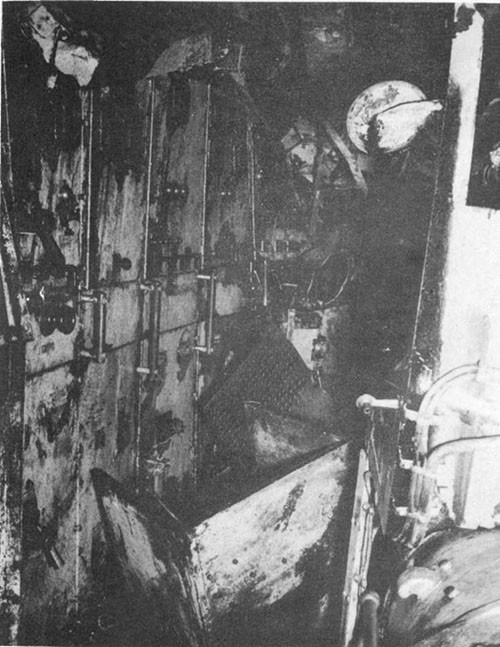
| 10. | No. 3 fireroom showing No. 3 main switchboard. |
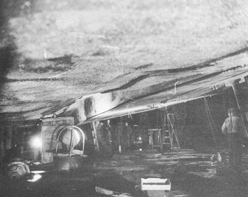
| 11. | Starboard side looking forward showing lower edge of patch at longitudinal No. 3 installed at Manus. |
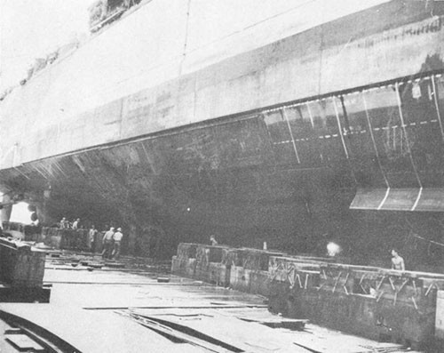
| 12. | Starboard side looking aft showing completed patch. |
| 13. | Starboard side forecastle, looking forward showing buckled deck. |
| 14. | Improvised casualty power terminals. |
| 15. | Improvised casualty power panel. |
| 16. | Improvised casualty power panel for evaporators. |
SECTION I - FOREWORD
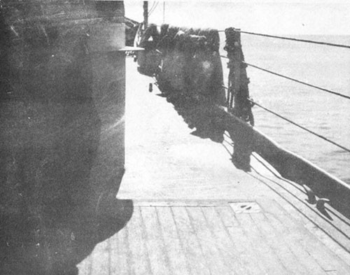
1. CANBERRA, was damaged by a single aircraft torpedo which struck in way of No. 4 fireroom at about frame 99, flooding Nos. 3 and 4 firerooms and Nos. 1 and 2 enginerooms. As a result of the flooding all propulsive power was lost and the ship lost way within a few minutes. The damage takes its place with that incurred by HOUSTON later in the same operation as one of the two instances in which U.S. cruisers have been immobilized as a result of a single torpedo hit.
2. The immobilization of CANBERRA led to considerable speculation as to the vulnerability of U.S. cruisers and the potency of Japanese torpedoes. A thorough analysis of the case, however, leads to the conclusion that the large extent of flooding was caused by the distortion of one propeller shaft which damaged two bulkheads otherwise untouched by blast or fragments from the detonation. The distortion was attributable to the location of the point of impact of the torpedo. This was almost directly beneath the shaft.
3. Damage control efforts were notable for the thoroughness of preparations made by the damage control organization of CANBERRA before damage was incurred and for the vigor and ingenuity with which machinery salvage operations were carried out while the ship was being towed from the combat area.
4. This report is based on the excellent and complete data contained in the references and reports of inspections of representatives of the Bureau both at advance bases and at Navy Yard, Boston. The photographs of damage to CANBERRA were furnished by the Commanding Officer and USS ABSD-2. The plate was prepared from plans submitted by ABSD-2.
SECTION II - SUMMARY
5. At 1835 on 13 October 1944 CANBERRA*, while participating in carrier strikes of Task Force 38 against targets on Formosa, was struck on the starboard side by an aircraft torpedo. The torpedo struck at frame 99 about 6 feet above the keel line, resulting in the flooding of all machinery spaces except Nos. 1 and 2 firerooms and the loss of all propulsive power.
6. Although extensive, the damage to the hull was of the same order of magnitude as that observed in other U.S. cruisers damaged by torpedoes. The side and bottom plating was ruptured from frame 95 to frame 104 starboard and from approximately 15 feet outboard of the keel upward to the armor belt. Nos. 3 and 4 firerooms flooded instantly. The starboard half of
____________
* It is interesting to note that although CANBERRA and HOUSTON (damage discussed in War Damage Report No. 53) were the only units in the Task Force to receive more than superficial damage, the Japanese propaganda machine at this time attempted to rekindle fading memories of Tsushima with a synthetically fabricated "victory" over the United States Pacific Fleet in the waters off Formosa. Newspapers carried banner headlines proclaiming the victory and commentators expanded an Imperial Headquarters communique claiming the sinking of 17 American ships and the destruction of 112 planes, inflating it to the sinking of more than 50 ships and the destruction of over 1,000 planes.
--1--
bulkhead 97-1/2 was blown forward and the lower portion jammed upward against the first platform in No. 3 fireroom. No. 1 shaft was deflected upward and inboard in a long sweep, tearing holes in bulkheads 90 and 105, which resulted in the rapid flooding of Nos. 1 and 2 enginerooms (Plate I and Photo 2).
7. Although all propulsive power was lost, Nos. 1 and 2 firerooms continued in operation and Nos. 1 and 2 turbo-generators and the forward and after emergency Diesel generators furnished power for general service and guns.
8. WICHITA (CA45) took CANBERRA in tow and started the retirement to Ulithi. Tow was later transferred to tugs. Damage control and salvage operations, commenced immediately following the hit, were continued en route. Upon arrival at Ulithi on 27 October, temporary repairs, including dewatering of the forward engineroom, were accomplished and the ship was then towed to Manus, arriving on 17 November.
9. At Manus, CANBERRA was docked in ABSD-2 simultaneously with CLAXTON (DD571) and KILLEN (DD593), both of which also required battle damage repairs. After completion of temporary repairs which included patching and strengthening the hull, dewatering all flooded spaces and reconditioning machinery in both enginerooms, she returned under her own power via the Canal Zone to Navy Yard, Boston, where permanent repairs were completed 10 October 1945.
10. The immobilization of CANBERRA was due to the location of the torpedo impact almost directly underneath No. 1 shaft and about 6 feet aft of the main transverse bulkhead separating Nos. 3 and 4 firerooms. The detonation violently displaced the shaft upward and inboard in the long arc shown in Photo 2. This movement broke the reduction gear coupling in the forward engineroom permitting lateral and upward movement of the shaft where it passed through bulkhead 90, tearing the hole shown in Photo 6. Likewise, bulkhead 105 was damaged by displacement of the shaft. Thus, both enginerooms were flooded although the two bulkheads in question were not damaged either by blast or by fragments. Measures to prevent such shaft damage to otherwise intact bulkheads were investigated thoroughly, but the cost in weight and space precluded the adoption of supporting devices sufficiently rigid to be of any value. Another factor was the small probability of the recurrence of a similar casualty. Of eleven U.S. cruisers torpedoed in way of machinery spaces, only CANBERRA suffered lateral derangement of a main propeller shaft.*
11. The successful retirement some 1400 miles to Ulithi through waters in which CANBERRA was still subject to attack from Japanese submarines and aircraft was the result of the skill and determination of her personnel and of the Task Group assigned to aid her. It is illustrative of the major advances in damage control and salvage technique made by the operating forces during the war.
SECTION III - NARRATIVE
12. On the evening of 13 October 1944, CANBERRA, a unit of a Task Group composed of two CV's, two CVL's, three CA's, and eight DD's, was operating off the Island of Formosa. Speed of ships in the group was reduced
___________
* It is to be noted that HOUSTON suffered longitudinal derangement of the broken shaft.
--2--
to 12 knots in order to recover planes. The sky was heavily overcast and visibility was on the dark side of twilight. A moderate sea with moderate swells was running. Sunset was at 1824.
13. The ship was in condition of readiness "One Easy" which provided for AA guns to be manned, and in material condition Modified "Zebra" which permitted certain doors on the starboard side of the second deck for access to galleys and utility spaces as well as two scuttles on the second deck leading to crew's heads on the third deck to be open. No third deck doors were open. Ventilation supply systems to below-deck stations were in operation. The main battery was not manned and access doors and hatches to all magazines and handling rooms were closed. Condition of the engineering plant was as follows:
(a) Main engines were operating to give a speed of 12 knots.
(b) The machinery plant was completely split at bulkhead 90 with No. 1 boiler furnishing main steam for No. 4 main engine and No. 1 turbogenerator, No. 2 boiler furnishing main steam for No. 1 main engine and No. 2 turbo-generator, No. 3 boiler furnishing main steam for No. 3 main engine and No. 3 turbo-generator, and No. 4 boiler furnishing main steam for No. 2 main engine and No. 4 turbo-generator.
(c) Nos. 1 and 2 evaporators and the emergency evaporator were distilling to potable water bottom tanks.
(d) Each turbo-generator was feeding its own distribution board and each board was supplying its normal load circuits. No boards were tied together. The forward and after emergency Diesel generators were set for automatic starting.
(e) The ship had been fueled on 11 October and had on board approximately 81 per cent of full capacity of fuel oil. Seven fuel oil ballast tanks had been ballasted and all other fuel oil tanks, except four overflow tanks which were empty or nearly so, were between 95 and 100 per cent full.
(f) The firemain was split into four sections with turbine-driven fire and flushing pumps in each of the four firerooms, and the motor-driven fire and flushing pump in the forward engineroom on the line with pressure being maintained at 115 pounds per square inch.
14. At 1833 low flying planes were picked up by radar and almost immediately screening ships commenced firing. On TBS signal from the Task Group commander, an emergency turn to the left was ordered and speed of 22 knots rung up. Simultaneously, enemy planes were observed breaking through the screen at a distance of about eight to ten thousand yards and firing became general. A group of 6 to 8 planes flying very close to the water closed the Task Group from the starboard quarter. Three of the planes were seen to crash under concentrated machine gunfire from two of the carriers. The remaining four planes turned sharply to the left and commenced a run on CANBERRA. Three were shot down by fire from CANBERRA; one crashed about 1000 yards off the starboard bow and the other two on the starboard beam at a distance of approximately 750 yards. The fourth plane, under continuous heavy machine gunfire, determinedly pressed home his attack and is believed to have launched a torpedo before crashing in flames about 1500 yards astern. No one reported having seen a torpedo dropped but almost simultaneously with the crash of the fourth plane, a torpedo wake was observed approaching the ship on the starboard side. Although increased speed had been rung up
--3--
and the rudder put left, the ship had not responded to the increased turns and had hardly swung off course when the torpedo struck on the starboard side at frame 99. This occurred at 1835.
15. Detonation of the torpedo was accompanied by a large ball of flame which shot up the side of the ship to about mast height followed by a geyser of water. The detonation and resultant shock were followed by flexural vibrations of the hull principally in a vertical plane.
16. Fuel oil, blown out of No. 4 fireroom air intake, covered the main deck in the vicinity but did not ignite. Damage to the main deck and topside structures was negligible.
17. Nos. 3 and 4 firerooms were opened to the sea and flooded immediately. There were no survivors from these spaces.
18. A flash was observed in the after starboard corner of the forward engineroom and the space filled with dense smoke. Water poured into the lower level through the after bulkhead in way of No. 1 shaft. An attempt to put main circulators on bilge suction was abandoned because of dense smoke and the rate at which the space was flooding. Within five minutes the water level reached the upper level and the engineroom was abandoned. Evacuation was via the access trunk to the third deck. Hatches were dogged down. The space flooded full in about ten minutes.
19. Circumstances in the after engineroom were similar to those in the forward engineroom, except that in addition to filling with smoke, the space also filled with steam. Flooding occurred through a hole in the forward bulkhead in way of No. 1 shaft at a faster rate than in the forward engineroom. All personnel evacuated via the access trunk. Personnel who escaped estimated that the space flooded full in about four minutes.
20. Steam was lost immediately in the after engineroom and Nos. 2 and 3 shafts stopped. No. 1 engine stopped immediately as a result of the damage to No. 1 shaft. No. 4 engine was secured two or three minutes after the hit occurred.
21. The rudder, which had been put over just prior to the hit, locked at 17 degrees left. Steering power was lost, and although the after emergency Diesel generator started as designed, emergency power was not available immediately because circuit breakers on the Diesel board kicked out and would not stay in. An unsuccessful attempt was made to position the rudder by use of chain falls. It was positioned finally by judicious use of the roll of the ship, permitting the rudder to swing toward amidships and preventing it from swinging back by manipulating hydraulic valves.
22. Nos. 1 and 2 firerooms continued in operation, furnishing auxiliary steam to Nos. 1 and 2 turbo-generators. The main feed pumps in No. 1 engineroom were secured, and the emergency feed pumps started immediately after the hit. The ship's practice of keeping casualty power cables strung along the third deck and connected at bulkhead terminals greatly facilitated the utilization of casualty power where needed in the after part of the ship.
23. As soon as it was evident that both enginerooms were flooding rapidly and that all propulsive power was lost, preparations were commenced for towing. WICHITA was designated to tow and passed over a 7-inch messenger which fouled and parted before her towing wire could
--4--
be brought aboard. CANBERRA then sent a 5-inch messenger to WICHITA. Since the ships were close together, this proved to be strong enough and WICHITA's towing wire was brought aboard. Considerable additional delay was caused by the fact that WICHITA did not send a shackle in the eye of the towing wire and CANBERRA's towing shackle was too large. The port chain was finally shackled to the wire with two spare shackles after about 2-1/2 hours. The chain was veered to 45 fathoms and towing commenced. Normal power from the forward main distribution board was available at all times to the anchor engine. CANBERRA's towing wire and all necessary gear were laid out on the forecastle to be used in case WICHITA's wire parted.
24. In addition to complete flooding of both enginerooms and the after firerooms, minor flooding occurred in the following spaces (Plate I):
(a) Compartment B-317-L, frames 97-1/2 - 105, starboard side, third deck flooded to a depth of about one foot through trunk (B-317-T) leading to No. 4 fireroom. The armored hatch in this trunk was blown up. The lower portion of the trunk and the watertight door above the third deck, which are armored, remained intact but the upper half of the trunk which is not armored was badly distorted. The frame around the periphery of the door was distorted, leaving a gap 3 to 4 inches wide which permitted water to overflow into the third deck space when the ship rolled. The door was shored and the gap plugged, allowing compartment B-317-L to be dewatered without difficulty.
(b) Port and starboard shaft alleys (C-602-E and C-603-E) flooded to depths of 2-1/2 and 3 feet, respectively, from the after engineroom through leakage around the shafts. This was reduced to negligible seepage by the use of marlin and wedges.
(c) The after Diesel generator room (C-402-E), on the first platform, flooded to a depth of 3 inches from the after engineroom through electric cable bulkhead stuffing tubes.
(d) The deck of the after gyro room (C-401-C), on the first platform, was covered with about an inch of water which seeped through electric cable bulkhead stuffing tubes from the after engineroom.
(e) 5-inch projectile magazine (C-501-M), on the second platform, flooded to a depth of 6 inches from the after engineroom through electric cable bulkhead stuffing tubes.
(f) Bomb magazine (C-513-M), on the second platform, flooded to a depth of 2-1/2 feet through a small crack in way of the forward strut for No. 2 shaft.
(g) 40mm magazine (C-601-M), in the hold, flooded to a depth of 8 inches from the after engineroom through electric cable bulkhead stuffing tubes.
(h) Leakage around the rudder stock and through a faulty check valve in the bilge eductor line was aggravated somewhat by the shock of the detonation. The loss of firemain pressure aft made the eductor inoperable and minor flooding occurred in the steering gear room before a portable electric submersible pump was placed in operation.
(i) Water seeped into magazines, C-403-M, C-405-M, C-503-M,
--5--
and C-606-M through electric cables and bulkhead stuffing tubes in minor amounts.
(j) Fuel tanks B-941-F, B-947-F, B-955-F, B-961-F, and B-965-F were ruptured and tanks C-523-F, C-903-F and C-905-F were flooded, probably through overflow lines from the ruptured tanks. Except for C-903-F tanks were 95-100 per cent full and the flooding had little effect.
(k) Potable and make-up feed water tanks under Nos. 3 and 4 firerooms were destroyed, but inasmuch as they were 95-100 per cent full, the flooding had little effect.
25. Draft increased from 22 feet 7 inches forward and 25 feet 10 inches aft to 25 feet 0 inches forward and 31 feet 0 inches aft. The ship assumed a starboard list of 1 to 2 degrees which gradually disappeared as oil was used from the starboard tanks.
26. Immediately after damage was incurred attention was turned to establishing flooding boundaries, stopping leakage and dewatering spaces which were not in communication with the sea. During the night most of the damage water was removed from compartments outside of machinery spaces. Submersible and handy billy pumps, bucket brigades and auxiliary drains were used. Considerable difficulty was caused by clogging of pump strainers and improvised box strainers were rigged. Difficulties were also experienced in pumping combinations of fuel oil and water with 2-1/2-inch submersible pumps. It was reported that the fuel oil clogged the pump and caused the motors to burn out. Leakage of water from flooded machinery spaces through electric cable stuffing tubes was reduced to a minimum by setting up and packing gland nuts.
27. The after bulkhead of No. 2 fireroom and the after bulkhead of the after engineroom were shored.
28. The after gyro and repeaters were put out of commission by grounds and short circuits on the after gyro panel caused by water seepage through and around electric cables from the flooded after engineroom. The forward gyro was not damaged, but the follow-up circuits were put out of commission by shock, causing repeaters to fail temporarily. Until the forward gyro and repeaters were put back in order, CIC and Air Defense were furnished true headings from the standard magnetic compass by setting them on the master repeater by hand and transmitting them over repeater circuits which could be energized.
29. All primary sound powered telephone circuits aft of amidships failed immediately after the hit. JV and JZ circuits were inoperative throughout the ship. Ultimately all sound powered circuits which ran through damaged and flooded machinery spaces shorted out. Shift was made to auxiliary circuits but some of these were also inoperative, and others experienced a general fading in volume. XJV circuits were not restored for some time, and, in order to reestablish communication between the bridge and steering aft, a long emergency lead was strung between these stations.
30. Ship service telephones in the after superstructure and aft of flooded areas were inoperative due to cutting or grounding of cables which ran through the firerooms. All ship service telephones forward of the flooded areas remained in good working order.
--6--
31. Nos. 1, 2 and 4 MC circuits operated satisfactorily and were invaluable in directing work below deck from central station and in directing rigging for the tow. No. 21 MC circuit lost power temporarily as the result of a short circuit in the outlet leading to the forward engineroom. Normal service was reestablished when this line was cut out and a jumper rigged to central station. No. 20 MC circuit, all stations of which are above the main deck, remained operable.
32. After the hit, firemain pressure failed aft of frame 90 and the emergency electric fire pump in the steering gear room was not available immediately because of loss of power aft. When casualty power was made available, this pump was put into operation. However, it overheated and therefore could only be used intermittently. This condition was later remedied by ship's personnel. Jumper hose lines were led aft from forward fire plugs and hooked up to fire plugs in the after part of the ship.
33. Engineering personnel turned attention toward restoring power for lighting, guns, communications and F.C. circuits. Since all evaporators were located in flooded spaces, all possible measures to conserve fresh water were taken immediately.
34. Nos. 1 and 2 firerooms were isolated from the remainder of the engineering plant as much as possible to minimize damage. To isolate the 600-pound auxiliary steam line, the two valves in the line leading to No. 1 engineroom open under split plant conditions were closed. The 150-pound auxiliary steam line was isolated aft of No. 2 fireroom by closing one valve in the forward engineroom with the hydraulic control from the third deck.
35. Auxiliary exhaust was isolated by closing two valves in No. 2 fireroom and opening one valve in the cross connection between Nos. 1 and 2 firerooms.
36. The condensate line from Nos. 1 and 2 auxiliary condensers was broken at frame 79 in No. 2 fireroom and a blank metal gasket inserted allowing either auxiliary condensate pump to discharge to reserve feed bottoms in the adjacent firerooms.
37. The main cutout valve of the high pressure drain at frame 73 in No. 2 fireroom was closed. The main cutout valve of the low pressure drain at frame 80 in the forward engineroom was also closed. A reach rod extending through the bulkhead was used. The fuel oil heating system and fuel oil heater drain system cutout valves, the main cutout valve of the steam heat system drain and the fuel oil tank stripping line cutout valve, all in No. 2 fireroom, were closed. When it was discovered that salt water from flooded spaces was contaminating fresh water in reserve feed bottoms, the fresh water distribution line on the starboard side of No. 2 fireroom and the reserve feed distribution line on the port side were broken at flanges and blank metal gaskets inserted.
38. The constant steam supply line from the after engineroom was clamped off by using C-clamps and blocks permitting steam to be cut into the galley for cooking. About an hour after the hit No. 2 turbo-generator was secured, but steam was kept boosted on No. 2 boiler to supply No. 2 fire and flushing pump.
39. Leakage of water from flooded spaces through electric cables and bulkhead stuffing tubes caused considerable progressive shorting out of vital electrical circuits and a small amount of flooding in intact spaces, which damage control facilities controlled adequately.
--7--
40. The after gyro panel and the after emergency Diesel generator board, both located in spaces abaft the flooded after engineroom, were among the first vital units to short out. The after gyro became inoperable initially as a result of loss of power, and emergency power was not available immediately because of difficulty with circuit breakers on the after Diesel generator board. Within a short time after the hit, the after gyro power panel shorted out as a result of water seepage through cables from the after engineroom. Within about two hours water seepage through cables from the after engineroom also shorted out the after Diesel generator board. All cables which passed through flooded spaces were disconnected and pulled clear of the emergency Diesel generator board and after about six hours the generator was cut in again.
41. All cables to power panels and switchboards that were tied to Nos. 3 and 4 distribution boards were disconnected or cut and cleared where practicable.
42. During the following day water seeped through cables connected to the distribution panel in the ice machine room shorting it out and causing a fire. The fire was extinguished by CO2 but not in time to prevent irreparable damage to the panel and most fixtures. Power was restored to the compressor motor by connecting leads direct to the starting panel from the after Diesel generator using the casualty power system.
43. As time permitted, all casualty power terminals were checked and tightened and leads were secured out of the way in the overhead. Casualty power leads were run to the galley, after ventilation blowers, Nos. 7, 8 and 9 40mm quadruple mounts, and Nos. 5 and 6 5-inch mounts.
44. The final setup of electrical power was as follows:
(a) No. 1 turbo-generator supplied No. 1 board direct and No. 2 board through bus tie feeders.
(b) Nos. 1 and 2 boards supplied their normal loads which consisted of lighting and power circuits forward of frame 80.
(c) No. 1 board, in addition, supplied lighting and power circuits frames 80 to 120 through a casualty power lead on the starboard side.
(d) No. 2 board, in addition, supplied power to steering aft through a casualty power lead on the port side which was also available to furnish power to airplane handling machinery.
(e) Lighting and power circuits aft of frame 120 were supplied through a casualty power cable from the after Diesel generator board.
(f) The forward emergency Diesel generator was set to start automatically and No. 2 turbo-generator was used as a standby.
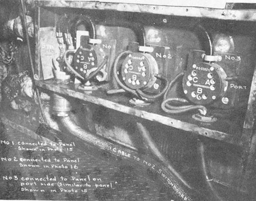
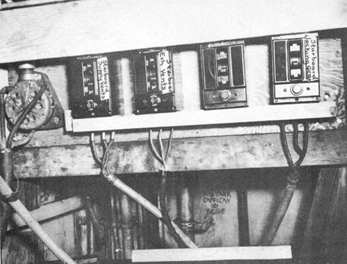
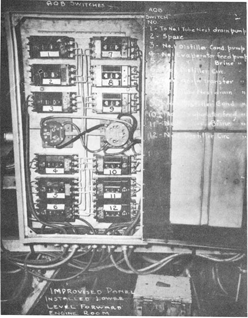
(g) Photographs Nos. 14, 15 and 16 show casualty power panels rigged in No. 1 engineroom to distribute casualty power from No. 2 board to auxiliaries in the engineroom after it was dewatered at Ulithi.
45. On 15 October tow was transferred from WICHITA to MUNSEE (ATF107) and at 1212 the group joined the damaged HOUSTON (CL81) being towed by BOSTON. Towing speed was about 4-1/2 knots.
--8--
46. At 2200 on 15 October No. 1 emergency feed pump broke down. It was reported that the piston shattered, possibly due to misalignment from shock. No. 2 boiler was put on the line and No. 1 boiler secured. Continuous salinity tests on No. 2 boiler feed water showed that salinity was increasing rapidly. It finally reached about 1800 grains per gallon despite continuous dosage with Navy boiler compound carried out in accordance with instructions published in BuShips Bulletin of Information No. 13 of 1 January 1944. A diver was sent down into the forward engineroom to close an additional valve in the auxiliary steam line so that No. 1 boiler could supply steam to No. 2 emergency feed pump without losing steam to the engineroom. No. 1 boiler was lighted off with No. 2 emergency feed pump supplying feed water through the auxiliary feed cross connection. No. 2 boiler was dumped and the firesides inspected. The boiler was then refilled and kept in a standby condition. Steam pressure was boosted at regular intervals. Each day while en route under tow additional fresh water was taken on from ships in the group.
47. On 20 October a salvage officer and divers from CURRENT (ARS-22) came on board to assist in diving and salvage operations which had been started by CANBERRA's personnel. Divers reported that there was a hole approximately 34 inches in diameter in way of No. 1 shaft in bulkhead 90, the after bulkhead of No. 1 engineroom. The damaged bulkhead shaft gland, the shaft revolution counter gear box and foundation for same, the sheet metal guard over the shaft coupling, and electric cables in the vicinity of the hole in the bulkhead were removed. The jagged edges of the hole in the bulkhead were trimmed with an electric underwater cutting torch and a patch was shored in place. The patch proved to be non-tight, however, and the water level in No. 1 engineroom could be lowered only about two feet despite the help of additional pumps supplied by CURRENT.
48. Fitting of a second patch made up of 15 pound plate with sufficient overlap to provide seating surface for a 1/4-inch rubber gasket was started immediately after failure of the first patch (Photo 6).
49. WATCH HILL (W.S.A. Tug) joined MUNSEE on 20 October 1944 and the two tugs towed CANBERRA in tandem. The tow arrived off Mugai Channel, Ulithi at 0530 on 27 October 1944 and prepared to enter the atoll. At 1318 CANBERRA anchored in her assigned berth and AJAX (AR6) came alongside to port to assist in salvage operations and temporary repairs.
50. While the towing operation was underway and while work proceeded on the installation of the patches, the following machinery was salvaged from the forward engineroom in order that No. 2 evaporator might be placed in operation as soon as the engineroom was dewatered:
No. 2 Evaporator Condensate pump and motor
No. 2 Evaporator Brine overboard pump and motor
No. 2 Evaporator Distiller circulator pump and motor
No. 2 Evaporator Feed pump and motor
No. 2 Evaporator First effect coil drain pump and motor
Motor for No. 2 fresh water drain transfer pump
The pumps were reconditioned and the electric motors washed in improvised tanks on the main deck with hot water heated by live steam. The motors were treated with tectyl after washing and baked out under improvised ovens heated by electric light bulbs. The components of No. 1 main evaporator were treated similarly at Ulithi.
--9--
51. Installation of the second patch was completed 28 October 1944 and pumping operations were resumed. The water level was lowered 11 feet 2 inches below the third deck within three hours and then held at that height pending a decision to shore bulkhead 90.
52. After a decision was made to shore the bulkhead, pumping was resumed and shoring installed as the water level was lowered. Considerable difficulty was experienced with clogging of pump strainers by debris from asbestos lagging and insulation material. 6-inch portable electric pumps obtained from CURRENT proved to be the most satisfactory equipment for this duty. Additional minor leaks were stopped and eventually leakage was controlled by operating small portable electric submersible pumps intermittently.
53. Work of salvaging and reconditioning machinery in the forward engineroom continued and after all damage water was removed it was possible to assess damage sustained in this space.
54. There was no structural damage to bulkhead 90 other than the hole in way of No. 1 shaft. Minor leaks noted above were in way of electric cable bulkhead stuffing tubes.
55. No. 1 main propulsion unit was the only machinery in the forward engineroom which sustained damage other than by immersion. All bolts in the coupling abaft the reduction gear failed in tension and the shaft pulled aft, finally coming to rest with a space of 12 inches between the flanges (Photos 7 and 8). The shaft apparently rotated slightly after parting at the coupling which may account for the oval shaped hole in the bulkhead. The bulkhead gland was pulled aft through the bulkhead. The casing of No. 1 main reduction gear did not show any apparent damage. When the top was lifted it was found that the unit had not filled completely when submerged and as a result corrosion had started on the exposed teeth. All gears, pinions and journals were cleaned and treated with tectyl and consol. The flange of the bull gear shaft was checked for misalignment using two dial indicators, one on the face and one on the periphery, and the shaft was found to be slightly out of alignment.
56. Electric motors and pumps which were reconditioned as described in paragraph 50 were reinstalled and the main evaporators put back in operation. Photo 16 shows the improvised distribution panel installed in No. 1 engineroom to distribute casualty power to the evaporators. Since the exhaust line from No. 3 fireroom was ruptured in that space, it was necessary to crimp the line just aft of No. 1 evaporator in the forward engineroom in order to prevent salt water from entering the evaporators from aft.
57. On 10 November, CANBERRA departed Ulithi under tow and proceeded to Seeadler Harbor, Manus. No. 4 main propulsion unit had been put in a ready condition, but because of the submergence of No. 4 shaft and its spring bearings in way of the flooded spaces, it was decided to tow the ship to Manus rather than risk damage to bearings from lubrication failure. The tow arrived at Seeadler Harbor on 17 November and on 1 December CANBERRA was docked in ABSD-2 simultaneously with CLAXTON (DD571) and KILLEN (DD593), both of which also required battle damage repairs.
58. It was planned to accomplish temporary repairs to the hull, dewater remaining flooded spaces, salvage and treat for preservation
--10--
machinery and equipment worth salvaging in Nos. 3 and 4 firerooms and recondition machinery in the after engineroom for temporary operation, pending permanent reconditioning and repairs in the United States.
59. It was now possible to assess damage to the ship's structure and machinery in way of the hit. The opening in the shell plating and inner bottom was irregular in shape and extended between frames 95 and 104 and from about 15 feet to starboard of the keel to the lower edge of the armor belt. Plating at the periphery of the opening was deflected inboard and somewhat upward; deformation extended from frame 90 to 109 and from about 15 feet from the keel on the port side to about 3 feet above the lower edge of the armor belt on the starboard side (Photo 1).
60. The flat keel was buckled and raised between frames 95 and 109 with a maximum deflection of 2-3/4 inches at frame 99. There was no apparent distortion of the armor belt (6-inch tapered to 4-inch Class A armor). Bulkhead 97-1/2 between Nos. 3 and 4 firerooms was demolished from the starboard shell to the centerline (Photo 4).
61. The third deck (2-1/2-inch STS) was deflected upward a maximum of 3 inches on the starboard side, frames 95-107, but was not ruptured. Armored hatch 3-97-1 leading to trunk B-319-T was blown upward and torn from its hinges, finally coming to rest upside down. The upper half of trunk B-319-T, which was not armored, was distorted. Door 3-99 in the trunk was not distorted but the frame around the upper periphery of the door pulled away, leaving an opening of about 3 inches. The lower half of the trunk and watertight door, both of which are armored (1-inch STS), remained intact with no apparent damage. The access trunk to No. 3 fireroom below armored hatch 3-96 was demolished to within a few feet of the third deck but the armored hatch remained intact. Bulkhead 97-1/2, on the third deck, was distorted on the starboard side and watertight door 3-97-1 was sprung, leaving a gap of about 3 inches at the top. Several stanchions in B-317-L over the center of the detonation were bent when the deck was raised.
62. The only appreciable damage to bulkhead 105 (after bulkhead of No. 4 fireroom) and bulkhead 90 (forward bulkhead of No. 3 fireroom) was that in way of No. 1 shaft caused by displacement of the shaft which assumed a long bend between bulkhead 90 and frame 106 with a maximum deflection at frame 99 of 4 feet 5 inches upward and 3 feet 3 inches inboard. Bulkhead glands at bulkheads 90 and 105 were torn away. The hole in bulkhead 90 was oval shaped, measuring approximately 34 inches on its longer axis. The final position of the shaft was approximately 8 inches below the intact position. The hole in bulkhead 105 was also oval, but measured approximately 60 inches on its longer axis. The final position of the shaft was approximately 27 inches upward and inboard, at an angle of 35 degrees with the vertical from its original position. (Photos 2, 3, 4 and 5, and Plate I).
63. There was minor structural damage caused by flexural vibration of the hull beyond the vicinity of the hit. The main deck was buckled slightly in the vicinity of frames 20 and 21, starboard side, (Photo 13); the second deck was buckled slightly between frames 24 and 25, starboard side; and secondary wrinkles developed in the bottom plating on the starboard side near frames 145 and 146.
64. Machinery, piping, fittings and electric cables on the starboard
--11--
side of Nos. 3 and 4 firerooms were demolished, (Photos 2, 3 and 4). In No. 4 fireroom the boiler on the starboard side was demolished and most of it was lost through the hole in the shell. Machinery and equipment on the port side, including No. 4 turbo-generator, were badly damaged by blast and immersion, but much was salvageable, (Photo 9).
65. Practically all machinery and equipment on the starboard side of No. 3 fireroom, including No. 3 turbo-generator, was damaged beyond repair, (Photo 10). No. 3 boiler, on the port side, was damaged but not beyond salvage.
66. In the after engineroom, the principal damage resulted from immersion.
67. Immediately after the water was removed from Nos. 3 and 4 firerooms and the after engineroom, attention was turned to salvaging and reconditioning machinery. All salvageable machinery in the after firerooms was cleaned, treated with tectyl and placed in a state of preservation. Machinery in the after engineroom was reconditioned for operation on the voyage back to the United States.
68. Hull repairs accomplished at Manus were intended to replace the original strength by the simplest means practicable and were to be of a temporary nature. Longitudinals, frames and shell plating were installed where necessary. New plates were installed flat, knuckled along longitudinal No. 6 and shaped at the forward and after ends of the patch to make proper transition into the original hull form, (Photos 11 and 12). Stanchions and transverse beams were installed on the starboard side in way of the missing section of bulkhead 97-1/2. The hole in bulkhead 105 was patched to restore the watertight integrity of the after engineroom.
69. Upon completion of temporary repairs and reconditioning of machinery, CANBERRA departed Seeadler Harbor on 13 January 1945 and proceeded to Navy Yard, Boston, operating on shafts Nos. 2, 3 and 4. She arrived at Boston 17 February 1945 and repairs were completed 15 October 1945. CANBERRA is now assigned to the Seattle Group of the Inactive Nineteenth Fleet.
SECTION IV - DISCUSSION
A. Type of Torpedo
70. The estimated point of impact of the torpedo which struck CANBERRA, approximately 18 feet below the waterline, is somewhat deeper than the average experienced in the past. The plane which launched the torpedo was identified either as a Betty or a Frances, either of which had a maximum bomb or torpedo load capacity of 2000 pounds, according to intelligence information. Some estimates have placed the warhead charge weight as high as 800 or 900 pounds. Although the Japanese developed an aircraft torpedo with an 812-pound warhead, intelligence information indicates that few if any were in service at the time CANBERRA was torpedoed. The extent of structural damage is consistent with that to be expected from the Type 91, Mod. 3 torpedo which was the type used most frequently by the Japanese. The warhead of this
--12--
torpedo contains 522 pounds of Type 97 explosive which consists of 40 per cent HND and 60 per cent TNT and is approximately as powerful as an equal weight of TNT. The U.S. aircraft torpedo in use during the last years of the war contained a warhead charge of 606 pounds of torpex which has an explosive force approximately equivalent to 900-1100 pounds of TNT.
B. Structural Damage
71. Structural damage sustained by CANBERRA was consistent with that of other cases of torpedo damage to vessels of comparable size. The location of the point of impact at frame 99 was such that only transverse bulkhead 97-1/2 sustained blast and fragment damage. There was no blast or fragment damage to either bulkhead 90 or bulkhead 105, and, except for the holes torn in the bulkheads as a consequence of the casualty to No. 1 shaft, large-scale flooding would have been confined to Nos. 3 and 4 firerooms. HOUSTON* also experienced a casualty to No. 1 shaft which permitted flooding of four machinery spaces.
72. It is significant that although the armored (2-1/2-inch STS) third deck was raised a maximum of 3 inches directly over the center of the detonation, it was not ruptured and effectively restricted damage and serious flooding to areas below the third deck level. On CHESTER (CA27) and MINNEAPOLIS (CA36)** the armored second decks (1-inch and 2-1/4-inch STS, respectively) restricted blast damage from torpedo hits in way of machinery spaces and prevented extensive damage to structure above that level. In the case of HOUSTON, the armored (2-inch STS) third deck was raised and torn open at a seam above a torpedo hit in a machinery space; the impact, however, was in way of the No. 1 reduction gear which was blown up against the overhead, thereby contributing considerably to the damage of the deck. FRANKLIN (CV13)*** is the most notable of another group of war damage cases in which the armored deck effectively protected spaces below against bomb damage. Thus, it has been demonstrated that armored decks not only provide effective protection against bombs, but restrict damage from underwater explosions.
73. Although the armored hatch in access trunk B-319-T was blown off its hinges, the armored (1-inch STS) lower half of the trunk on the third deck remained intact, preventing extensive flooding of third deck space B-317-L. Doctrine aboard CANBERRA was to leave the armored access hatches to the engineering spaces undogged. This was considered sound in view of the fact that watertight, partially armored trunks, fitted with quick-acting watertight doors to the third deck and with watertight hatches to the second deck, extended from the third to second decks, augmenting the watertightness of the armored hatch; and protection against missiles from above was given by the wide seating scarf in the armored hatch. The doctrine is justified when it is considered that all personnel escaped from both enginerooms even though the after space flooded to the third deck in approximately four minutes; whereas, only 17 of the 25 men in the after fireroom of HOUSTON escaped. The majority of those lost on HOUSTON appear to have been on the starboard side of the fireroom and were trapped as they attempted to open the armored hatch. The Bureau of Ships is presently conducting research leading to an improved design of an armored, watertight, quick-acting hatch.
____________
** War Damage Report No. 36.
--13--
74. A careful inspection of fragment damage to structure and equipment in Nos. 3 and 4 firerooms indicated that the fragments were from the ship's structure rather than from the warhead.
C. Machinery Damage and Engineering Notes
75. In general the performance of the machinery was satisfactory. It is almost inevitable that a torpedo hit in the middle one-half length will result in the flooding of at least two major spaces. The unusual displacement of No. 1 shaft which caused damage to bulkheads 90 and 105, resulting in the flooding of four major spaces, can be attributed to the location of the point of impact, which was almost directly beneath the shaft and adjacent to a steady bearing at frame 100 so that the force of the detonation was transmitted directly through rigid structure to the shaft.
76. In view of this casualty and the casualty to HOUSTON shafting, the design of improved spring bearings, thrust bearings and bulkhead shaft glands was investigated. The investigation indicated that spring bearings designed to successfully restrain lateral displacement of main shafting would be too costly in weight but that an auxiliary thrust bearing installed just forward of the stern tube stuffing box would not present the same objection and would prevent longitudinal displacement of the shaft and consequent damage to shaft glands. Therefore, auxiliary thrust bearings, but no additional restraints against lateral displacement, have been incorporated in the design of the CA139 class heavy cruisers. In order to protect against flooding of four main machinery spaces such as occurred in CANBERRA, an auxiliary machinery space 5 frame spaces or 20 feet in length has been placed between Nos. 2 and 4 machinery spaces in the CA139 class.
77. At the time of the hit, the engineering plant was in the most favorable condition of segregation to resist interruption of power as a result of damage. As far as practicable the plant was split into four units, each boiler furnishing steam to one main engine and its auxiliaries and each turbo-generator supplying its designated normal load. The fact that the ship made a practice of keeping casualty power cables connected to bulkhead terminals on the third deck made it possible to furnish casualty power to interrupted circuits more quickly than if it had been necessary to lead out cables after damage. As an additional facility for rapid utilization of casualty power, the ship had installed connections from the lower terminals of risers to distribution boards with suitable switches and circuit breakers so that risers could be energized quickly. Outstanding shipalts now provide that such installations will be permanent.
78. Feeder cables leading aft from Nos. 1 and 2 main switchboards in Nos. 1 and 2 firerooms were either cut in way of the hit or shorted out due to water entering the cables in way of the flooded machinery spaces. It was necessary to disconnect all cables at No. 2 switchboard which showed signs of seepage of water from aft. Normal feeders were used to supply power to the forward part of the ship and the casualty power system was used to furnish power aft. The after emergency Diesel generator started as designed and furnished power to a portion of its emergency leads until the switchboard shorted out due to seepage of water through cables from the flooded machinery spaces. When this occurred it was necessary to furnish all power aft via casualty
--14--
power leads from the forward firerooms. The load placed on casualty power leads was greater than that provided for in the initial design and consequently caused excessive heating of the risers. Other ships, including RENO and HOUSTON, reported similar difficulties. As a result, the General Specifications for Machinery have been amended to require the installation of additional risers to augment casualty power capacity from each main switchboard when the power load distributed by the switchboard exceeds 400 KW at service voltage.
79. There was some delay in utilizing casualty power in several instances because of difficulty in making connections to certain power panels. To alleviate this trouble in the future, the General Specifications for Machinery have been amended to require the installation of casualty power terminals on selected power panels and controllers.
80. Considerable ingenuity on the part of the ship's force was displayed in returning the evaporators in the forward engineroom to service, particularly auxiliary motors for pumps in the evaporator system. The motors were removed for reconditioning even before dewatering of the space had been completed. A fresh water tank supplied with live steam was erected on the main deck. Motors were washed with the hot fresh water, treated with tectyl and baked in an oven improvised from a canvas tent and heated by a number of electric light bulbs. When the forward engineroom was dewatered, the pumps and motors were reinstalled and Nos. 1 and 2 evaporators placed in operation. To facilitate operation of the motors by casualty power, an I.C. panel was converted into an improvised distribution board (Photo 16) using A.Q.B. switches. Power was at first supplied from the casualty power system on the third deck and later direct from No. 2 main switchboard through bulkhead 80. Other similar improvised panels were installed where needed to facilitate operation of electrical auxiliaries (Photos 14 and 15).
81. CANBERRA, as well as other ships including HOUSTON, RENO, DENVER and INDEPENDENCE, have had considerable difficulty with leakage of water through electric cable bulkhead stuffing tubes and seepage of water through cables from flooded compartments. Improved packing tubes, materials and methods together with modified specifications calling for additional slackness in cable runs between bulkheads should alleviate the difficulty with stuffing tubes to a considerable extent. Shipalts calling for cable end sealing for ships in service have been outstanding for some time and are being accomplished on a piecemeal basis. All cable produced for the Navy since 1 January 1945 has been of watertight construction.
82. Although CANBERRA experienced no difficulty with flooding out of casualty power bulkhead terminals on the third deck, the Commanding Officer recommended that terminals be relocated to the second deck. This is in line with the general policy of the Bureau to raise the location of all damage control equipment from the third to the second deck on three-deck vessels and from the fourth to the third deck on four-deck vessels, which policy was promulgated in the light of a large volume of war experience.
83. On the basis of war experience with the severance or flooding out of horizontal runs of power feeders, I.C. and F.C. cables, and to provide a system of electric cable routing which will be less vulnerable to total immobilization as a result of underwater attack, the General Specifications have been modified to provide for more effective separation of horizontal runs of duplicate cables. In general, port and starboard runs of cables will be on
--15--
different deck levels, one run being located above and one below the armored deck.
84. Failure of the chain falls provided to assist in positioning the rudder was probably due to faulty manipulation of hydraulic valves, thereby giving inadequate braking to the rudder motion (see paragraph 21). However, later attempts to position the rudder utilizing the swing of the rudder inboard caused by the roll of the ship and braking the outboard swing by manipulating hydraulic valves proved successful. Outstanding shipalts authorize the installation of a remote-controlled emergency electro-hydraulic submersible pump unit on all CV's, CVL's, CA's and CL's which may be used to control the rudder in the event of flooding of the steering gear room or casualty to the main source of steering power. This unit may be operated electrically by push button in the steering gear room or, in the event of flooding of that space, from the after gyro room on cruisers or from the Repair III station on carriers. If, in addition to flooding, power to the unit is lost, it may be operated remotely by mechanical hand-operated cranks from a deck above. This unit is in addition to the independent hand-operated pump previously provided in the steering gear room and to the chain hoists equipped with positioning blocks for positioning the rudder.
85. Leaks around the rudder stock and through a faulty check valve in the bilge eductor discharge, which had given trouble prior to the damage, were slightly aggravated as a result of the damage. Flooding of the steering gear room was a direct result of the failure of firemain pressure aft and the inability of the ship's personnel to get the after emergency fire pump on the line immediately, thereby leaving the bilge eductor inoperable. After a portable submersible electric pump was placed in operation, leakage was easily controlled by intermittent operation of the pump. Shipalts have been issued which provide for relocation of the emergency fire pump to a more accessible place in the engineer's storeroom C-529-A, installation on the second deck of remote controls for the motor and suction valve, removal of the eductor and all associated firemains and drains and installation of an 85 gallon per minute drainage pump in the steering gear room.
86. As a result of having to blank off certain auxiliary steam supply and exhaust lines and feed filling lines and having to close certain inaccessible or flooded auxiliary steam valves, the ship recommended that additional valves and remote controls be installed. After further study and consultation with ship's personnel, the existing arrangement of valves was found consistent with the size and general arrangement of the machinery plant and it was decided that additional valves would unnecessarily complicate the plant. It is believed not unreasonable to expect the ship's force to accomplish emergency measures such as blanking lines after cases of unusually extensive damage.
87. In order to provide additional emergency lines of communication for ship handling, the Master Allowance List was modified to provide three sound power telephone headsets together with 1000 feet of DHFW-1 cable for each CA. Provision is also being made for the installation of two sound power telephone risers from the steering engineroom and from each main engineroom to the main deck with jack boxes at the terminations plus a jack box on the bridge, two 150-foot lengths of DCOP-1/2 cable with single jack boxes on one end and type T telephone plugs on the other end and two 320-foot lengths of DCOP-1/2 cable with
--16--
type T plugs on each end. The cables will be used to link the bridge jack box with the main deck terminals of main or steering engineroom risers in the event of damage to primary ship handling circuits.
88. Although the propeller shaft coupling bolts are not deliberately designed as the weak point of the shafting system, numerous cases of damage to shafting have indicated that the bolts do almost inevitably fail first. The bolts on CANBERRA appear to have failed in tension at the termination of the threaded portion (Photos 7 and 8). The predisposition for failure of shaft bolts in tension rather than for fracture of the shafting is a most fortuitous circumstance inasmuch as a broken shaft requires replacement, but many shafts even though severely bent have been straightened and returned to service.
89. The Commanding Officer of CANBERRA noted that considerable difficulty was experienced with clogging of strainers over bilge wells when No. 1 engineroom was being dewatered. On the basis of CANBERRA's experience and that of numerous other vessels, a directive was issued in April 1945 to install box strainers with the total area of holes equal to four times the area of the suction line over machinery space bilge wells. Further consideration has indicated the desirability of even larger strainers and the General Specifications for Machinery are being amended to require box strainers approximately 3 feet high or at least extending from the tank top to the underside of the lower gratings.
90. Despite difficulties experienced by CANBERRA in pumping combinations of oil and water with 2-1/2-inch submersible pumps, (see paragraph 26), tests performed by the Engineering Experiment Station, Annapolis, Maryland, reported in BuShips Bulletin of Information No. 19, dated 1 July 1945, and the experiences of other vessels, notably HONOLULU, indicate satisfactory operation under similar circumstances on the part of pumps of the same make as those used by CANBERRA. A thorough study of portable pump allowances on combatant vessels has been completed recently in conjunction with Forces Afloat and it is not contemplated to increase the allowance for CA's above the twelve portable pumps and two complete sets of spare parts now authorized. Six-inch portable submersible electric pumps such as those obtained by CANBERRA from CURRENT are considered to be too unwieldy to be placed on board combatant ships as a regular unit of the damage control allowance. Two such pumps have been furnished each salvage ship.
D. Flooding and Stability
91. Although four machinery spaces flooded full and several additional spaces were partially flooded, stability conditions of CANBERRA were never critical. In reference (a) the Commanding Officer discussed the various methods employed in attempting to analyze the stability conditions after damage.
92. Several quick checks by the ship based on the period of roll after damage indicated a GM of 8 feet which was considerably greater than the value of 5.5 feet for the condition of loading just prior to the damage. Rough calculations by the ship based on the added weight due to flooding of the machinery spaces and one uptake, and assuming free surface in one engineroom and the uptake, yielded a value of 5.4 feet. Because of the appreciable difference, the Damage Control Officer assumed that under the most unfavorable condition, i.e., free surface in all flooded compartments,
--17--
the loss in GM could be no more than 4 feet which would give a residual GM of about 1.5 feet. He therefore reported to the Commanding Officer that stability was satisfactory because:
(a) The weight of water added was low in the ship.
(b) Roll was fast and there was no "hanging" at the ends of rolls.
(c) The waterline was above the overhead of the machinery spaces, consequently, there was no free surface in these spaces.
(d) There was an initial starboard list of only 1 or 2 degrees which gradually disappeared as oil was used from the starboard side.
The above noted discrepancies are indicative of the difficulty faced by operating personnel in attempting to evaluate stability characteristics after damage. Research is being conducted in an attempt to develop either devices or methods which will provide a means of determining damaged stability characteristics quickly and with sufficient accuracy.
93. Calculations made by the Bureau indicate that GM after damage was 6.8 feet, at a draft of 25 feet 0 inches forward and 31 feet 0 inches aft corresponding to a displacement of 22,104 tons, assuming that there was no free surface effect in the machinery spaces. It is noteworthy that this was an increase of about 1.3 feet over the GM before damage (corrected for free surface).
94. The conclusions arrived at by the ship as to the stability after damage and the prompt action taken by the damage control personnel in establishing flooding boundaries and dewatering partially flooded spaces together demonstrated a thorough knowledge of the fundamental principles of stability.
E. Damage Control
95. CANBERRA had a highly trained damage control organization. Key officers had attended Damage Control and Firefighter Schools and a good percentage of enlisted personnel had attended Firefighter Schools. It was doctrine on the ship to hold damage control drills at frequent intervals and the high degree of efficiency thus attained was reflected in the manner in which the numerous problems were handled immediately following the hit.
96. At the time of the hit, the ship was in a condition which offered near maximum resistance to battle damage. The minor deviation from material condition Zebra which permitted certain doors on the starboard side of the second deck to be open for services to galleys and utility spaces had no bearing on the damage sustained. The manner in which the engineering plant was split had a definite bearing on the promptness with which power was restored to lighting and vital power circuits. Forethought in having the casualty power system in readiness paid dividends and considerable ingenuity was displayed in salvaging and restoring vital motors and pumps to service.
F. Miscellaneous
The Commanding Officer recommended that a supply of patented
--18--
electric cable connectors be included in the ship's allowance in lieu of velocity power tools and connectors presently supplied. The Bureau is now completing tests of a very simple screw clamp connecting device which will connect any cable up to 200 circular mills.
98. The recommendation of the Commanding Officer that portable submersible pump outlets which could be quickly connected to casualty power terminals be made up as part of the repair party equipment, has considerable value.
99. Although the ability to increase towing speed from 5 to 8 or more knots has merit which is fully recognized by the Bureau, the sacrifice in armament and other characteristics necessary to allow for the increased weight and space required by heavier towing gear is not considered to be justified in view of the infrequent use made of towing gear. With regard to making up of the towline on CANBERRA, as described in paragraph 23, it is pointed out that each towing hawser is supplied with a shackle, and had the shackle been attached to the hawser received by CANBERRA, no difficulty should have been experienced in making up the tow.
100. Efforts to make the men wear shirts with rolled down sleeves at battle stations paid dividends. Fourteen men were burned as a result of flash from the torpedo explosion, but all burns were on their hands and faces and no other parts of their bodies were affected.
G. Conclusion
101. The blast and fragment damage incurred by CANBERRA was consistent with that to be expected from aircraft torpedo warheads with a charge equivalent to 522 pounds of TNT which were standard with the Japanese throughout the course of the war. These were considerably less powerful than the warheads used on U.S. aircraft torpedoes which contain a charge equivalent to 900-1100 pounds of TNT.
102. The extensive flooding was the result of secondary damage to two main machinery space bulkheads caused by the large displacement of No. 1 shaft, which occurred as a result of the location of the point of impact, almost directly beneath the shaft and only one frame space removed from a shaft steady bearing rigidly connected to the main hull structure.
103. Although Japanese cruisers were reported able to survive a single torpedo hit in way of machinery spaces with little diminution of speed by virtue of centerline machinery space bulkheads which limited the extent of flooding, the resultant off-center flooding seriously reduced the range of stability. Only 7 out of 31 U.S. cruisers hit by torpedoes were sunk, whereas best presently available records indicate that 20 out of 24 Japanese cruisers hit were sunk. Although no U.S. cruisers were lost solely as the result of single torpedo hits 3 Japanese cruisers were so lost, and only 2 U.S. cruisers were lost solely as the result of two torpedo hits, whereas 4 Japanese cruisers were so lost. Only 2 U.S. cruisers, CANBERRA and HOUSTON, out of 11 hit by single torpedoes in way of machinery spaces were immobilized. It is therefore indicated that U.S. cruisers were better able to withstand torpedo damage than Japanese cruisers.
104. The stability characteristics of CANBERRA after extensive flooding were excellent.
--19--
