The Navy Department Library
U.S.S. O'Brien (DD415)
Torpedo Damage and Loss
South Pacific
15 Sept. - 19 Oct. 1942
NAVSHIPS 28 (424)
CONFIDENTIAL
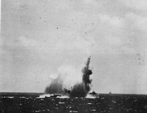
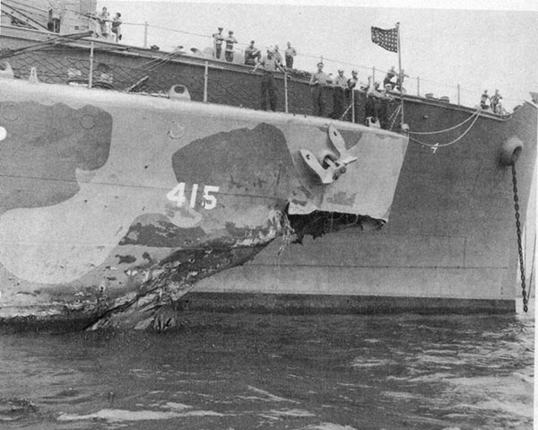
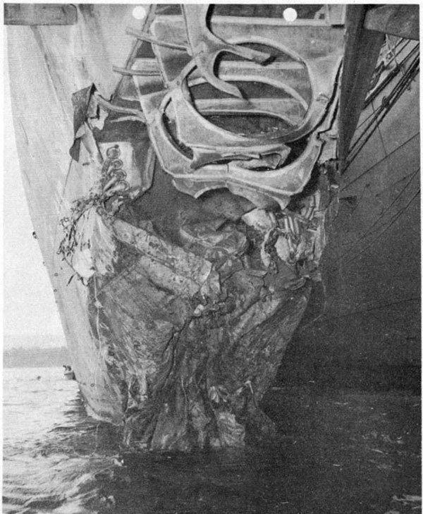
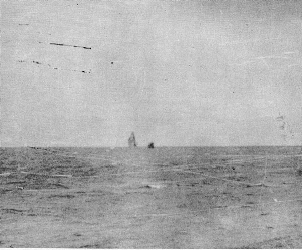
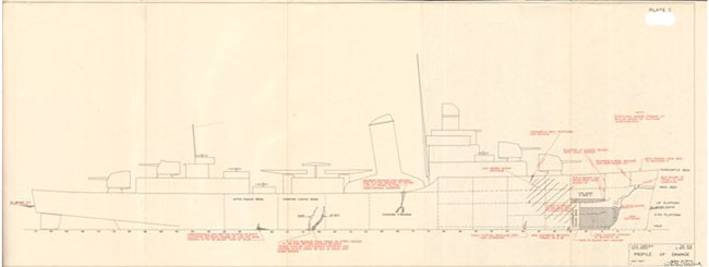
U.S.S. O'Brien (DD415)
Torpedo Damage
And
Loss
South Pacific
15 Sept. - 19 Oct., 1942
The Commander-in-Chief, United States Fleet and Chief of Naval Operations directs that this report be shown only to those persons to whom the report would be of value in the performance of their duties.
Steps shall be taken accordingly to insure that the report will be seen by those persons responsible for design, construction and repair of naval vessels, as well as for their operation, but by no others.
Preliminary Design Section
Bureau of Ships
Navy Department
24 June 1943
WAR DAMAGE REPORT No. 28
Printed By U. S. Hydrographic Office
U.S.S. O'BRIEN (DD415)
Torpedo Damage
and
Loss
15 Sept. - 19 Oct., 1942
| Class | Destroyer (DD415) | Length (W.L.) | 348'-3" |
| Launched | 20 October, 1939 | Beam | 36' -0" |
| Displacement (standard) |
1570 tons | Draft (trial) | 11'-6" |
References:
(a) C.O. O'BRIEN ltr. DD415/L11-1, Serial 028 of Sept. 23, 1942 (War Damage Report).
(b) C.O. O'BRIEN ltr. L11-1, Serial 01 of Oct. 26, 1942, (Loss Report).
(c) Comdr. Task Group 66.3 First Endorsement to reference (b), file No. A022/L11-1, Serial 001 of Oct. 31, 1942.
(d) Comdespac Second Endorsement to reference (b), File No. Lll-1, Serial 01078 of 17 Nov., 1942.
CONTENTS
| Page | |
| I - Summary | 1 |
| II - Narrative | 2 |
| III - Discussion | 8 |
| A. Miscellaneous | 8 |
| B. Analysis of Loss | 9 |
| C. Analysis of Repairs | 11 |
| D. Conclusion | 14 |
List of Photographs
| 1. | Torpedoing of U.S.S. O'BRIEN, 15 September, 1942. |
| 2. | Damage to bow resulting from torpedo hit between frames 1-6, port. Alongside U.S.S. CURTISS, 17 Sept., 1942. |
| 3. | Damage to bow resulting from torpedo hit. Alongside U.S.S. CURTISS, 17 Sept., 1942. |
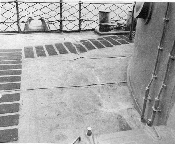
| 4. | Crack and wrinkle, starboard side, main deck, frame 78 caused by flexural vibration of the vessel as a result of the shock of torpedo detonation. |
| 5. | Wrinkles, starboard side, forecastle deck, frame 37 caused by flexural vibration of the vessel as a result of the shock of the torpedo detonation. |
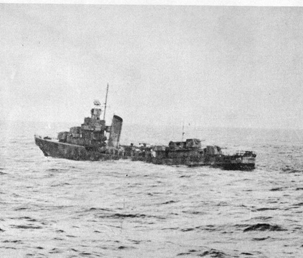
| 6. | At 0645, 19 Oct., 1942. Note permanent upward set of bow. |
| 7. | At 0750, 19 Oct., 1942. Heavy list to starboard. Breaking up process well advanced. |
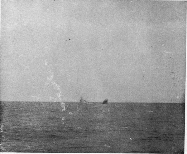
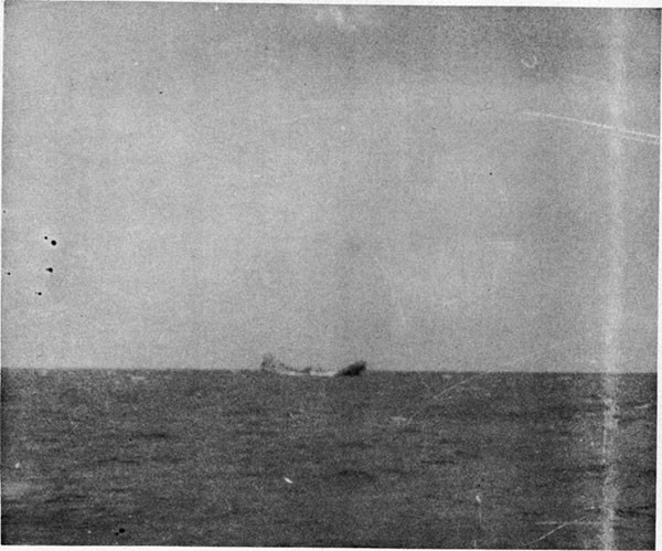
| 8. | At 0755-1/2, 19 Oct., 1942. Bow and stern sharply inclined. |
| 9. | At 0757, 19 Oct., 1942. Bow and stern apparently held together by main deck, piping and wiring. At 0758 O'BRIEN had disappeared. |
List of Plates
| I - | U.S.S. O'BRIEN - Profile of Damage. |
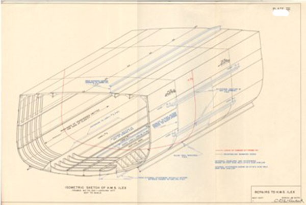
| II - | U.S.S. O'BRIEN - Reinforcing Structure. |
| III - | Repairs to H.M.S. ILEX. |
SECTION I. SUMMARY
1. O'BRIEN was torpedoed by a submarine during the afternoon of 15 September, 1942, while engaged in maneuvers as a unit of the anti-submarine screen for the aircraft carrier CURTISS and the Seventh Construction Battalion at BUTTON and by ARGONNE at WHITE POPPY. Upon completion of work at WHITE POPPY, decision was made to send O'BRIEN to Navy, Yard Mare Island, via Suva. En route to Suva, one light reinforcing plate, installed by ARGONNE, broke and, in addition, the rate of leakage which previously had been very low in the forward engine room, increased. These occurrences were not particularly impressive, but they did cause a thorough inspection to be made of the damaged structure and additional minor repairs at Suva. The inspection revealed no further apparent cause for alarm. Two days after leaving Suva, O'BRIEN broke in two and sank. The final failure of the structure occurred within a period of less than five hours.
3. During the interval between torpedoing and sinking, approximately 2800 miles were steamed. During the several voyages, no rough weather was encountered and speed of O'BRIEN never exceeded 12-1/2 knots.
4. The lack of drydock facilities at WHITE POPPY and BUTTON, advanced bases, was a major factor in the loss of O'BRIEN. Since that time, more officers experienced in construction and repairs have been sent to fleet operating areas. Drydock facilities have now been provided at both WHITE POPPY and BUTTON.
--1--
SECTION II. NARRATIVE
(All Photos and Plates I and II)
5. This report is based on the unusually complete data contained in the references. Photographs were furnished by the Commanding Officer of O'BRIEN and Commander Task Group 66.3. Plates were prepared by the Bureau.
6. During the afternoon of 15 September, 1942, two carrier task forces with HORNET and WASP were operating jointly in an area southeast of the Solomon Islands. Wind was about 14 knots and a moderate sea was running with no swell. O'BRIEN was a unit of the anti-submarine screen for HORNET. Recovery of planes by WASP had just been completed and task forces were maneuvering to regain base course and cruising formation. About 1452 O'BRIEN sighted smoke coming from WASP then distant 10,000 yards, one point on the port bow. General Quarters was ordered and the setting of Condition Affirm was started. HORNET task force started an emergency turn to the right. O'BRIEN slowed temporarily to avoid another vessel then ordered 25 knots and full right rudder. About 1454, while accelerating and swinging right, a torpedo wake was sighted two points forward of the port beam distant 1000 yards. This torpedo barely missed astern (about 4 to 5 feet) because of the accelerating speed and swing to the right. While attention was concentrated on this torpedo another wake was sighted close aboard (200 yards) to port on a collision course for the bow, O'BRIEN was thus bracketed by the two torpedoes (the first sighted had not yet cleared) and time did not permit further evasive action. It was hoped that the second would clear the stem, but this did not occur and the torpedo struck close to the stem on the port side.
7. The torpedo detonation is shown in photo 1. Photos 2 and 3 portray the small amount of local structural damage at the bow. Center of impact appears to have been just abaft the forefoot and possibly 10 feet below the waterline. The draft forward prior to damage was 11'-7". As shown on plate I, the bow structure below the main deck and aft to frame 10 was blown away. Framing and plating back to frame 14 were twisted and distorted. Free flooding occurred below the first platform between frames 10 and 22. Draft forward increased to 12'-2". A-202-L, on the first platform, flooded slowly to a depth of about two feet, the water entering through ruptures in the deck and bulkhead 14 as the bow plunged into the seas. Bulkhead 22 remained tight but was bulged aft. Bulkhead 25 was undamaged.
8. Severe vertical flexural vibration of the hull occurred. Although some buckling of hull plating and longitudinals occurred in the vicinity of frames 37, 78 and 123, some of which is shown in photos 4 and 5, the most serious failures were centralized across the bottom structure in the vicinity of frame 104. Here, as will be noted on plate II, the vertical keel, No. 2 deep longitudinals, No. 6 deep longitudinals, several smaller longitudinals and bottom plating all failed to some degree. The Commanding Officer reported that wrinkling and buckling of the shell and longitudinals, including the vertical keel, extended from frame 104 on the starboard side across to frame 108 port. The entire
--2--
bottom flange of the ship girder was thus seriously damaged. In addition, many rivets in this area were loosened or sheared. Considerable leakage into the forward engine room resulted through seams and rivet holes. The Commanding Officer reported that planes of the roller paths of the after 5" guns were depressed about one degree to port indicating that the after portion of the hull was twisted slightly to port.
9. Damage to instruments from shock was distributed throughout the vessel. Damage to individual instruments did not, however, appear to be particularly severe considering the violence of the shock and subsequent vibrations of the hull. Derangements are listed briefly below:
(a) Battery. All 5" guns were jarred or forced out of exact alignment with the director by either shock or hull distortion in both elevation and train. Height and other internal adjustments of the Mark XL111-7 stereo-rangefinder were distorted. The stable element was inoperative. The Mark I computer lost own ship's course automatic input. The cross level connecting rod to the FD radar antenna was bent. All tubes in the QC echo ranging equipment were broken.
(b) Engineering plant. One main circuit breaker tripped out. The oil sight glass on the port main thrust bearing carried away requiring the port engine to be stopped to allow insertion of a metal blank. The forward main air ejector suction line was cracked causing immediate loss of vacuum to five inches of mercury. Several light bulbs in the forward portion of the vessel were shattered although bulbs in pendant holders were undamaged. There were several grounds in the power, lighting and I.C. systems caused by shock and the deluge of water following the explosion.
(c) Miscellaneous. The master gyrocompass fell to the bottom of the binnacle, wrecking the compass. The SC radar antenna was thrown from the foremast wrecking the port pelorus as it went overboard. Insulators on main and emergency transmitting and receiving antennas were broken. Projectiles in the upper and lower handling rooms of the forward guns tore from their racks. Brackets holding spare part boxes on the bulkheads in the steering engine room were torn loose.
10. Damage control measures were undertaken promptly. Electrical power was cut forward of bulkhead 25. Two portable electric submersible pumps were rigged to pump out A-202-L. One burned out and the other had a ground which required two hours to bake out. The latter was then used to clear A-202-L of water. Nine thousand gallons of fuel oil were transferred from forward to after tanks decreasing draft forward to 11'-7". The first platform deck in A-202-L and bulkhead 25 were shored. The main circulator was started and put on bilge suction and flooding in the forward engine room was quickly controlled although the pump operated close to capacity. As many holes in the shell as were accessible forward and in the engine room were plugged.
--3--
11. Although it was undesirable to stop the port engine in submarine infested waters, it was essential that supply of lubricating oil be uninterrupted. When loss of lubricating oil suction occurred the port engine was held locked by the astern throttle and the lubricating oil pump stopped. A metal blank was inserted for the sight glass and new oil was run down. This operation was performed in 20 minutes. When vacuum in the forward condenser dropped to five inches of mercury the major source of leakage could not be discovered until the next day when a large crack was found in the expansion bellows of the air ejector suction line. The circuit breaker which tripped was immediately thrown back in. Power to the gyro was secured. Grounds in the electrical systems were rapidly cleared.
12. Repairs to the Mark I computer, the stable element and realignment of the battery were promptly made. Temporary lead-ins for radio antennas were rigged.
13. After the damage was incurred and while the damage control measures described above were in the process of execution, O'BRIEN proceeded under her own power at r.p.m. for 13 knots to BUTTON, a distance of 280 miles. Maximum speed over the ground was estimated at 12 knots. Wind and sea during passage were moderate with little or no swell. O'BRIEN arrived at BUTTON on 16 September and went alongside CURTISS.
14. O'BRIEN remained at BUTTON until 21 September. During this period O'BRIEN, CURTISS and the Seventh Naval Construction Battalion effected temporary repairs. Bulkhead 6 above the main deck, the main deck, the deck of A-202-L and bulkhead 14 between the first platform and main deck were all made tight by patching holes. Bulkheads 6 and 14 were reinforced with concrete. The deck of A-202-L and bulkhead 14 were also strongly shored. In addition, divers installed plug bolts and patches in the bottom plating of the forward engine room. All except two 600-pound depth charges were removed as were 150 rounds of 5" A.A. common. Finally, anchors and anchor chains were removed from the bow and stowed aft.
15. Upon departure from BUTTON, course was laid for WHITE POPPY, 600 miles distant, and O'BRIEN arrived on 23 September. Engine speed during the passage was for 12.5 knots but speed over the ground was only 11.5 knots. Again wind and sea never exceeded moderate intensity. O'BRIEN remained at WHITE POPPY until 10 October. During this period further repairs were accomplished by ARGONNE and ship's force.
16. During the two passages described above, O'BRIEN rode easily. Working of the forward and aft portions of the vessel with respect to each other was not observed although careful inspections and observations were frequently made. Repairs to the bottom at BUTTON by CURTISS were very effective in reducing leakage in the forward engine room. Only one fire and bilge pump was required to control leakage from BUTTON to WHITE POPPY whereas the main circulator, operating at near capacity, was required to control leakage prior to arrival at BUTTON.
17. At WHITE POPPY, ARGONNE executed further temporary structural repairs. At the stem a partial new bow section, extending down from the forecastle deck to half way to the waterline, was installed to protect against the force of seas when pitching.
--4--
At frame 37 on the forecastle deck, starboard, four vertical longitudinal flat bars were installed and the starboard sheer strake was reinforced by two partial longitudinals. At frame 77 three new sections of longitudinals were installed to replace the three cracked longitudinal girders under the starboard stringer strake of the main deck. In addition, tears in the sheer strake (apparently one on each side) were welded and two partial longitudinals outboard on each of the port and starboard stringer plates were installed. Finally, two partial longitudinals on the starboard sheer strake were added. Details of these repairs were not reported but they were apparently adequate as no further trouble was reported in these vicinities.
18. Details of hull repairs to the bottom structure, frames 103-109, in the forward engine room are shown on plate II. Attention is invited to the following features:
(a) Only partial longitudinals were installed. That is, fore-and-aft extent was only three frame spaces for all temporary members. Installation was made by welding longitudinals to the shell. Somewhat less than half of the replacement sections had the ends welded to adjacent web frames.
(b) Scantlings used were either about the same or larger than those of the longitudinals which each temporary member was to reinforce. There was no allowance, however, in the scantlings to replace the strength of the ship girder lost by the wrinkled bottom shell plating, including the flat keel.
(c) The partial longitudinals installed were offset transversely from the longitudinals they were obviously intended to reinforce.
19. In addition to structural repairs, O'BRIEN was further lightened while at WHITE POPPY by removing 11 torpedoes, 12,000 rounds of 20mm ammunition, eight 300-lb. depth charges, all SC radar equipment and the computer.
20. Upon completion of repairs at WHITE POPPY, O'BRIEN was considered capable of making 15 knots in a moderate sea. Mare Island was accordingly designated as the repair yard. At 0800 on 10 October O'BRIEN departed WHITE POPPY in company with CIMARRON and LANG. The group was designated as Task Group 66.3 with the Commanding Officer of CIMARRON as Commander of the Task Group.
21. After getting underway, a slow increase in the rate of leakage into the forward engine room was observed. This was not considered abnormal because of the many small patches and loose rivets in the underwater body. The Commanding Officer reported that a thorough check of the deflection across the damaged area showed that bending there was almost exactly the same as that across a similar undamaged length in the after engine room. Just how these observations were made was not reported, but ordinarily the problem of obtaining reliable hull deflection readings at sea is a difficult one. On the morning of the 13th of October, just prior to arrival at Suva, the reinforcing plate on No. 6 port deep longitudinal was found cracked, indicating a tensile failure. This 860 mile passage was made with turns for 13 knots attaining a speed over the ground of 12 knots. Wind and sea did not exceed moderate intensity.
--5--
22. Task Group 66.3 arrived at Suva on 13 October. While there, damage and previous repairs to O'BRIEN were thoroughly inspected. Except for the broken plate on No. 6 port longitudinal no other evidence of failure or weakness in the repairs previously made was discovered. The broken plate was repaired by welding an angle to it, apparently along the top.
23. Departure from Suva was made about 1430 on 16 October. Shortly after departure and when in the open sea, rate of leakage again increased but not alarmingly so as one fire and bilge pump was more than adequate to control the leakage. Wind and sea were still very moderate.
24. At 0000, zone minus 12, October 17, the date was changed due to crossing the international date line and the 16th was repeated.
25. By early morning of the 18th the rate of leakage had again increased to the extent that one fire and bilge pump had to be operated at high speed to hold the water level constant. At 0500 two pumps were put on in order that each might run slowly. At 0500 inspection revealed that the reinforcement of No. 6 port longitudinal had again cracked and the hull plating just outboard of this longitudinal had a three-inch crack along a wrinkle. These occurrences did not appear alarming but the Task Group Commander was notified. Rate of leakage continued to increase and by 0900 the main circulator was again put on bilge suction and the two fire and bilge pumps secured. About 1000, No. 6 port longitudinal and the damaged vertical keel were found cracked wide open. Cracks were developing in the shell under the main condenser and in the other damaged deep longitudinals and their reinforcing plates. Thus, the situation was progressively becoming more serious.
26. It was recommended to the Task Group Commander that O'BRIEN proceed to the nearest anchorage. At 1018 course was changed towards Pago Pago and to pass Upolu close aboard. All depth charges were disarmed by removal of pistols. Material Condition Affirm was set. About 1130 heavy topside weights were ordered jettisoned. These consisted mainly of the 5" loading machine, two anchors, deck winch, deck lubricating oil tank and torpedo after bodies and air flasks.
27. Rate of leakage continued to increase slowly. In the afternoon, although other conditions seemed unchanged, preparations were made for abandoning the forward engine room. As both main generators and the main switchboard were in the forward engine room, temporary leads were run to insure that the emergency diesel generator would keep the after engine room blowers and the electric auxiliaries of the condensing plant in operation. Main, auxiliary and bulkhead steam stops were closed about two-thirds. Emergency signals were arranged between firerooms and engine rooms and operating personnel were advised of the emergency procedure to be used.
28. Later in the afternoon the crew was assembled at quarters, advised of the seriousness of the situation and informed that LANG and CIMARRON had made adequate preparations for rescue. The Commanding Officer also informed the crew that he still expected O'BRIEN to reach port intact.
--6--
29. During the night hourly inspections were made. At 2300 the main circulator was running at half-speed. Two fire and bilge pumps were put on bilge suction and the main circulator was slowed to one-third. At 0100 on the 19th, conditions seemed unchanged. By 0200 rate of leakage had increased slightly. By 0300 there was still more leakage.
30. At about 0337 a shell plate on the port side behind the dynamo condenser cracked open with the noise of a pistol shot. Rate of leakage immediately increased and main circulator speed was increased to full. Water level still continued to rise slowly. Speed was reduced to nine knots. At 0339 speed was reduced to five knots and course was changed to lessen the working of the ship. At this time the sea was still moderate and force of the wind somewhat less than force four. The Task Group Commander directed O'BRIEN to further lighten ship and a large quantity of 5" projectiles, depth charges and additional torpedo after bodies and air flasks were jettisoned.
31. During the night the Task Group Commander debated the advisability of either CIMARRON or LANG taking O'BRIEN in tow as all vessels were prepared for this action. Decision not to take O'BRIEN in tow was based on the consideration that propeller thrust was desirable by virtue of tending to close the break, whereas towing would tend to open it. This opinion was shared by the Commanding Officer of O'BRIEN.
32. About 0402 course was again changed to close the nearest land. At 0410 water reached the auxiliary panel and main circuit breakers tripped out. Main generators were secured and the emergency diesel generator cut in. Water was five feet deep and rising. By 0430 heat made the forward engine room untenable and the starboard engine was secured and the engine room abandoned. At this time Upolu was only 40 miles to the southeast. Instructions were given to keep the port engine operating at all costs in an effort to reach Upolu and, at the same time, to maintain propeller thrust to reduce the tendency of the vessel to break in two.
33. The forward engine room flooded to the waterline. As this occurred, the after bulkhead of the after fireroom deflected forward. The after fireroom was then abandoned to prevent possible injury to personnel if the bulkhead collapsed. The forward fire-room supplied sufficient steam to the port engine to maintain the speed of five knots.
34. At 0600 the bottom suddenly opened considerably and the forward and after portions of the hull began to work independently. At 0605 the starboard side cracked open up to the main deck at frame 105. The two ends of the vessel were working severely. The main deck was still intact and pipe lines joining the two portions assisted in preventing complete rupture at this time. However, piping was working through the after bulkhead of the after fireroom which was flooding. At 0610 it was apparent that the situation was critical. All of the machinery plant was secured and abandoned. Hogging and sagging were violent and the two lower halves of the hull were alternately butting and parting.
35. At 0625 the main deck started to rupture on the starboard side at frame 105. O'BRIEN, with the approval of the Task Force Commander, was ordered abandoned. About 0630 all hands,
--7--
except the nucleus crew, went over the side. As conditions grew progressively worse decision was made by the Commanding Officer, and approved by Commander Task Group 66.3, to abandon O'BRIEN completely. This was completed by 0701. O'BRIEN was left equipped for towing.
36. It was hoped that one or both sections of the vessel would float and permit salvage. This was not the case. Photos 6 to 9 inclusive show the death throes of O'BRIEN. At 0746 both bow and stern took a sharp permanent upward set with the keel visible under gun No. 1 and the propellers clear of the water. At 0753 the vessel rolled slowly and deeply to starboard. It has slowly righted itself and, when upright, the main deck was awash amidships. The ends slowly folded together with bow and stern rising in the air and the hull as a unit slowly settling. At 0757 the stern went under, followed a little later by the bow. There were no explosions. O'BRIEN had steamed 1027 miles from Suva to the location where sinking occurred. Altogether a total distance of about 2800 miles had been steamed from the time of torpedoing.
SECTION III. DISCUSSION
A. Miscellaneous
37. The Commanding Officer reported that welding was excellent and that not a single weld failure was observed after the torpedoing. The shell of O'BRIEN was riveted throughout the middle portion of the hull. It is very probable that leakage into the forward engine room would have been much less had the shell been welded.
38. The Commanding Officer recommended that consideration be given to installing a valve at the bulkhead separating the engine rooms so that either or both main circulators could be used in case of necessity. The recommended change apparently would require the installation of a cross-connection line (with a bulkhead valve) between the copper bilge suction line in each engine room. War experience in destroyers has not yet developed the probability that such a cross-connection would be of value. When rate of leakage exceeds the capacity of one main circulator it is considered highly improbable that such flooding could be controlled by two. Even on O'BRIEN the use of two main circulators probably would have had little final effect. Furthermore, the evident disadvantages of piercing a main bulkhead with an eight-inch diameter line and changing from copper to galvanized steel in a salt water line (to preserve watertight integrity) must be recognized. At the present time the recommended alteration does not appear warranted. For destroyers with one engine room and for those with engine rooms separated by a fireroom the alteration is not applicable.
39. The performance of the engineering plant throughout the period of difficulty was nothing less than remarkable. All machinery continued in operation up until the time the forward engine room was abandoned because of flooding. The after engine room and forward fireroom continued in full operation until within less than two hours of sinking. Installation and alignment of turbines, reduction gears and shafts seems to have been excellent.
--8--
40. Although very little shock proofing and shock mounting of instruments had been accomplished on O'BRIEN, it is noted that shock damage to instruments was relatively minor considering the violence of the vibrations which followed the shock of explosion. The most important damage was the loss of the SC radar antenna and the tumbling of the gyrocompass. Almost all radar equipment is susceptible to shock damage although great strides have been made recently in providing shock proof mountings for equipment and sturdier foundations for antennas.
41. The jettisoning of heavy topside weight in time of emergency on small vessels is always sound practice. In this case, although stability was not a major consideration, it is probable that the articles jettisoned caused a slight reduction in stress, inasmuch as they were quite evenly distributed throughout the vessel.
B. Analysis of Loss
(Plate II)
42. Damage and impairment of longitudinal strength, by flexural vibrations of the hull following underwater explosions, have been reported in other cases of war damage. Loss of a vessel following opportunities for repair has seldom occurred.
43. Although details were not completely reported in the references, the data supplied by the Commanding Officer indicates that the entire bottom, including shell plating and keel structure, between bilge keels was damaged in the vicinity of frame 104. Estimates made by the Bureau on the basis that none of this structure remained effective as part of the ship girder reveal that the neutral axis of the section moved upward from 10.25 feet to 17.64 feet above the base line. This, in turn, means that the sectional modulus of remaining effective structure above the neutral axis was only 38% of the original sectional modulus to the main deck while the sectional modulus below the neutral axis was reduced to 7% of the original to the bottom of keel. It is obvious that the actual sectional moduli after damage were somewhat greater than these because some of the damaged structure was undoubtedly partially effective, but the above figures serve to emphasize the important decrease in longitudinal strength which occurred.
44. The above, then, approximated the condition of O'BRIEN when temporary repairs were undertaken at WHITE POPPY. Plate II shows the members installed. Calculations made by the Bureau for strength of ship girder after repairs were made and based on the further assumption that all members installed were fully effective indicate that the neutral axis dropped from 17.64 to 13.78 feet above the base line. The sectional modulus to the main deck increased to 85% and the sectional modulus to the bottom of keel increased to 42% of their respective intact values. It is probable that these figures are reasonably close to the actual values inasmuch as the assumption that all damaged structure was completely ineffective is balanced by the assumption that all reinforcing members were completely effective. With the ship in sagging condition on a standard wave of length equal to the length of the vessel and height from trough to crest equal to
--9--
one twentieth of the length, it is estimated that tensile stress in bottom wrinkled plating and longitudinals could approach 18 tons per square inch after repairs had been made and prior to flooding of the forward engine room. After flooding of the engine room and under the same wave conditions, tensile stresses in the same members could approach 21 tons per square inch. The variables involved in calculations of this type preclude accurate estimates. The figures given above, and those in paragraph 43, are indicative only of the changes in longitudinal strength which could have occurred rather than precise data on what actually occurred. As such, they serve to present the variations in degree of strength of the ship girder throughout the various phases of initial damage, subsequent repairs and flooding of the engine room.
45. Vessels of this class have high tensile steel hulls in which the ultimate strength approaches 35 tons per square inch with a yield point of about 22 tons per square inch. Medium steel was undoubtedly used for the temporary repairs. This has an ultimate strength of about 27 tons per square inch with a yield point of about 13.5 tons per square inch.
46. It is evident that O'BRIEN was fortunate during the passage to WHITE POPPY not to encounter even moderately rough weather. Even so, it is probable that additional bottom members were damaged by working of the hull. It is equally apparent that repairs at WHITE POPPY did not provide adequate strength for the ship girder for even the moderate seas which were encountered subsequent to departure.
47. Failure of bottom structure up to 0600 of the final day was progressive. Stress concentrations unquestionably occurred in the lower edges of reinforcing sections in way of the wrinkled plating. These resulted in early failure of at least some of them. Failure of some of the damaged structure then followed. Evidence of this progression is seen in the repeated failure of No. 6 port longitudinal reinforcing section, the small crack in the port shell at 0500 of the l8th, the crack in the keel at 1000 of the l8th and the constantly increasing rate of leakage. As depth of water increased in the engine room, tensile stresses in what structure remained must have correspondingly increased. During the period of rapid flooding (approximately one and one-half hours) some additional failures probably occurred. Finally, by about 0600, the engine room was full to the waterline and the hull was in a severe sagging condition. Any slightly uneven motion of the water could, at this point, cause a complete break of the remaining highly stressed members. This occurred shortly afterwards and the hull split open up to the main deck. The main deck, starboard, started to rupture but never completely failed. The end was imminent.
48. It has been demonstrated more than once that the stern section of a destroyer will remain afloat after the bow section is completely severed. Notable examples of this are HMS WOLFHOUND1 and our own SHAW2. This did not occur on O'BRIEN probably because the main deck never completely parted. As the vessel sank, the head of water imposed on the watertight bulkheads due to immersion of the midship section undoubtedly caused their collapse with subsequent progressive flooding of a large portion of the hull,
___________
1. Report issued by Bureau of Ships on 23 April, 1942.
2. War Damage Report No. 7.
--10--
both forward and aft.
49. Second guessing is easy. Yet some mention of the possibility of salvage of the stern half of the hull is in order. As noted in paragraph 48, it is a matter of record that the after half of the hull of a destroyer (WOLFHOUND broke approximately at the midship section) will float at a reasonable waterline and that stability is ample. By 0625 it was apparent that the hull, with the exception of the main deck, was completely severed. If burning equipment had been made quickly available for use there was a good possibility that immediate cutting of the main deck would have resulted in the salvage of the stern section, including the after engine room. As it developed, time was available for this operation. If the bulkhead separating the two engine rooms had been previously shored, the possibility of a successful tow to port would have been even further increased. In making these observations the Bureau is well aware of the extreme danger of such a cutting operation in the open sea and also of the chances against success. No criticism is, accordingly, intended or implied.
C. Analysis of Repairs
(Plates II and III)
50. To understand the problems involved in providing adequate longitudinal strength for the ship girder, it must be realized that all modern destroyers of the United States Navy are lightly constructed vessels. In the intact hull, adequate longitudinal strength is provided by the deck and shell plating augmented by longitudinals and deck beams. The longitudinals and deck beams perform a twofold duty; first, to provide strength as longitudinals and second, to reinforce the shell plating so that the latter will act effectively in strength. In view of the small amount of material involved in the ship girder (for a destroyer it totals less than four square feet in cross section) it is necessary to dispose the material favorably with relation to the neutral axis. For this reason the main deck, with its heavy longitudinals, and the bottom shell plating, with the keel and deep longitudinals, being farthest removed from the neutral axis, are the vital portions and are usually referred to as the "top and bottom flanges" of the ship girder. When damage of considerable transverse extent in the form of tension cracks or compression wrinkles in the vicinity of the midship section (the point of maximum stress) occurs, it is always critical and must be recognized as such. Thorough and extensive repairs, even though temporary, are always required.
51. With respect to O'BRIEN repairs it is evident that they were deficient in the following particulars:
(a) Not enough material was installed adequately to replace what had been damaged. Material which had been damaged in some degree totaled about 260 square inches in cross section whereas only material totaling about 100 square inches was replaced. From plate II it appears that in making repairs the area lost due to wrinkled bottom plating was overlooked and consequently was not replaced.
--11--
This omission not only increased the stresses because of the deficiencies in the replacement area, but the omission of lower flanges on the longitudinals or strips of plating under the longitudinals had the additional effect of concentrating stresses at the lower edges of the Tee sections in way of the wrinkled plating. This notching effect raised the stresses beyond the criticals, and cracks were probably started from these lower edges.
(b) The longitudinal replacements were improperly located. The replacement structures were not in line with the original longitudinals, neither were they of sufficient length and size to back up and distribute the loads properly. The eccentric arrangement produced high concentration of stress in the plating at the ends of the new as well as at the original longitudinals where the wrinkling started. Longer replacement longitudinals would have distributed the loading somewhat better, but, in this instance, with the sections used for the repairs, conditions would not have been improved sufficiently to alter the subsequent series of events leading to failure.
(c) Too much reliance was placed on the replacement of longitudinals. This was due apparently to a misconception regarding the part the plating plays in the strength of the ship girder. However, replacement sections of longitudinals must be installed, and when they are installed the following simple rules should be adhered to wherever practicable:
(1) The replacement sections must be extended to undamaged portions of existing longitudinals and plating.
(2) End connections to existing longitudinals should be effective. Welded or riveted end connections for the replacement sections must be ample in area to insure that the cross-sectional area of the undamaged portion of the existing longitudinals is carried across the damaged (wrinkled) section thus creating a continuous bridge between the intact longitudinals over the wrinkle.
(3) Replacement sections should be continuous and in the same longitudinal plane with existing undamaged portions of the longitudinals.
(d) It will be noted that at least the first and third of the above principles were violated on O'BRIEN. Replacement sections were only three frame spaces, or 63 inches, in length, and were offset transversely from the plane of existing longitudinals. They were, apparently, not tied in even to existing web frames inasmuch as they were reported to be only three frames in length, whereas adjacent web frames are located at frames 106 and 110. The discontinuity thus created must have inevitably resulted in stress concentrations, in the replacement sections far in excess of the ultimate strength in either tension or compression. Eventual failure was thus assured in even moderate weather.
--12--
(e) Additional smaller longitudinals, such as channels or even angles (with one flange down), placed at narrow intervals (6 inches, for example) along the girth of the wrinkled section and bridging the wrinkled section were not installed. These would have been very effective in replacing the strength lost by wrinkling of the shell plating and are recommended in the future where wrapper plates on the shell cannot be installed.
52. When it is impracticable to follow the clean-cut procedure outlined in paragraph 51 above, a careful survey of the situation should be made to insure that the emergency repairs do not introduce high stress concentrations. It is realized that adequate and temporary repairs to such damage without drydocking is a difficult problem. There is no easy way of solving it. The resort to the use of concrete as a reinforcing agent should not be overlooked. It lends itself to many variations of conditions and often provides a simple means of obtaining compressive strength. The tensile strength can be obtained by various means such as the introduction of strips of stiffened plating welded on the inside over the wrinkled hull plating. It is possible, in addition, to list the vessel about 15&geg; and install external longitudinals down to the turn of the bilge. In the event that simple measures cannot be utilized by virtue of the presence of obstructions in the bilges and bottom, such as piping, miscellaneous machinery, etc., sufficient time should be allowed to perform adequate repairs. When such circumstances are present, with a drydock not available but with the harbor in an area relatively immune from air attack - such as WHITE POPPY - it is recommended that sufficient time be allowed to clear the bilges by the removal of machinery and piping in order that proper repairs can be made. It is recognized that this will be a long and tedious job, probably running into months, but such procedure is preferable to running the risk of unnecessary loss of a valuable vessel.
53. It is impossible without docking to install wrapper plates on the bottom. Accordingly, longitudinals of sufficient size and number to make good the deficiencies in cross-sectional areas and sectional moduli resulting from the damage to bottom shell plates should be installed. In order to avoid stress concentrations, the longitudinals should have bottom flanges and contact with the shell, and should extend fore and aft over the undamaged portion of the shell a distance equal to at least four times the depth of the longitudinal on each side of the damage.
54. The case of HMS ILEX1, an "I" class destroyer of 1370 tons displacement, offers an interesting study with respect to repairs for impaired longitudinal strength. ILEX was bombed in the Mediterranean on 15 June, 1941, one 250 Kg. delayed-action bomb landing in the water 15 feet to starboard and slightly forward of amidships. It detonated under the starboard side approximately at 82 station. ILEX was making 24 knots. Flexural hull vibrations of considerable amplitude occurred. Local structural damage was almost nil but the hull flexures were sufficient to severely buckle the hull amidships. A deep wrinkle around the
__________
1. Being distributed to U.S. forces afloat.
--13--
girth from sheer strake to sheer strake was formed. The keel, for example, was indented a maximum of eight inches. ILEX was transversely framed with the vertical keel and two beams under each stringer strake constituting the only longitudinals of importance. The wrinkle was undoubtedly the result of compression failure caused by severe hogging of the hull. Evidence of this lies in the fact that, at drydocking, the bottom at the midship section was hogged upwards 18 inches.
55. It should be noted here that ILEX was lucky to have survived the long journey from Haifa to Durban, with stops at Port Said, Aden and Mombasa, inasmuch as temporary repairs, with the partial exception of those performed at Mombasa, were ineffectual in the extreme.
56. At Durban, very effective temporary repairs were made. The services of experienced personnel were available. Repair facilities included a drydock. Plate III indicates the repairs as completed for the journey from Durban to Charleston, South Carolina. The following should be noted:
(a) Beams installed were adequate in number and cross sectional area.
(b) Beams had sufficient length to provide continuity of strength. They were well secured to the hull.
(c) Particular attention is invited to the taper at the ends of the beams. Such a taper eliminates stress concentrations at the ends of the beams and is essential for external (as well as internal) longitudinals to prevent cracking from originating at these points. United States Navy Specifications require that tapered portions at the ends of longitudinals be two frame spaces in length. This is a safe rule to follow in effecting temporary repairs.
(d) The strength lost due to failure of shell plating was replaced by wrapper plates on the hull.
D. Conclusion
57. Loss of O'BRIEN constitutes a costly lesson. It was the first case in our Navy of structural failure amidships caused by a violent explosion far removed from the midship section. The unusual nature of the case undoubtedly contributed in some measure to the decision that the ship would be seaworthy for a long voyage. Duplication of the errors which caused the loss of O'BRIEN should certainly not occur if the lessons learned from the case are widely promulgated as it is expected they will be through the medium of this report.
58. Ordinarily, the lack of docking facilities is not easy to remedy. Fortunately, the need for floating drydocks sufficiently mobile to accompany the fleet to advanced bases was recognized some time ago, and an extensive program for construction of all sizes of floating drydocks was started. This program is now well advanced and the situation has been almost completely remedied insofar as the Pacific Fleet is concerned.
--14--
