
The Navy Department Library
USS Houston CL81
Torpedo Damage
Off Formosa
14 and 16 October 1944
CONFIDENTIAL
U.S.S. Houston (CL81)
Torpedo Damage
Off Formosa
14 and 16 October, 1944
The Chief of Naval Operations directs that this report be shown only to those persons to whom the report would be of value in the performance of their duties.
Steps shall be taken accordingly to insure that the report will be seen by those persons responsible for design, construction and repair of naval vessels, as well as for their operation, but by no others.
Preliminary Design Section
Bureau of Ships
Navy Department
15 March, 1947
WAR DAMAGE REPORT No. 53
Printed By U. S. Hydrographic Office
U.S.S. Houston (CL81)
Torpedo Damage
Off Formosa
14 and 16 October, 1944
| Class | CLEVELAND (CL55) | Length (O.A.) | 610 Ft. 0 In. |
| Launched | 19 June 1943 | Beam (Maximum) | 65 Ft. 7-1/2 In. |
| Displacement (Standard) | 10,000 tons | Draft (Mean Before Damage) | 24 Ft. 1-1/2 In. |
References:
(a) C.O. HOUSTON ltr. CL81/S88 Ser. 001 of 6 January 1945 (Damage Report)
(b) C.O. HOUSTON ltr. CL81/L11/A9-8 Ser. 003 of 20 January 1945 (Supplementary Damage Report)
(c) C.O. HOUSTON ltr. CL81/L11-1/L9-3 Ser. 0013 of 14 February 1945 (Supplementary Damage Report)
(d) Assistant Fleet Maintenance Officer's Memorandum to Maintenance Officer, Comseron 10 of November 1944
--i--
| SECTION | PAGE | |
| I | FOREWORD | 1 |
| II | SUMMARY | 2 |
| III | NARRATIVE | 5 |
| IV | DISCUSSION | 19 |
| A. Types of Torpedoes | 19 | |
| B. Structural Damage | 19 | |
| C. Analysis of Longitudinal Strength | 21 | |
| D. Machinery Damage and Reconditioning in the Forward Areas | 25 | |
| E. Buoyancy and Stability | 29 | |
| F. Miscellaneous Notes and Comments | 31 | |
| G. Conclusion | 35 |
I TORPEDO DAMAGE
II STRUCTURAL DAMAGE AND REPAIRS MIDSHIP SECTION
LIST OF PHOTOGRAPHS
| Photo No. | |
| 1 | Starboard side of bottom showing damage to hull. Note damage is confined between centerline and bilge keels. |
| 2 | Crack in E strake (5/8-inch STS) at frame 79, starboard, above hole in shell plating. |
| 3 | Port side showing wrinkles in shell plating at frame 74. Some plates were cracked in way of wrinkles, although not visible in the photo. |
| 4 | Crack in vertical keel (3/4-inch medium steel) at frame 74-1/2. |
| 5 | Looking up into forward engineroom. After end of condenser visible in right foreground. Base of No. 1 reduction gear visible on the left side of picture. |
| 6 | Horizontal wrinkles in starboard side of bulkhead 69 as viewed from forward fireroom. |
| 7 | View of No. 1 HP turbine in forward engineroom. |
| 8 | Damage to pinion of No. 1 reduction gear caused by oil spray nozzles dropping into gear teeth. |
| 9 | Buckled centerline stanchion in the forward engineroom. |
| 10 | Looking to starboard at after side of bulkhead 79 in after fireroom No. 1 shaft coupling is 5-1/2 feet aft and 3 feet above normal position. |
| 11 | Spring bearing for No. 1 shaft in after fireroom. The distortion of starboard shell plating in vicinity of frame 83 forced the bearing and shaft upward. |
| 12 | Buckling of No. 3 port longitudinal, under main deck, in compartment B-203-2L. |
| 13 | View of main deck over buckling of No. 3 port longitudinal shown in Photo 12. |
| 14 | Stiffener installed by ship's force en route to Ulithi. It is under No. 5 port main deck longitudinal, at frame 81. |
| 15 | Shoring in C-313-L on forward side of bulkhead 136. Note the use of side cleaning planks and fueling booms. |
| 16 | Damage to bulkhead 91 stuffing gland caused by No. 1 shaft when it slipped aft. View looking aft in after fireroom. |
--iii--
| Photo No. | |
| 17 | View of torpedo damage to starboard section of stern in drydock ABSD-2 at Manus. Note damage to rudder. Temporary above-water repairs were installed at Ulithi. |
| 18 | Looking outboard at damaged after section of hangar while en route to Ulithi. Note vertical split in shell plating and opening between the main deck and shell plating. |
| 19 | View of damage to the hangar space while en route to Ulithi. Note the upward distortion of the starboard side of the main deck. |
| 20 | Temporary transverse and longitudinal bulkheads installed in the hangar space by the ship's force at Ulithi. |
| 21 | Wrinkling of port main deck and shell plating at the stern. |
| 22 | The HOUSTON at Manus, 12 February 1945, ready for sea and the long voyage to the U.S.A. |
--iv--
SECTION I - FOREWORD
1. The record of HOUSTON, damaged by two Japanese aircraft torpedoes off Formosa in October 1944, includes much of unusual interest in the fields of warship design and practical damage control. The first torpedo struck and detonated against the bottom amidships, midway between the centerline keel and the starboard bilge keel while the vessel was listing to port during a high speed right turn. Thus, one of the few cases of the war involving under-the-bottom contact hits against moderately large warships is available for study.
2. A second torpedo struck HOUSTON while under tow two days after initial damage was incurred. Point of detonation was well aft on the starboard quarter, directly above the rudder. Although damage and flooding from this hit were in no sense unusual, an already difficult damage control situation was made worse, not the least of the additional problems so created being a bad gasoline fire.
3. The survival of HOUSTON, in the final analysis, was due in very large part to the damage control efforts of her personnel. In particular, the measures taken during the 43 hours which elapsed between the two hits so improved HOUSTON's precarious condition that she was able to survive the second hit and undergo the trip under favorable sea conditions to Ulithi.
4. Damage from the first torpedo resulted in the flooding of all four machinery spaces, thus immobilizing the vessel. Investigation reveals that this large extent of flooding was due primarily to the location of the point of impact, rather than to an unusually large or potent warhead charge as has been reported elsewhere. Structural damage to shell and inner bottom was moderate when compared to that received by many other cruisers which were torpedoed during the war, thus indicating a corresponding moderate weight of charge. The point of impact, in way of the forward engineroom, was approximately 24 feet from the forward engineroom bulkhead and 16 feet from the after bulkhead. Damage to both bulkheads was sufficient to permit uncontrollable flooding through them and is to be expected at these distances, even with moderate charges. The after engineroom flooded through leaks at the inboard end of the stern tube and around the bulkhead stuffing gland for No. 1 shaft. Damage at both places was caused by the shaft slipping aft by virtue of propeller drag - the reduction gear coupling in the forward engineroom having been broken by violent motion of the reduction gear, located directly above the point of detonation. Flooding of the after engineroom probably could have been controlled had normal drainage facilities been available.
5. HOUSTON's personnel submitted excellent and complete reports of damage and of damage control measures. In addition, complete descriptions of measures taken at advanced bases to restore the vessel to a condition satisfactory for her safe passage to Navy Yard, New York, were received. The ship's reports, supplemented by inspections of representatives from the Bureau, form the basis of this report. In general, the narrative follows that submitted by the Commanding Officer in reference (a).
--1--
SECTION II - SUMMARY
6. On 14 October 1944, HOUSTON was operating with a fast carrier striking force to the eastward of Formosa. At dusk, while engaged in violent evasive maneuvers, she was struck by a deep running aircraft torpedo during the course of a Japanese air attack. At the moment of impact HOUSTON was turning hard to starboard at 25 knots, the high speed turn giving her a sharp heel to port thus exposing the starboard side of the bottom to torpedo attack (See PLATE I).
7. The point of impact was at about frame 75 on the starboard side of the bottom approximately midway between the starboard bilge keel and the centerline keel. This location is directly beneath the starboard outboard propulsion unit (No. 1) in the forward engineroom. Also, it is about 16 feet from the after bulkhead and 24 feet from the forward bulkhead of the engineroom. Both bulkheads were damaged by the blast and fragments permitting both adjacent firerooms to flood rapidly. No. 1 shaft was broken at the coupling immediately abaft the reduction gear. Propeller drag pulled the shaft aft about 5-1/2 feet, damaging the bulkhead stuffing gland in the forward bulkhead of the after engine-room and also the inboard end of the stern tube. Leaks of major proportions through both the bulkhead stuffing gland and the stern tube resulted in the complete flooding of the after engineroom within about 30 minutes. The low pressure turbine in the forward engineroom was blown upward and it struck the third deck overhead with sufficient violence to open two scarfed joints in the armored deck (2-inch STS). The upward distortion of the deck damaged access trunks between the third and second decks to the extent that they were no longer watertight. Flooding on the third deck quickly covered an area bounded by bulkheads 69 and 101, a length of 128 feet. Eventually some shallow flooding occurred on the second deck as the ship listed to starboard. The ship came to a position of equilibrium with a list of 16 degrees to starboard.
8. With all main machinery spaces flooded and propulsive power lost, HOUSTON drifted, rolling sluggishly in the trough of the sea. Strenuous damage control measures were started immediately utilizing emergency and casualty power generators, but the situation remained doubtful. The precariousness of the tactical situation at this time combined with the hazardous condition of the ship, with HOUSTON rolling so heavily that her main deck dipped under at frequent intervals, led to the decision to abandon ship except for key personnel and a salvage party. Another factor entering into the decision was the realization that the total complement could not be properly fed and berthed aboard. Approximately one and one-half hours after this decision, detailed inspection of the damaged area and determination of the extent of flooding revealed that HOUSTON was not in immediate danger of sinking. Accordingly, the order to abandon ship was cancelled with some 500 officers and men still aboard.
9. During the night BOSTON (CA69) took HOUSTON in tow and began the retirement to Ulithi. Damage control measures, including the establishment of flooding boundaries, the dewatering of slightly damaged
--2--
and undamaged spaces and the jettisoning of some topside equipment were continued during all of the fifteenth and the morning of the sixteenth. It was during this 43-hour period that great improvement in stability characteristics was made by HOUSTON's personnel. By noon of the sixteenth all second deck compartments were dry and several third deck compartments had been made watertight and dewatered. HOUSTON was riding easily in tow.
10. During the early afternoon of the sixteenth a determined enemy air attack occurred during the course of which HOUSTON was struck by a second aircraft torpedo. This detonated upon impact well aft on the starboard side at about frame 145. The starboard aviation gasoline tank was destroyed and aviation gasoline was thrown throughout the hangar area. A gasoline fire of considerable proportions quickly engulfed the after portion of the vessel. Prompt and positive action extinguished this fire within 15 minutes with only the most modest of firefighting facilities. The effects of this hit on buoyancy and stability were not extensive compared with those of the first hit because the location of the point of impact was so far aft. Nonetheless, most of the buoyancy gained by the arduous efforts of HOUSTON's personnel since the first hit was lost. Stability characteristics also were reduced sharply, but the margin provided by the previous efforts was sufficient to prevent a second serious critical stability condition from developing. The situation, however, was precarious.
11. The lack of berthing and messing facilities required the transfer of additional personnel. Accordingly, request was made to the Task Group Commander to arrange transfer of 300 additional men to the accompanying destroyers. After the transfer had been accomplished, 200 officers and men remained aboard. These personnel turned to the tasks of controlling the additional flooding and eliminating as much free surface as possible. Despite other discouraging incidents during the long tow to Ulithi, unceasing work greatly improved HOUSTON's buoyancy, stability and longitudinal strength.
12. HOUSTON arrived at Ulithi on 27 October where HECTOR (AR7), ably assisted by the ship's force, executed emergency repairs under the supervision of representatives from Service Squadron Ten. No drydock at Ulithi was large enough to permit docking, but heavy structural repairs and considerable dewatering were accomplished prior to being towed to Manus. At Manus she was placed in ABSD-2 where the holes in the shell were patched, the ship dewatered, two boilers made operative and Nos. 2 and 3 main engines placed in operation. She departed Manus under her own power four months after being hit and arrived at Navy Yard, New York, on 24 March 1945. She was returned to active service on 6 October 1945.
13. Structural damage from the first hit is significant. Photo 1 shows the abrupt change in curvature at bulkhead 79 of the deformation of the bottom aft of the hole proper. Bulkhead 79, only about 16 feet from the point of impact, acted as a stiffener to the shell and inner bottom restricting deformation aft of that point. Damage to the bottom of bulkhead 79 is shown in Photo 10. It will be noted that the bulkhead was wrinkled sharply and torn loose at the bottom - indicative of the
--3--
severe attack upon it. Bulkhead 69, the forward bulkhead of the forward engineroom, approximately 24 feet from the point of impact, was not damaged as badly as bulkhead 79, as will be seen in Photo 6. Nonetheless, it was sharply crumpled and plating at the bottom was cracked. These cracks permitted uncontrollable flooding of the forward fireroom. In general, however, structural damage to the ship's bottom was not as extensive as has been observed in many cases of side contact hits.
14. At the time of the preparation of this report twenty months have elapsed since the war's conclusion. Seen with this perspective, HOUSTON's damage control performance was among the most outstanding of the war. The measures to improve stability characteristics, buoyancy and longitudinal strength which were executed by the ship's force while underway in tow were classic in planning and execution. The narrative to follow contains descriptions in some detail of these measures. In the discussion, the effects of each of the steps taken have been analyzed at some length.
15. Enhancement of longitudinal strength at Ulithi, re-conditioning of main machinery at Manus and accomplishment of temporary structural repairs, also at Manus, in all of which HOUSTON's personnel rendered highly effective assistance, are illustrative of the capacity and ingenuity of the repair organization which supported the Fleet in the forward areas.
--4--
SECTION III - NARRATIVE
(PLATES I and II and all Photos)
16. During the late afternoon of 14 October 1944, HOUSTON joined Task Group 38.1 which was operating off Formosa, replacing CANBERRA damaged the previous night. At 1630, a large enemy air group was detected at a distance of about 90 miles to the northwest. Carriers of Task Group 38.1 launched fighters to intercept them. At 1700, HOUSTON went to General Quarters as mixed groups of bogies and friendlies were in the area as close as 40 miles. At 1750, the carriers commenced recovering the interceptors and patrols as it appeared that the enemy attack had been repelled. Sunset occurred at 1822. The carriers completed recovering aircraft at 1825. The wind was 28 knots from the northeast, the sky overcast, and visibility 8,000 yards, decreasing. A choppy sea was running. At 1830 the Task Group, on course 135 degrees true, picked up a group of bogies closing from ahead. Speed was increased to 25 knots.
17. The attack developed rapidly. HOUSTON's 5-inch battery opened on enemy planes with radar control at 10,000 yards. At about 1841 a twin engine plane was detected visually to starboard at a distance of 2,000 yards, approximately 150 feet off the water. The forward starboard automatic weapons took the plane under fire and scored numerous hits. The plane then turned directly towards HOUSTON. At about 1,500 yards from the ship it dropped a torpedo and crossed over the bow. The Commanding Officer ordered full right rudder in an attempt to parallel the torpedo's course and at the same time to present the smallest possible target. The helmsman, either misunderstanding the order or failing to hear the order correctly due to the firing of all guns of 5-inch and smaller caliber, started the rudder left. The error was discovered immediately and corrected; however, due either to this delay or to the short torpedo run, the ship was hit amidships on the bottom at about frame 75. Another plane approaching from the port quarter dropped its torpedo from that angle, while a third torpedo was launched off the port bow. The above maneuver resulted in misses by the last two torpedoes. The plane which had dropped the torpedo to starboard remained under fire of the forward automatic weapons until it crashed off the port beam. Likewise, at least one of the port planes was shot down by HOUSTON.
18. The ship had a sharp list to port caused by the right turn at high speed. Thus, the starboard side of the bottom was exposed to the deep running torpedo which detonated against the bottom, about midway between the starboard bilge keel and the centerline keel. Had it been two feet deeper, the torpedo would have passed clear of the bottom.
19. The shock of the detonation, as felt in various stations on the second deck and above, was described as being accompanied by violent low frequency vibrations which whipped the hull. In the anchor windlass room a mooring line reel was thrown across the anchor engine, while one of the planes was jarred from its position on the catapult. The SK
--5--
radar antenna assembly fell from its pedestal and the after stay on the foremast carried away. Personnel in topside stations observed a dull flash from the engineroom ventilating blowers amidships; however, there was no fire. A column of water arose from the starboard side amidships. Columns of steam poured from both stacks. HOUSTON slowed, with all propulsive power lost, and soon was drifting.
20. All normal electrical power was lost. The after emergency Diesel generator, however, started automatically and provided emergency power for the after portion of the ship. The two casualty power Diesel generators, one forward and the other aft on the second deck, were started by repair personnel and provided casualty power.
21. Word was quickly received by the Commanding Officer that both firerooms and the forward engineroom were flooded and that the after engineroom was flooding despite efforts of personnel there to control it. The after engineroom was evacuated at 1910, some 30 minutes after the hit, when all efforts to control the flooding with submersible pumps proved unsuccessful. The ship listed to starboard and rolled violently in the trough with green water coming over the starboard deck edge. For some time after the hit the total extent of damage was not known. The Commanding Officer was informed that several third deck compartments were flooding and that a serious sagging condition appeared to be developing. At 2030 the latest information indicated that the ship was in a precarious condition and the Commanding Officer ordered abandonment to begin, as a necessary precaution and to better organize damage control work. Repair parties continued to explore the damage and at 2200 the Damage Control Officer, Gunnery Officer and Executive Officer, having made separate inspections of lower decks, reported that the ship was not in immediate danger of sinking. At that time, the Commanding Officer cancelled the order to abandon ship. During this period 719 men and 33 officers were transferred to three accompanying destroyers. Shortly after 2230, U.S.S. BOSTON took HOUSTON in tow and retirement to Ulithi commenced. During the night HOUSTON rolled violently, the roll at times reaching a maximum angle of 35 degrees to starboard. Permanent list, however, did not exceed 16 degrees to starboard.
22. The forward engineroom was opened to the sea by the hit and it flooded immediately. The forward bulkhead of this engineroom was damaged at the bottom which caused the forward fireroom to flood in approximately 10 minutes. All personnel escaped from the forward fireroom and boilers were secured by operating the valves from the third deck. The after bulkhead of the forward engineroom was badly crushed and ruptured, permitting the after fireroom to flood quickly. Only 17 of the 25 men in the after fireroom escaped, and of these, two died later from internal injuries. The majority of those lost appear to have been on the starboard side of the fireroom and were trapped as they attempted to open the armored hatch. Personnel stationed in the machine shop (B-307-L), directly above the forward engineroom, were knocked off their feet by the explosion. Of the 15 men stationed in this area, only 9 escaped, and one died later from steam burns.
--6--
23. Injuries to feet, ankles and legs caused by the shock of the explosion were remarkably few. Personnel stationed below decks had been trained to sit or lie down on the deck or if possible use lower bunks at their stations. This measure undoubtedly contributed to the small number of casualties.
24. The after engineroom reported water coming in around No. 1 shaft from the after fireroom and through a split in the stern tube. Damage Control Station ordered all portable submersible pumps to B-204-L and Repair IV began rigging these pumps to the after engine-room through escape scuttle 2-93-2. Power was supplied from the casualty power system. At 1850, the first pump was reported in operation, but at the rate the water was rising in the after engineroom, it was realized that flooding of this space could not be prevented. The after engineroom was evacuated at about 1910 and two of the three portable submersible pumps then in operation in that space were retrieved.
25. Personnel in the plotting room, on the second platform forward of bulkhead 57, and in the after Diesel generator room in the hold aft of bulkhead 101, were requested to inspect the two bulkheads for tightness and strength. This was done and the bulkheads (the flooding boundaries) were reported satisfactory. A portion of the ship's service telephone system was still operable at this time (less than 15 minutes after the hit).
26. Central Station (A-418-C), including Damage Control Station, soon lost communication with the rest of the ship. The 4MC circuits were useless immediately after the hit, the ship's service telephone system ceased to function in a short time and the sound-powered damage control circuit (2JZ) went out about 25 minutes after the hit. Efforts to clear the 2JZ circuit through the action cut-out box failed. Damage Control Station personnel then moved to Repair II in A-210-L on the second deck.
27. Flooding on the third deck was extensive. The armored deck (2-inch STS) was opened at seams above the forward engineroom on the starboard side and, as HOUSTON settled deeper, water rushed through these openings. Personnel escaped from the machine shop (B-307-L) and the evaporator room (B-306-E) through doors in bulkheads 69 and 79. Bulkhead 69 was in good condition and the watertight door on the starboard side was dogged. Bulkhead 79, however, was wrinkled at the bottom sufficiently to prevent dogging the door on the starboard side and B-313-L, between bulkheads 79 and 91, began to flood. Personnel evacuating the after fireroom used both the port and starboard trunks at frame 85, passing through them into third deck spaces. The escape scuttles at the top of the trunks in the second deck were not used because injuries to fireroom personnel did not permit passage through such small openings. These trunks, as are all trunks from machinery spaces in vessels of this Class, are armored with 3/4-inch STS to 3 feet 6 inches above the third deck. The upper portion is unarmored and this light plating was crushed by a small upward distortion of the third deck. As a result, the upper portion of the frames for the watertight doors in the trunks were so warped that the doors were not
--7--
tight. Despite efforts to close them, water rushing through finally forced the abandonment of B-313-L and permitted B-312-L to flood to a depth of 3 feet. Similar damage to the trunk (B-310-T) from the forward engineroom on the port side contributed to flooding of B-312-L and B-308-2E, as did damage to the door in bulkhead 79. PLATE I shows all doors, trunks and bulkheads which were involved.
28. Additional third deck spaces forward and aft of bulkheads 69 and 91 were subject to shallow flooding. This is shown on PLATE I. Plumbing fixtures and ventilating trunks in general were the sources of this flooding.
29. At one time, some 2 to 3 hours after the hit, water covered the third deck almost completely between bulkheads 38 and 101, a length of some 252 feet. Shallow flooding also occurred on the second deck in 5 spaces, as shown on PLATE I. In general, this water drained down from the main deck through leaky deck seams and two after hatches open for access to permit working parties to rig pumps to spaces below. It will be recalled that the main deck was almost continuously awash all during the first night. Removal of wood decking after arrival at New York Navy Yard revealed a diagonal crack in the plating between frames 65 and 70 and from about two feet inboard of the starboard shell plating to the centerline.
30. Third deck flooding was recognized both as the most serious menace to survival for stability reasons and as the problem which offered the biggest possible improvement in the condition of the ship in terms of labor expended. Accordingly, damage control efforts were concentrated on this deck, although other matters such as maintenance of casualty power, rigging for towing and restoration of firemain service were carried on simultaneously.
31. Compartment B-312-L was one of the first of the third deck spaces to be dewatered. Shores and wedges were used to force door 3-85-2 (leading into the uptakes space B-311-E) and door 3-85-4 (to the port trunk from the after fireroom) into place. When this was completed, water was three feet deep in the compartment. Portable submersible pumps then were able to control the flooding and eventually dewater the space, although leakage persisted through the bottom connections of the inboard longitudinal bulkhead.
32. Drying out of B-312-L made it possible to dewater B-308-2E (laundry) by removing the biggest source of leakage - that through the door in bulkhead 79 between the two spaces. Portable submersible pumps controlled the leakage through the bottom connections of the port inboard bulkhead (which separates the laundry from the evaporator room) and through the bottom of trunk B-310-T to the forward engineroom. Seeping deck drains in the laundry were troublesome but finally were plugged.
33. The water in the spaces forward on the third deck, A-312-L, A-313-L, A-315-L and B-303-L was removed, chiefly by bucket brigades, as opportunity permitted during the night. Flooding in these spaces originated through plumbing fixtures. Valves were tightened or blanked off as required.
--8--
34. Aft in B-316-L, between bulkheads 91 and 101, water was discovered flooding through the after engineroom ventilating trunks located in the scullery near the centerline. Welded connections of the trunks to the third deck, cracked by shock, and trunk access plates were leaking under the head of water (the waterline was about 6 feet above the third deck and the after engineroom was flooded completely). Deck drains in the scullery also were leaking. In addition, a leak in bulkhead 91 at the deck on the starboard side contributed to the dangerous situation developing in this large space. Water was more than a foot deep before the situation was controlled by caulking of leaks and shoring the trunks to reinforce them. While engaged in this work, the danger of opening additional seams and increasing the leakage through the ventilation trunks was present. Although the space was dried out and kept dry, so long as the after engineroom below remained flooded the space was in danger of flooding again.
35. The flooding that developed on the second deck shortly after the hit was an additional source of danger. As personnel from below deck stations went topside through the escape scuttle in the hatch at frame 106 on the starboard side of the main deck, water from the main deck poured down onto the second deck as the ship rolled to starboard. In addition, the leads rigged to pump out the space were initially through the starboard hatch. C-201-1L (bulkheads 101 to 113) flooded to a depth of six inches before the starboard escape scuttle could be secured and leads relocated to the port hatch at frame 106. Forward, as damage control personnel attempted to rig temporary communication lines from Repair II in A-210-L to the bridge through the escape scuttle in the starboard hatch at frame 47 and a door in the starboard side of the superstructure, water came over the starboard rail and flooded A-210-L six inches deep through these openings. These accesses were quickly secured and the lines re-routed through a port hatch. A small amount of leakage subsequently occurred through deck drains in A-210-L and C-201-1L, but this was easily controlled by bucket brigades.
36. In compartments B-202-L and B-203-L (between frames 69 and 91), seams in the second deck were loosened slightly by either blast or whipping of the hull. The subsequent pounding of the free water in third deck compartments below permitted leakage which required immediate attention. Oily water also bubbled up through a hole in the deck of B-202-L. The hole had been punched in the deck by a drill press in the machine shop below which had been thrown loose by shock and up against the deck. This hole was plugged using a mattress and shores. Rivet and seam leaks in the decks of B-202-L and B-203-L permitted oil and water to spread generally through these two spaces to a depth of about eight inches. Hatch 2-84 in B-203-L and doors 3-69-1 and 3-91-1 on the third deck were reinforced with shores. Shoring of the second deck from the overhead was then begun over compartments B-306-E, B-307-L, and B-313-L. The shoring of the second deck in this area consisted of a network of vertical stanchions to withstand the pounding of the water in the spaces below as the ship rolled. All the shoring material on board, including 14 side cleaner's stages, boat planking, beading and two fueling booms, was employed in this area. Photo 15 is typical of the methods employed.
--9--
37. Initial whipping of the hull, as noted in paragraph 19, was of appreciable magnitude. This was followed quickly by solid flooding of machinery spaces totaling 176 feet in length in the middle portion of the ship, placing the hull in a severe sagging condition. As a result, severe longitudinal strains occurred in the hull girder. These were manifested by popping of rivet heads in bulkhead 79, in the port longitudinal bulkhead of the uptakes spaces and in main and second deck plates amidships. Compression wrinkles developed in port main deck longitudinals and in the port stringer strake amidships. Photos 12, 13 and 14 show typical failures. Popping of rivets and groaning of the hull structure continued for more than an hour after the hit as HOUSTON was wracked by the sea.
38. During the hours immediately after the hit, when flooding on the second and third decks required so much attention and much of the ship was in darkness, the group of spaces in the hold and on the second platform between bulkheads 49 and 57 was neglected after immediate inspection revealed that bulkhead 57 (the forward bulkhead of the forward fireroom) was in good condition. Three hours later, 40mm magazines A-421-M and A-422-M were found to be completely flooded through cable stuffing tubes in bulkhead 57. Magazine A-424-M in turn flooded from A-422-M. Some eight other small spaces in this area were flooded partially through bulkhead cable stuffing tubes, bulkhead pipe fittings, etc. but not more than one foot in depth.
39. Dawn on the fifteenth permitted an accurate check of conditions aboard. Removal of water from the four spaces on the second deck had been completed by bucket brigades (all submersible pumps were employed on the third deck). Fourteen spaces on the third deck, extending generally between frames 38 and 101, and including seven main transverse subdivisions, were flooded, either completely or partially. The four main machinery spaces were flooded completely. Forward of the forward fireroom three small magazines were flooded completely and eight others partially flooded. Bulkhead 57 was found to have about a 4-inch deflection between the second and first platforms and above the first platform. This was surmised to be due to the head of water in the forward fireroom - a surmise later proved to be correct inasmuch as the deflection disappeared when the forward fireroom was dewatered at Ulithi.
40. The ship was still in a precarious condition, however. Drafts were 34 feet forward and 30 feet 4 inches aft with a mean of 32 feet 2 inches. These drafts correspond to a displacement of about 20,300 tons, thus indicating that about 6,400 tons of flooding water was aboard. The list was 12 degrees starboard with a freeboard of about 3 feet to the main deck amidships. HOUSTON was not rolling as deeply as she had during the night because wind and sea conditions were somewhat more favorable.
41. For the 500 officers and men remaining on board, it was necessary to provide drinking water, messing arrangements and toilet facilities. Morale aboard was exceedingly high and the Captain was able to send a report to the Task Group Commander that breakfast had consisted of "apple pie and ice cream," no meal having been
--10--
served since noon of the previous day. Drinking water was available in the three battle dressing station gravity tanks which were full when the ship was hit. These tanks were replenished periodically with fresh water ballast from A-507-V, A-508-V and A-901-V to A-908-V inclusive. This fresh water was by ordinary standards brackish and distasteful, but through careful rationing for cooking and drinking purposes it was adequate for the two-week passage to Ulithi; no additional fresh water was taken on board. Flushing water was provided by a bucket brigade, as insufficient power was available to operate the flushing pump en route to Ulithi. Bathing took place on the main deck with the assistance of a gasoline handy-billy and a fog spray nozzle. Casualty power from the casualty power generators was rigged to the ice machine and galley and later a crew's mess was set up on the main deck aft. An officer's mess was organized on the communication deck amidships. It was evident, however, that 500 men could not be properly cared for over an extended period with the facilities then available on board.
42. A sound-powered telephone system was rigged from the bridge with outlets on the forecastle, the four repair stations and in the steering engineroom. The bridge had steering control, the steering motor being supplied with power by the after 250 Kw emergency Diesel generator. The effect of the rudder on the position of the ship was negligible due to the reduced speed at which the tow progressed. The two 60 Kw casualty power Diesel generators located on the second deck, one forward at frame 40 and the other aft at frame 130, supplied power to the eight portable submersible pumps that still remained in commission. Serious leaks had been stopped during the night and by the morning of 15 October flooding was under control, although innumerable small leaks proved to be a nuisance.
43. Shoring of weakened bulkheads and decks continued, along with efforts to reduce seepage and remove free surface water from partially flooded compartments. Jettisoning topside weights on the starboard side was begun to reduce the list and gain freeboard. The transfer of liquids within the ship was not considered as a possible solution for the following reasons: first, wing tanks amidships were inaccessible due to extensive flooding; second, submersible pumps, the only means available for transferring liquids, were all in use; and third, the effect of such a transfer on the hull structure, already under a heavy strain, could not be predicted accurately.
44. Lack of ventilation, together with seepage, created a dampness in the atmosphere that made below decks spaces untenable for extended periods. For this reason, sick bay was moved to the cabin on the main deck and all hands ate and slept above decks. This dampness was the cause of electrical fires which broke out simultaneously during the early hours of 16 October in the steering motor power panel and in the after 250 Kw emergency Diesel generator distribution board. The fires were extinguished with CO2 before reaching serious proportions, but not before the power panel and distribution board had been put out of commission. The 250 Kw Diesel generator was secured and the ship proceeded under tow without steering control. This was the first of a series of electrical fires which plagued the ship during the two-week passage to Ulithi. It became evident that electrical equipment could not function properly unless the compartments containing it were properly ventilated.
--11--
45. During the morning of 16 October HOUSTON joined with CANBERRA (CA70), also proceeding toward Ulithi under tow. BOSTON passed the tow to PAWNEE (ATF74). This operation was delayed somewhat by difficulty in operating the windlass motor from the forward 60 Kw Diesel generator. The reduction in power of the Diesel engine possibly was caused by contaminated Diesel oil.
46. Dewatering of second deck spaces during the night of 14-15 October had restored a measure of stability so that fear of capsizing no longer existed. No large volume of water had been removed, however. Accordingly, dewatering efforts and jettisoning of topside weight were prosecuted vigorously to obtain some restoration of buoyancy and to reduce list (the main deck was still dipping under on the starboard side). At the same time shoring of second and third decks, doors and trunks was continued to insure the integrity of flooding boundaries.
47. During the fifteenth and the morning of the sixteenth third deck spaces A-312-L, A-313-L, A-315-L, B-303-L, B-308-2E, B-312-L and B-316-L were dried out. In addition, about 122 tons* of topside weight had been jettisoned. Displacement had been reduced to about 19,200 tons, a very significant gain of about 1,700 tons over the condition immediately after damage. List had been reduced to about 8 degrees to starboard.
48. Thus, by noon of the sixteenth HOUSTON's condition was greatly improved. She was riding in tow easily, rolling had decreased considerably and the main deck no longer dipped under. At 1200 the small group of ships was on course 130 degrees true, making a speed of advance of about 4 knots. PAWNEE and HOUSTON were to starboard, slowly drawing up to a position 2,000 yards abeam of CANBERRA and MUNSEE (ATF107). The accompanying cruisers and destroyers were in a circular air defense disposition about the tows, moving clockwise. HOUSTON's radar was inoperative but the TBS remained in commission. The wind was 15 knots from northeast, the sky was mostly overcast with high clouds, and the ceiling was about 10,000 feet. At 1340, a warning of approaching enemy aircraft was received. The pumping of A-421-M was interrupted at this time and Material Condition ABLE set. The 20mm and 40mm guns were manned. There was no power to the 5-inch and 40mm batteries, but the 40mm guns were operated manually.
49. At about 1348, several ships astern opened fire with 5-inch batteries in a direction away from HOUSTON. In the vicinity of their bursts a twin-engine plane, later identified as a NICK, was sighted bearing 300 degrees true heading directly for HOUSTON down the oil slick in her wake. When the plane had closed to about 5,000 yards, all 40mm guns that could bear opened fire. At about 3,000 yards, the plane dropped a torpedo at an altitude of 75 feet and continued on toward the ship, under heavy fire. The 20mm battery opened fire at about 2,000 yards. Many hits were observed and the plane flew up the starboard side at about 200 yards range, crossed ahead, lost altitude, and without burning, crashed into the sea about 3,000 yards ahead.
___________
* To attain this sizable total, 5-inch ready service from the starboard battery, the starboard catapult, two anchors with 5 fathoms of port chain and all starboard chain, the starboard motor whaleboat, two 36-inch searchlights, smoke generators, the port OS2U plane, about 25 tons of ordnance equipment and armored starboard doors from the upper levels were jettisoned.
--12--
50. The torpedo struck the starboard side at frame 145, having approached on a line parallel to No. 2 shaft. The hangar hatch cover, the airplane crane which was housed on the hangar hatch cover, and other structure were blown high into the air. A hole was blown in the bottom and side, extending from frame 138 aft and partially across the stern. The opening extended up the starboard side from the keel, tapering to about eight feet in width at the main deck level (Photo 17). Several leaks developed at the skeg, flooding void C-611-V. Compression failures occurred in the main deck plating and longitudinals aft of frame 129. Numerous wrinkles appeared in both the port and starboard shell plating aft of frame 120. The rudder was twisted and severely distorted.
51. At the time of the hit the starboard gasoline tank contained 2,500 gallons of gasoline, while the port tank was ballasted with salt water. The gasoline was blown up into the hangar and out through the hole in the stern where it blazed on top of the water. In addition, rags stowed in rag stowage compartment (C-423-A) were blown up into the structure aft of the hangar. These were soaked with gasoline and commenced burning. While handy-billies and foam generators were being rigged, CO2 bottles were brought up, opened and thrown into the blazing hangar. The actual effect of this CO2 on the fire was undoubtedly negligible, but the determination shown by the men who were fighting the fire in this manner stirred others to action. In less than 10 minutes foam was pouring into the hangar from three duplex proportioners, supplied by handy-billies. Two 2-1/2-inch hoses were rigged from the forecastle and the forward emergency electric fire pump was started. This procedure was followed to prevent any additional flooding of lower deck compartments by turning water into a firemain that might have been damaged by the explosion. One 2-1/2-inch hose, with a 12-foot fog applicator, was led aft on each side of the hangar and the fire was extinguished in 15 minutes. Minor fires recurred from time to time, but were quickly extinguished. By the morning of 18 October, the gasoline vapors had disappeared from the hangar.
52. Ten men manning guns on the fantail were blown over the side by the explosion. Of these, six were killed or missing and the other four were wounded. One man was killed and six others were wounded on board by falling debris.
53. The second torpedo hit also was accompanied by violent low-frequency flexural vibrations of the hull. As soon as the hangar fire had been extinguished, an inspection was made of the buckling in the amidships area. Further distortions were noted in previously buckled main deck longitudinals as well as the longitudinal bulkheads of No. 2 uptakes space. In addition, Nos. 3 and 4 main deck longitudinals, starboard, were found to be buckled amidships. A vertical crack had developed in No. 5 port main deck longitudinal (Photo 14). This subsequently was welded by the ship's force. Working of these damaged members was plainly visible as the ship rolled. Many vertical shores that had been installed previously on the second deck in the amidships area were jarred out of position. Nos. 5 and 6 main deck longitudinals, starboard, remained intact. Stringer plates and sheer strakes were inspected but were not observed to be damaged although a crack (paragraph 29) was later found when the ship was being repaired in Navy Yard, New York. Main and second deck plating was found to be wrinkled to various degrees throughout the ship.
--13--
54. Had the hit been farther forward, flooding would have been more extensive. It will be noted from PLATE I that all spaces aft of bulkhead 136 were flooded - the majority completely. The hangar and elevator pit were opened to the sea. The steering gear room below the hangar was almost undamaged, but a few rivets in the 2-1/2-inch STS overhead plate popped and the space flooded to a depth of about 4 feet from the hangar. Damage control personnel believed that many voids in the hold forward of bulkhead 136 were flooded but later only one, C-611-V, between frames 126 and 132, was found full. It was not possible to sound other voids. Forward on the third deck, the water in previously flooded spaces B-301-E, B-306-E and B-311-E, all on the centerline and extending from bulkhead 57 to 91, was found to have increased in depth about one foot. These three spaces were in open communication with machinery spaces below which had been opened to the sea by the first hit. After the second hit, HOUSTON changed trim sharply - from a condition down by the head to a trim by the stern - and this caused the increase in depth of water amidships. One of the most serious effects was the partial flooding of the after emergency Diesel generator room in the hold aft of the after engineroom, grounding out the generator. Water approached a depth of 2 feet in this space - entering through No. 2 shaft bulkhead stuffing gland in bulkhead 101. No. 2 shaft alley flooded completely via the stern tube. Finally, three small magazines aft on the second platform suffered minor leakage via fittings.
55. After the damage and flooding had been assessed it was found that drafts were 31 feet 6 inches forward and 32 feet 6 inches aft, with a mean of 32 feet. Oddly enough, mean draft was 2 inches less than it was on the morning of 15 October after the first hit. This was due to the flat shape of the stern aft and the large change of trim aft caused by the flooding from the second hit. List was reduced from 8 degrees to 6 degrees to starboard. The drafts after the second hit correspond with a displacement of about 20,300 tons, an increase of 1,100 tons of water. Thus, buoyancy gained since the first hit (some 1,700 tons) was largely lost by the second hit. Stability, although decreased somewhat by the second hit, remained satisfactory. These matters are discussed more fully in Part E of SECTION IV.
56. After the damage had been surveyed the decision was made to remove additional personnel to other ships in the formation. With HOUSTON under tow, personnel wearing life jackets, were ordered into the water in groups of approximately 100 to be picked up by destroyers that had taken station close astern. After approximately 300 men were transferred by this means, 48 officers and 151 men remained on board to continue salvage efforts during the remaining eleven days of the passage to Ulithi. These were divided into two groups. About 20 officers and 75 men comprised the salvage group. The remaining officers and men were organized into sanitation and messing details, ready, in addition, to assist with salvage work when required. The salvage group was divided into 3 parties, forward, amidships and aft. This proved to be a most effective organization for saving the ship. At times it was necessary to work all hands to the point of exhaustion, but this disadvantage was far outweighed by the simplification of the problems of berthing, messing and sanitation.
--14--
57. As darkness came on, the weather made up and rolling again increased until the starboard side of the main deck rolled under regularly. Working of the damaged longitudinals amidships began to increase and the pounding of the seas in the hangar placed a serious strain on bulkhead 136. Water seeped into compartment C-205-1L from the hangar through doors 2-136-1 and 2-136-5, which had begun to buckle. There was some doubt whether the ship would survive another night in this condition.
58. To save the ship the Commanding Officer decided upon the following course of action:
(a) Confine flooding and eliminate free surface. The first space to be dewatered was the steering engineroom, C-520-E, in order to make some use of the rudder. Rivet holes were plugged and the space pumped out, thus making it possible to use the hand hydraulic pump to center* the rudder. In conjunction, the flooded void beneath the steering engineroom also was dewatered. Leaks in the big storeroom, C-417-EA, were eliminated next and the space dried out. Central Station, A-418-C, was then dewatered, followed by magazine A-421-M. Other spaces forward and in the hold aft also were dewatered. Magazine A-422-M, on the port side, however, was left flooded to minimize the starboard list. Success of dewatering efforts is attested by the small list (2 degrees starboard), the mean draft of 31 feet 7 inches and the small drag (1-1/2 feet) upon arrival at Ulithi.
(b) Strengthen damaged longitudinals in the amidships area by the installation of "T" and box girder stiffeners. During the night, material and equipment were assembled and made ready to start cutting and welding at daybreak of 17 October. The girders were built up in place using 3/8-inch and 1/2-inch plates carried on board for damage control purposes plus plating cut from the superstructure. Acetylene torches were used to cut the plate, while a 200-ampere direct current portable welding machine was used in the installation of the stiffeners. Nos. 5 and 6 main deck longitudinals, port, were given first priority. The plates were cut by the torches and the girders were built up in place. Due to the working of the hull, difficulty was experienced in securing stiffeners to the damaged longitudinals; weld failures occurred and the work progressed slowly. After two days, however, a box girder was installed successfully on No. 6 longitudinal (See PLATE II).
(c) Reduce list and period of roll to prevent the main deck from rolling under to starboard. It was decided to move approximately 200 tons of 6-inch projectiles from the second and third shell decks to the lower handling rooms of their respective turrets. Jettisoning these projectiles was considered, but was discarded in favor of lowering the weight within the ship. All hands, officers and men, less those occupied with pumping, cutting, or welding went to work lowering the projectiles by hand. In spite of the heat, dampness, lack of ventilation and light, this job was completed by nightfall of 19 October. On the same day, after dewatering A-421-M, the ammunition in that compartment was jettisoned.
___________
* It was found that an indicated rudder angle of about 18 degrees starboard gave the easiest riding characteristics. At Manus the rudder was found to be badly warped, with the after section bent sharply to port (Photo 17).
--15--
(d) Install shores to reinforce weakened decks and bulkheads. Vertical shoring was reinstalled on the second deck amidships where it had been jarred loose by the second hit. The forward bulkheads of the hangar space (bulkheads 129 and 136) began to show signs of distortion at the third deck level under the pounding of the seas in the hangar. Although it was questionable whether the bulkheads would have failed, they were shored as a precaution. The section of the hangar deck over the port side of compartment C-417-EA began to sag slightly and was shored from below. Additional shoring material was obtained from ships in company to complete these jobs.
(e) Reduce fire hazards. The ship was a fire trap. In second deck living compartments, B-202-L, B-203-L and B-204-L, oil-soaked bedding and clothing lay on the deck. The atmosphere was warm and laden with oil fumes. There was no ventilation. Casualty power leads, electric pump leads and portable light circuits strung through these compartments were a potential source of electrical fires. After the oil-soaked clothing, bedding and furniture had been removed, these compartments were scrubbed down and a limited amount of ventilation was rigged. Electrical leads and junction boxes were secured to the overhead to reduce the possibility of short circuits.
59. On 20 October divers were sent into compartment B-313-L to attempt to close doors 3-79-3 and 3-85-1, but were unsuccessful.
60. The loss of buoyancy aft allowed the stern abaft frame 129 to sag slightly. Slight working of longitudinal strength members was noted in this vicinity and rivets in the second platform on the centerline in storeroom C-514-A, over flooded void C-611-V, began to pull through the deck. On 24 October a section of weld failed in an old temporary manhole in the deck of this storeroom, flooding the compartment. After the space was pumped out, the manhole was re-welded.
61. To provide a means of operating the drainage system for void spaces in the hold aft of frame 101, two portable submersible pumps were connected in series to a drainage system hose valve connection in the port shaft alley. This arrangement proved adequate for pumping normal accumulations of water from undamaged voids.
62. On 27 October HOUSTON arrived in Ulithi and made fast alongside HECTOR (AR7), port side to. Drafts at this time were 31 feet forward, 32 feet 6 inches aft, and the list was only 2 degrees to starboard.
63. Divers went into compartment B-313-L and succeeded in closing the doors in bulkhead 79 and in the trunk from the fireroom. Suction was taken with a 6-inch salvage pump, borrowed from a salvage vessel, and the space was dewatered. Though most of the oil had been skimmed from this space prior to pumping, a small amount still remained. Because of the oil which remained, however, the work required for cleaning was greatly increased. This experience, in the words of the Commanding Officer "convinced everyone that the great care exercised in removing oil from other compartments prior to dewatering saved a substantial amount of time and labor."
--16--
64. An investigation by divers revealed that a section of shell plating in way of the stern tube for No. 1 shaft was pulled away from the hull between frames 103 and 105. Blankets and Kapok life jackets were packed into the stern tube through this opening to seal the leak sufficiently to permit pumping out the after engineroom on 7 November. Suction was taken on the after engineroom and as the water level went down, bulkhead 91 was shored from the after side. Leaks around pipe lines and cables in the bulkhead were plugged. Leaks around No. 1 shaft at bulkhead 91 and the stern tube were sealed off with welded steel boxes.
65. Salvage work was interrupted early in November by a storm which caused extensive damage to the port side above the armored third deck. The deep draft of HOUSTON allowed the shallow draft camels to ride against the side of the ship midway between the second and third decks. Before HECTOR cleared the side, local wrinkling occurred in the port frames and shell plating between bulkheads 35 and 91. The shell plating split between frames 55 and 57, just above a side longitudinal. A temporary box was welded over this split which was replaced by a doubler on the outside of the hull. Prior to HECTOR coming alongside again, the wrinkled sections of the frames and bulkheads were cut out and replaced by temporary patches to conform to the contour of the damaged shell plating. The port side was then heavily shored to withstand the pressure of the camels.
66. Tears in bulkhead 69 were caulked from the after side by divers. As the forward fireroom was dewatered, bulkhead 69 was shored from the forward side. Dewatering was begun on 19 November. The tears in bulkhead 69 were then sealed off with welded steel cofferdams.
67. With approximately three feet of water remaining in B-306-E and B-307-L, preparations were made to seal off the damaged portions of the armored deck in B-307-L so that these spaces could be pumped out. Divers had reported the ruptured deck seams shown on PLATES I and II. Access was gained to B-307-L through the second deck escape scuttle into trunk B-309-T and through door 3-70 (PLATE I). Timbers were laid around the edges of the raised plates of the armored deck, shored into place and caulked. Deck drains in the evaporator room were caulked. These compartments then were dewatered, the operation being completed on 23 November. After securing the timbers with welded steel brackets around the damaged armor plate, the shores were removed and a steel box was welded around the edge of the damaged deck plating enclosing the break.
68. To regain some buoyancy in the flooded stern section, the ship's force tack-welded underwater a 1/4-inch steel bulkhead, six feet high, across the deck of the hangar at frame 138-1/2. After the forward section of the hangar was dewatered, welding of this temporary bulkhead was completed. A longitudinal bulkhead four feet high was installed amidships between the temporary bulkhead and bulkhead 136. An additional transverse bulkhead four feet high was installed to extend bulkhead 136 from the centerline to the port side (Photo 20). This separated the dewatered portion of the hangar into three sections and permitted more effective control of any flooding that might occur. This measure eliminated a considerable amount of free surface, eliminated the necessity
--17--
of strengthening the forward bulkhead of the hangar to withstand the force of the sea, reduced the danger of flooding compartments C-416-A and C-417-EA, permitted dewatering C-419-A and C-421-A and provided access to voids outboard of the steering gear room.
69. Storerooms C-419-A and C-421-A were filled with decomposed provisions. By sending divers into these compartments through hangar deck hatches it was found that the provisions could be floated out through these hatches and disposed of through the torpedo hole at frame 145 with very little effort. After these compartments had been cleared, the port and center sections of C-419-A were dewatered by sealing off the arch at frame 139 in the starboard longitudinal bulkhead outboard of C-420-E. The port section of C-421-A was similarly dewatered by sealing the non-watertight door at frame 146 in the port longitudinal bulkhead outboard and aft of C-420-E. Wooden cofferdams were built around the two hangar deck hatches to permit pumping operations in these storerooms. After dewatering had been completed, a hatch was installed in the deck to gain access to C-419-A from the forward section of the hangar. Other hatches and drainage facilities were provided aft for ease of access to spaces in the vicinity of the steering gear room.
70. To compensate for the loss of longitudinal strength insofar as possible, HECTOR, assisted by HOUSTON, installed four groups of three each of 24-inch built-up "T" beams (1/2-inch web and 3/4-inch flange) on the main, second and third decks, starboard, and on the main deck, port. These beams were continuous between frames 57 and 101 and located as shown on PLATE II. The installation was extensive inasmuch as the beams were very heavy and each was about 176 feet long. In order to tie together the three groups of beams installed on the starboard side so as to hold the decks and beams to their work, 8-inch and 6-inch pipe stanchions were installed on 12-foot centers on the "T" beams in way of each deep transverse web frame between the main and second, and second and third decks. Anti-tripping brackets were installed at the top and bottom of each pipe stanchion.
71. To provide a partial breakwater from following seas and as a means of strengthening the stern section, temporary side plating from the main deck to the waterline was installed in way of the large hole at frame 145 starboard.
72. HOUSTON departed Ulithi for Seeadler Harbor, Manus, under tow on 14 December. List was 1 degree starboard and drafts were 27 feet 2 inches forward and 27 feet 10 inches aft. The forward engineroom and after fireroom were still flooded, as were the hangar and various other small compartments. No. 1 boiler* was steaming for auxiliary purposes and the emergency evaporator in the after engineroom furnished sufficient feed and potable water for use during the passage. The after 250 Kw emergency Diesel generator was operating and furnished electricity for auxiliary purposes and lighting.
73. HOUSTON arrived at Manus on 20 December after an uneventful passage. On 8 January 1945, HOUSTON entered drydock (ABSD-2) for extensive temporary repairs and reconditioning. During this period in drydock, all flooded spaces were dewatered, Nos. 2 and 4 boilers and Nos. 2 and 3 main engines were placed back in commission. On 14 February, two days after undocking, HOUSTON held post repair trials, attaining a speed of 23 knots at 260 RPM on Nos. 2 and 3 shafts. HOUSTON proceeded to Navy Yard, New York, arriving 24 March 1945. She was returned to active service on 6 October 1945 after completion of permanent repairs and many authorized alterations.
___________
* Machinery reconditioning is described in Part D - SECTION IV.
--18--
SECTION IV - DISCUSSION
A. Types of Torpedoes
74. There were no reports of hydroplanes attached to the torpedoes - a late development of the Japanese with respect to aircraft torpedoes and one designed to give detonation beneath the target, rather than on impact. The damage, even that from the first hit, definitely indicates contact detonations of both torpedoes. The physical damage caused by each was consistent with a moderate-sized charge. Thus, the evidence points to the employment by the Japanese of their 18-inch aircraft torpedo identified in Bureau of Ordnance Pamphlet 1507 as Type 91, Modification 3, and fitted with a Type 91, Modification 3 warhead containing 522 pounds of Type 97 explosive (60 per cent TNT and 40 per cent Hexanite). This torpedo also can be fitted with a warhead containing 812 pounds of Type 97 explosive - but this large warhead was a late development and probably had not been issued for general service at the time HOUSTON was damaged.
B. Structural Damage
75. The first torpedo which damaged HOUSTON was an under-the-bottom contact hit, approximately at frame 75, only about 16 feet from bulkhead 79 and about 24 feet from bulkhead 69. The opening in the bottom into the forward engineroom was roughly 32 feet in length and 24 feet athwartships. Despite severe crumpling and splits at the bottom of bulkhead 79 (Photo 10), the bulkhead appears to have supported both the bottom and inner bottom plating and restrained distortion of the shell aft of that point. Bulkhead 69, located farther from the point of impact, was not damaged extensively, although it permitted uncontrollable flooding of the forward fireroom. Photo 1 shows the contour of damage to bottom plating and the abrupt change of curvature at bulkhead 79. The keel was hogged 14 inches and cracked (Photo 4). Wrinkles extended around the girth to the bottom of the port side armor belt, with some cracks in the shell (Photo 3).
76. The first hit and the hit sustained by CANBERRA during the same operation are the only cases of damage caused by under-the-bottom contact detonations which involved moderate-sized and larger U.S. warships during World War II. The physical damage in each case offers an interesting comparison with that caused by side contact torpedo detonations in the middle one-half length on other U.S. cruisers:
| Ship | Depth of Hit | Probable Charge Wt. |
Approximate Size of Hole in Shell |
| HOUSTON (CL81) | On bottom | 522 Lbs. | 32 Ft. by 24 Ft. |
| CANBERRA (CA70) | On bottom | 522 Lbs. | 36 Ft. by 25 Ft. |
| RALEIGH (CL7) | Close to, but above turn of bilge | 330 Lbs. | 36 Ft. by 25 Ft. |
| HELENA (CL50) | Close to, but above turn of bilge | 330 Lbs. | 35 Ft. by 25 Ft. |
| CHESTER (CA27) | 8 Ft. 10 In. below W.L. | 660 Lbs. | 48 Ft. by 25 Ft. |
| MINNEAPOLIS (CA36) | 10 Ft. 12 In. below W.L | 660 Lbs. | 34 Ft. by 25 Ft. |
| DENVER (CL58) | 7 Ft. 8 In. below W.L. | 660 Lbs. | 48 Ft. by 24 Ft. |
| PENSACOLA (CA24) | 6 Ft. below W.L. | 660 Lbs. | 48 Ft. by 36 Ft. |
--19--
77. Each case of torpedo damage to a warship has its own peculiar characteristics. The data given above, therefore, comprise only rough approximations and omit such matters as the restrictive influences of armor on PENSACOLA and DENVER, the odd distortion of the inner bottom of CHESTER and possible errors in charge weights. Thus, about all that can be concluded is that structural damage from HOUSTON's bottom hit was about the same as sustained by CANBERRA and somewhat less extensive than from side contact hits in the middle one-half length against other U.S. cruisers with torpedoes of roughly equivalent charge weights.
78. A reportedly severe hogging motion of the hull girder was produced initially by the detonation. This was followed by low frequency flexural vibrations of the hull apparently of considerable amplitude. The large quantity of water which flooded the four machinery spaces then created a severe sagging condition. The combined effects of these three phenomena resulted in localized buckling of shell plating, decks and longitudinals amidships (Photos 3, 12, 13 and 14). Longitudinal strength is discussed in some detail in Part C which follows.
79. The lower portion of bulkhead 69 was wrinkled and split intermittently in a horizontal plane (Photo 6). Structural damage forward of this bulkhead in the forward fireroom was restricted principally to minor distortion of several machinery foundations. The keel was hogged a maximum of 14 inches at frame 74 (Photo 1). The vertical keel (3/4-inch Medium Steel) was cracked at frame 74-1/2 (Photo 4). Several vertical centerline stanchions in the forward engineroom were buckled (Photo 9) by the upward distortion of the shell plating. Bulkhead 79 was extensively torn and wrinkled on the starboard side by the detonation and displacement of No. 1 shaft (Photo 10). Some distortion of the shell plating and machinery foundations occurred aft of bulkhead 79 on the starboard side in the after fireroom. Bulkhead 91 sustained negligible damage except in way of the stuffing gland of No. 1 shaft (Photo 16).
80. No. 1 L.P. turbine was thrust upward against the overhead of the forward engineroom with sufficient force to open a scarfed joint in the armored third deck (2-inch STS) in way of the machine shop B-307-L. This proved to be the most important source of flooding of third deck compartments. Previous war experience* has indicated that blast alone from deep hits is unlikely to cause rupture of an armored third deck. A notable case is that of HELENA (CL50)** whose third deck (2-inch STS) remained intact in spite of two deep torpedo hits in way of the machinery spaces.
81. The opening in the shell in way of the after hit was approximately 32 feet long and 28 feet in depth (Photo 17). The main deck was torn loose from the shell plating and pushed upward about four feet (Photo 21). Localized wrinkling occurred in the port shell and main deck plating (Photo 21). There were no wrinkles in either the decks or shell at the quarter-points as the result of either hit.
___________
* BuShips War Damage Report No. 54, CANBERRA (CA70).
** BuShips War Damage Report No. 43.
--20--
82. Perhaps the most noteworthy feature of the after hit was the protection afforded the steering gear room by the armor which surrounds it. The armor effectively prevented structural damage and derangement of machinery even though the point of impact was only about 20 feet from the starboard after corner of the armored box. The end plates of the steering gear box are 5-inch Class "B" armor; the sides are Class "B" armor tapered from 5 inches at the top to 3 inches at the bottom; the top is 2-1/4-inch and the bottom 3/4-inch STS plating. Unfortunately, however, the steering gear room eventually flooded to a depth of 4 feet through the rudder stuffing gland and leaky rivets.
C. Analysis of Longitudinal Strength
83. Because of the complete reports furnished concerning HOUSTON's structural damage, it has been possible to make an unusually thorough analysis of longitudinal strength. In the discussion that follows it is assumed that the ship is placed on a standard wave of length equal to the ship's length (600 feet) and height from trough to crest equal to one-twentieth of the length (30 feet). All calculations are for the sagging condition; i.e., with the hollow of the wave amidships - placing the main deck structure in compression and the keel and bottom structure in tension in the amidships area. This was done because stresses in the sagging condition were most critical after damage due to the great weight of flood water amidships.
84. Additional damage amidships as a result of flexural vibrations of the hull caused by the second hit as described in paragraph 53 was of insignificant amount when compared to that of the first hit. Flooding of the after spaces from the second hit was so modest in extent that it had but little effect on the bending moment amidships in the sagging condition. It was not sufficient, likewise, to create a bending moment amidships in the hogging condition of any additional critical significance. Accordingly, the critical condition which existed after the second hit was very nearly identical to that which existed after the first hit. For brevity, therefore, the discussion below will be confined to conditions after the second hit.
85. The standard wave on which the vessel is placed is assumed by designers to approximate the most serious sea condition, so far as longitudinal bending moment on the hull girder is concerned, that a ship generally may be expected to meet. It is therefore used to obtain an approximation of the maximum bending moments and the resulting maximum stresses which might be imposed on the hull structure under severe actual sea conditions. It is emphasized that stresses calculated in this way are for purposes of design and comparison only and are in no way indicative of actual stresses imposed on hull structures in smooth or moderate seas.
86. The scantlings of the hull structural members are so proportioned that the stresses in the top and bottom members do not exceed the design stresses. The design stresses are selected values, less than the yield strength of the ship's structural material by amounts sufficient to give suitable margins of safety, which shall not be exceeded in
--21--
longitudinal structural members when the ship, under normal conditions of loading is subjected to the longitudinal bending moments induced by placing it on a standard wave.
87. Properties of transverse sections of the ship's hull or girder which enter into considerations of the longitudinal strength are the horizontal neutral axis and section modulus. The horizontal neutral axis is a line parallel to the waterline through the center of areas of longitudinal structural members through the section. The moment of inertia of the section is calculated about the neutral axis and from the neutral axis distances to longitudinal structural members are measured to determine the section modulus. The section modulus is the moment of inertia of the transverse section with respect to its neutral axis divided by the distance from the axis to the most remote longitudinal structural member of the section. It is a measure of the strength of the section inasmuch as, with a given bending moment, the smaller the section modulus, the greater the maximum stress.
88. Damage to the amidships portion of a ship's hull below the water-line will generally result in increased bending stresses in the hull girder for two reasons. First, there will be a reduction in the effective cross-sectional area of longitudinal structural members leading to a smaller section modulus and, as noted above, a greater maximum stress. Second, flooding amidships will increase longitudinal bending moments in the sagging condition and therefore also increase the maximum stress. Thus, the bending moment imposed on the ship's structure by any given set of sea conditions would be increased in the sagging condition by the weight of flood water amidships and the amount of structure amidships resisting this increased bending moment would be reduced.
89. Prior to damage, HOUSTON was in a condition of loading approximating the full load condition. In this condition, undamaged and assuming the ship placed on a standard wave in the sagging condition, the tensile stress in the keel would have been 9.5 tons per square inch. This is the design tensile stress. The yield point in tension of the keel and associated plating (medium steel) is about 13.5 tons per square inch and the ultimate tensile strength is about 27 tons per square inch. The neutral axis is about 21.5 feet above the keel.
90. As a result of the two hits, a total of approximately 926 square inches of structural material amidships, about 24 per cent of the intact section (including damaged main deck stringers and deck longitudinals), was either destroyed or rendered ineffective. The damaged section is shown on PLATE II. Almost all of the damage, of course, was at the bottom of the ship girder. As a result, the neutral axis of the section shifted upward about 3.6 feet to a location approximately 25.1 feet above the keel. The section modulus to the main deck at frame 75 (the midship section) was only about 75 per cent of the original and the section modulus to the keel was reduced to about 53 per cent of that in the intact condition. It is therefore evident that the ship girder had been weakened seriously.
91. In addition, all four main machinery spaces were flooded completely, introducing some 4,500 tons of water into the hull with a center of gravity close to the midship section. Assuming the ship on a standard
--22--
wave, this quantity of water would have increased the bending moment at frame 75 from about 277,000 foot-tons in the intact condition prior to damage to about 426,000 foot-tons after the second hit - an increase of 54 per cent in applied bending moment in the sagging condition. Thus, the tensile stress in the keel of the damaged ship placed on a standard wave would have approached 23.7 tons per square inch - close to the ultimate strength and well above the yield strength of the steel. It is therefore evident that had HOUSTON met sea conditions approaching those of the standard wave her survival would have been doubtful. Fortunately, she was favored with moderate weather and sea conditions in her passage back to Ulithi.
92. En route to Ulithi, the ship's force fabricated and installed stiffeners for reinforcement of some of the buckled deck longitudinals. These are shown on PLATE II. Although aware that these repairs would not markedly reduce the stresses in the keel, the Commanding Officer and key damage control officers considered that such repairs would provide a slight margin of strength which might make the difference between the survival or loss of HOUSTON in the event of heavy weather. The manner in which the girders were installed is particularly noteworthy. All girders were properly tapered and each was of sufficient length to provide adequate continuity of structure. The repairs were the most extensive of their kind to be accomplished by a ship's damage control organization with the ship underway during the war. Analysis, however, reveals that these repairs replaced only 38 square inches or 4 per cent of the damaged structure at frame 75. This raised the neutral axis to 25.3 feet above the keel. The section modulus to the main deck was increased to 78 per cent, a gain of 3 per cent, and the section modulus to the keel was increased to 54 per cent, a gain of 1 per cent, of their respective intact values. The small increase in the section modulus to the keel had a correspondingly small effect (approximately 1 per cent) in reducing the tensile stress in the keel. After these repairs and with the damaged ship on a standard wave, the tensile stress in the keel at frame 75 would have been about 23.5 tons per square inch.
93. A total of twelve 24-inch "T" beams (3/4-inch flange and 1/2-inch web) were installed at Ulithi on the main, second and third decks as indicated in PLATE II. These were continuous from frame 57 to frame 101, a length of 176 feet. The addition of each "T" beam added 21 square inches of material. Twelve "T" beams thus represented a total of 252 square inches which raised the neutral axis from 25.3 to 26.4 feet above the keel. The section modulus to the main deck was restored to 91 per cent and the section modulus to the keel was restored to 58 per cent of their respective intact values. Tensile stress in the keel with the ship placed on a standard wave after these structural repairs were effected would have been about 22.5 tons per square inch, a reduction of about 1.0 ton per square inch.
94. It is well known that longitudinals close to the neutral axis are less effective as hull strength members than longitudinals remote from the axis. For example, the "T" beams on the second deck were only 44 per cent and those on the third deck only 10 per cent as effective in restoring the moment of inertia of the entire section as those installed on the main deck. The beams on the main, second and third decks were installed at Ulithi, however, as members of a deep box girder bridging the damaged area. Stanchions installed between the main and second, and second and third decks on 12-foot centers on the "T" beams in way of the main transverse web frames on the starboard side served to hold the main deck and "T" beams to their work, thereby forcing them to develop their maximum strength.
--23--
95. Likewise, the installation of longitudinal stiffeners above the neutral axis has only a small effect in increasing the section modulus below the neutral axis. In the case of HOUSTON, the section modulus above the neutral axis was increased 16 per cent while that below the neutral axis was increased only 5 per cent by the temporary repairs. However, since no drydock facilities were available at Ulithi, these repairs were the most effective that could be made under existing conditions.
96. In addition to the structural repairs effected at Ulithi, the forward fireroom, after engineroom, all third deck spaces and some spaces at the stern were dewatered. The reduction in bending moment with the ship placed on a standard wave effected by dewatering these spaces was such that upon departure from Ulithi tensile stress in the keel would have been about 18.8 tons per square inch, reflecting a reduction of 3.7 tons per square inch as a result of the dewatering and a total reduction of 4.9 tons per square inch or 21 per cent since the second hit.
97. It is re-emphasized that the calculated tensile stresses in the keel for the ship placed on a standard wave with the trough amidships in no way reflect actual stresses experienced by HOUSTON during the passage to Ulithi and from Ulithi to Manus - which actual stresses were only a small percentage of the calculated stresses - and are only included to indicate the relative effectiveness of the various measures undertaken to improve strength conditions and to illustrate the dangerous structural condition of the ship had it been subjected to severe sea and weather conditions. To recapitulate, the reduction in stress as a result of the measures taken to increase the structural strength and to reduce the flood water load amidships and assuming the ship placed on a standard wave would have been as follows:
| Tensile stress in keel after second hit | = | 23.7 tons per sq. in. | ||
| Stress reduction effected by structural repairs en route to Ulithi | = | .2 tons per sq. in. | = | 1 per cent gain |
| Stress reduction effected by structural repairs at Ulithi | = | 1.0 tons per sq. in. | = | 4 per cent gain |
| Stress reduction effected by dewatering at Ulithi | = | 3.7 tons per sq. in. | = | 16 per cent gain |
| Total stress reduction effected | = | 4.9 tons per sq. in. | = | 21 per cent gain |
| Tensile stress in keel upon departure Ulithi | = | 18.8 tons per sq. in. |
It is therefore evident that, of all efforts to reduce the stresses in the structure, the dewatering accomplished at Ulithi was by far the most effective due to the fact that replacement structure could not be advantageously placed. It is apparent that a very real improvement had been effected at Ulithi so that passage to Manus could be accomplished safely in reasonable weather.
--24--
D. Machinery Damage and Reconditioning in the Forward Areas
98. A torpedo hit on a cruiser in way of any machinery space other than the most forward fireroom almost inevitably will damage at least one of the shafts. The degree of derangement of the shafting primarily depends on the location of the point of impact with respect to the shaft. With HOUSTON the point of impact was directly beneath the propelling machinery for the starboard outboard shaft. The L. P. turbine was blown up against the third deck (2-inch STS) with sufficient force to open seams and permit flooding on that level (paragraph 80). No. 1 shaft was broken at the coupling abaft the reduction gear - the bolts either failing in tension or pulling through the holes in the flange. Drag of the propeller pulled the entire shaft aft about 5-1/2 feet and it came to rest with the forward coupling slightly aft of bulkhead 79 and about 3 feet above the normal shaft line (Photo 10). The forward pedestal bearing of this shaft, at frame 83 in the after fireroom, was raised about 3 feet by the upward distortion of the bottom (Photo 11) but remained reasonably intact.
99. Movement of the shaft destroyed the watertight integrity of the bulkhead stuffing gland in bulkhead 91 (Photo 16). As the shaft moved aft the coupling in the after engineroom moved aft until it struck the forward end of the stern tube, crushing it. Water flooded the after engine-room through these two openings. There was no damage caused by whipping of the shaft which could be identified as was the case with CANBERRA.* The two late Classes (CA139 and CL144) of U.S. cruisers have been equipped with a single face thrust bearing in the after spring bearing to provide some measure of protection against propeller drag. Thorough study of the problem over a period of many months demonstrated that other more rugged devices were so expensive in weight, space and complexity that their installation was precluded.
100. On 12 February 1945 HOUSTON was undocked after temporary repairs at Manus. At that time Nos. 1, 2 and 4 boilers and Nos. 2 and 3 main engines were operable. On 14 February 1945 post-repair trials were conducted prior to return to the United States. A speed of 23 knots at 260 RPM was attained. The two 60 Kw casualty power Diesel generators, the after 250 Kw emergency Diesel generator and two additional 75 Kw Diesel generators obtained at Manus furnished electrical power. Reconditioning of main machinery was a big job. As a matter of interest, descriptions of the reconditioning of No. 1 boiler and No. 2 main engine, typical of all of the work accomplished, are included below.
101. The forward fireroom had been flooded immediately following the first hit on 14 October, immersing both boilers. Fires in both were secured by the time water was about one foot in depth over the lower floor plates. The boilers were secured from the third deck. The main feed and check valves were left open. On 16 November, at Ulithi, the water level in the fireroom was reduced below the upper gratings. Personnel entered the fireroom at that time.
102. All exposed surfaces were washed down with hot salt water, followed by washing with hot fresh water supplied by HECTOR. A test of the water in the boiler obtained from the water gauge drain found it
___________
* BuShips War Damage Report No. 54.
--25--
to be salty, as expected. The boiler could not be dumped at that time because of the depth of water in the fireroom. The boiler remained full to the air cock by water backing up through the high pressure drains on the superheater. A hose was taken into the boiler uptakes through the inspection door and the inside of the breeching and the exterior surfaces of the economizer tubes were washed down with hot fresh water. This was followed by spraying with rust preventive compound, Grade A (Consol). External fittings also were sprayed at this time with Consol.
103. On 19 November 1944 the fireroom was dewatered completely. The firesides were opened and all boiler air casing doors removed. The firesides were washed out from the uptakes down to the furnace floor with fresh water. The tube banks and boiler fittings then were sprayed with Consol. All brick work was intact with visible damage limited to soaking with water and fuel oil. The chrome-ore was softened, with about a third of the studs exposed on the studded wall tubes. The outer casings were buckled badly in the rear of the boiler with several small holes through the casings. Tube exteriors were in good condition. Only one outboard economizer tube was slightly warped.
104. On 21 November, the boiler was drained, after completely isolating the high pressure drains from the forward engineroom. The boiler was then flushed out and filled to the air cock with fresh water. A hydrostatic test of 420 pounds per square inch was applied. Several leaks at the superheater handhole plates were found - but these were the only ones noted. On 22 November, leaks in the outer casing were repaired and the boiler was dumped. The watersides were opened, internal fittings removed and the steam and mud drums wirebrushed. There was evidence of corrosion in the steam drum, but no serious pitting. The tubes were found to be free of scale and pits.
105. On 24 November all superheater handhole plates were removed. A small amount of fuel oil was found in the last pass of the superheater outlet header. The superheater was flushed out with hot fresh water. The boiler watersides were closed and boiling out was started using 40 pounds of boiler compound per 1,000 gallons of water. Steam was provided through bottom blow valves and the superheater outlet drain. Boiling out was continued for 48 hours as prescribed in Chapter 51 of the Bureau of Ships Manual, frequent tests being made for alkalinity and condition of water.
106. After boiling out was completed on 26 November the boiler was washed out carefully. Internal fittings were replaced, watersides closed and the boiler filled to steaming level. Eight pounds of boiler compound were put in the boiler. On 27 November a wood fire was lighted to bake out the brick work and dry out the insulation. The superheater was kept full of water with the outlet header valve cracked. The fire was regulated so that a small amount of steam would escape from the air cock drain without building up pressure. On 28 November the fire was hauled and inspection the next day revealed that all brick work was dry. All tubes were sprayed again with Consol.
--26--
107. On 2 December a 750-pound hydrostatic pressure was applied using the emergency feed pump operated by high pressure air. The test was satisfactory. On 3 December fires were lighted under the saturated side using the smallest size of sprayer plates. One and a half hours were utilized to raise steam pressure to 200 pounds. The safety valves were lifted by hand and the boiler was then secured. Pressure to 400 pounds was raised on 4 December and the boiler cut in on the auxiliary steam line. This was repeated on 5 December, followed by two bottom blows to reduce salinity and hardness. Water tests showed 0.3 of a grain per gallon salinity. Four pounds of boiler compound were added, bringing alkalinity to 0.3 grain per gallon with zero hardness.
108. On 9 December fires were lighted to raise steam for setting safety valves. At 500 pounds pressure the safety valves were lifted by hand and then set at prescribed pressures. They then tested satisfactorily. After fires were allowed to die out, the boiler was given a bottom blow. On 11 December the boiler was in commission in all respects and steaming for auxiliary purposes.
109. Dewatering of the after engineroom started on 31 October, when the water level was reduced below the upper gratings. Reconditioning of Nos. 2 and 3 main engines was started on that date. The upper exterior surfaces of all machinery were washed down with hot salt water, this operation requiring about 2 days. On 2 November all gauges and thermometers were removed from No. 2 main unit and delivered to HECTOR for reconditioning. The inspection plates were opened on No. 2 reduction gear casing for inspection. This revealed some rust on the pinions and gears, but no serious corrosion. No jacking, however, could be accomplished until dewatering was completed. This was done on 4 November and, after cleaning and removal of debris, inspection plates of turbines and exhaust trunk were opened. There was evidence of active corrosion on the L.P. turbine rotor drum. Both H.P. and L.P. turbines were flushed thoroughly with fresh water. Next, Tectyl, Grade III, was sprayed under air pressure into each turbine through the inspection plates and also through the ahead and astern steam lines (throttles were open). The Tectyl formed a vapor which settled and condensed on all interior parts. Bridge gauge readings were taken and checked with previous readings which indicated no changes in height of journals.
110. On 8 November the lubricating oil sump of the reduction gear was pumped out, cleaned and wiped dry. At this time shortage of fresh water prevented flushing the sump. Sufficient Tectyl was placed therein to provide suction to the lubricating oil pump. An air drill was then coupled to the jacking gear. Two large-capacity gasoline-driven air compressors were obtained. It was then possible to jack the engine and operate the pump - permitting a thorough inspection of the reduction gears. All rust was stoned from the gears by 17 November. The Tectyl was pumped from the system to the settling tank for renovation. Two hundred gallons of lubricating oil were placed in the system, pumped through for two hours and then pumped overboard. Strainers were cleaned and 400 gallons of lubricating oil placed in the system. The engine was jacked with the lubricating system in operation, including the purifier. The strainers and the purifier were cleaned
--27--
frequently until all signs of rust and foreign matter were removed. From 17 November to 29 December the reduction gear was jacked daily for a period of one hour while work on the turbines proceeded.
111. The carbon packing was removed from the H.P. and L.P. turbines and the rotor shafts in way of the packing were found to be rusted and pitted. The shafts were cleaned and stoned - removing all of the rust, although some pitting remained. This was a tedious job on the completion of which the turbines again were sprayed with Tectyl, Grade III. The shafts were painted with Tectyl, Grade I, and the carbon packing was cleaned and stored since several weeks were to elapse before the engines could be tested. The forward bearing of the L.P. turbine was removed to inspect the journal which was found to be satisfactory.
112. On 10 December inspection plates were opened again on the L.P. turbine and some rust found. Both the H.P. and L.P. turbines were sprayed with Tectyl, Grade III. On 29 December the carbon packing was reinstalled.
113. Inspection in January 1945 revealed some pitting of the journals in way of the carbon packing. The packing was again removed and the journals stoned and painted with Tectyl. It was not replaced until just prior to admitting steam to the turbines for the post-repair trials.
114. Nos. 2 and 4 boilers received the same treatment as No. 1. Likewise, Nos. 3 and 4 main engines received the same treatment as No. 2. No 4 unit, however, was disconnected from the shafting and the propeller removed. No. 4 was in poor condition - having been immersed for 85 days. Also, it was seriously out of alignment. Although not used for the return voyage, proper treatment preserved it, permitting reconditioning and reinstallation at Navy Yard, New York.
115. In addition to the units described above, the necessary auxiliary machinery was reconditioned, including condensers, evaporators, feed pumps, etc. All told, more than 6,100 man-days of labor were expended on HOUSTON by the various repair activities at Manus. In the same period (i.e., 20 December to 12 February), HOUSTON's personnel expended approximately an equal amount of effort.
116. No. 1 main unit was damaged so badly that the H.P. turbine and the main condenser were scrapped. The L.P. casing also was scrapped although the rotor and diaphragms were retained and delivered to Navy Yard, New York, for reconditioning. The reduction gear was shipped to Navy Yard, Mare Island, for salvage. Shock broke off several oil spray nozzles and these damaged the gear teeth (Photo 8).
117. The removal of the major units for No. 1 main engine was hazardous. Most of them were adrift and the danger of their falling through the hole in the bottom of the shell into the drydock was always present. It was necessary to suspend them from the third deck with chain falls while the hull was cut away between frames 70 and 79. Suspension was a difficult rigging job, but was accomplished expeditiously.
118. The fireroom-engineroom-fireroom-engineroom arrangement of main machinery spaces of the CL55 Class, including HOUSTON, is more
--28--
vulnerable to underwater damage than the machinery plant arrangement on later cruisers. The vulnerability of the CL55 Class arrangement was realized at the time the layout was adopted. The demands of minimum work for plan development, speed of construction, minimum weight and rapid machinery procurement, however, dictated the arrangement provided. Four firerooms, instead of two, were considered seriously but would have necessitated a minimum increase in length of 16 feet, with a corresponding increase in weight of side armor and protective deck plating. For simplified plan work and ease of construction it was necessary to adhere as closely as possible to the dimensions of the previous class of six-inch cruisers,* the length of which was 600 feet.
119. Later cruiser machinery arrangements are of interest in this connection. The CA68 Class is provided with four firerooms, arranged from forward to aft with fireroom, fireroom, engineroom, fireroom, fireroom, engineroom. These ships, however, are 664 feet in length. The CL144 Class, also 664 feet in length, is provided with an arrangement similar to that of the CA68 Class. The CA139 Class, with four machinery spaces in line, each space containing a complete unit with boiler, engine, generator, etc., in addition has a 20-foot auxiliary machinery space separating the two forward spaces from the two after spaces. This reduces the probability to almost zero of complete immobilization of the vessel from a single underwater hit.
E. Buoyancy and Stability
120. Prior to damage, HOUSTON displaced 13,900 tons, which closely approximates Condition VI (full load) of the Inclining Experiment Booklet. In this condition of loading, HOUSTON had a GM of about 5.0 feet, corrected for free surface in the ship's tanks.
121. The slow flooding of the forward fireroom, after engineroom and B-313-L created a critical low stability condition, because of the extent of free surface. Later, when these spaces became full, stability conditions were much improved. But five minutes after the first hit, free water in partially flooded compartments reduced the GM to about a negative 1.9 feet. Complete flooding of the forward fireroom, after engineroom and 98 per cent flooding of B-313-L eliminated sufficient free surface to restore GM to about a positive 0.2 foot. The corresponding displacement at this time approached 20,900 tons. Action taken in pumping out partially flooded second deck compartments A-210-L, B-202-L, B-203-L and C-201-1L during the night restored GM to about 2.5 feet by 0700 on 15 October. The displacement had decreased to about 20,300 tons at this time.
122. The problems of improving GM, reserve buoyancy and eliminating the starboard list were vigorously attacked by the damage control organization. Further damage control measures during the fifteenth and morning of the sixteenth consisted of pumping out partially flooded third deck compartments A-312-L, A-313-L, A-315-L, B-303-L, B-308-2E, B-312-L, B-316-L and jettisoning about 122 tons of equipment. These efforts reduced the displacement to about 19,200 tons. The combined effects of reducing free surface and jettisoning raised the GM from about 2.5 feet to about 4.5 feet, an improvement of about 2.0 feet. Of this total increase on GM,
__________
* This was the CL49-50 Class which in turn resulted from modification of the CL40 Class.
--29--
about 1.8 feet was the result of elimination of free water, while the remaining 0.2 foot resulted from the removal of high weights.
123. HOUSTON's case is an excellent example of the effectiveness, in the event of extensive flooding involving a large number of compartments, of directing primary damage control efforts toward the establishment of flooding boundaries and the removal of water from partially flooded compartments. While jettisoning topside weight always improves stability, the degree of improvement is apt to be small in ships larger than destroyers because of the relatively small amount of weight readily available for the purpose. This was fully recognized by damage control personnel; however, all possible measures were taken to augment HOUSTON's chances of survival.
124. The survival of HOUSTON was due in very large measure to the efforts of her personnel during the 43-hour interval between the two hits. Recapitulating, when the condition of the ship stabilized after the first hit, GM was about 0.2 foot, displacement was about 20,900 tons, list was 16 degrees starboard and freeboard to the main deck amidships on the low side was about zero. At the time of the second hit, GM was about 4.5 feet, displacement was about 19,200 tons, list was 8 degrees starboard and freeboard amidships was about 4.0 feet. After the second hit, GM was about 4.0 feet, displacement about 20,300 tons, list about 6 degrees starboard and freeboard amidships about the same as before. It is apparent, therefore, that if the margins in stability, buoyancy and freeboard which existed at the time of the second hit had not been provided, the vessel would have been in a precarious condition, with a high probability of capsizing. As it was, she survived the second hit handily and was never in jeopardy as a result of that hit despite the loss of 1,100 tons of buoyancy and 0.5 foot of GM.
125. Chapter 4 of FTP 170(B) points out the danger of correcting the list on a ship suspected of small or negative GM by any means other than improving stability characteristics. Aboard HOUSTON this condition was recognized as evidenced by the actions taken to eliminate free surface and jettison or lower weight within the ship. All of these measures improved GM and at the same time decreased the list.
126. Had any attempts been made to correct the list by counterflooding, pumping liquids overboard or transferring them between tanks immediately after the first hit, it is quite possible that HOUSTON would have capsized. It will be recalled that ERIE (PG50)* capsized after transfer of liquids and weights while the vessel was in an unstable condition. RENO (CL96)**, upon being torpedoed, assumed a considerable port list. Soon after damage, a condition of negative initial stability developed. About nine hours later, after progressive flooding had occurred and certain damage control measures had been taken by the ship's force, the port list suddenly reversed to starboard. RENO was more fortunate than ERIE, for she reached a point of equilibrium at 16 degrees to starboard. All three cases involved a condition of negative GM at some time subsequent to damage.
____________
* BuShips War Damage Report No. 31.
** BuShips War Damage Report No. 55.
--30--
F. Miscellaneous Notes and Comments
127. Flooding of the steering gear room to a depth of four feet following the second hit drowned the steering motors. This space was the first to be dewatered thereafter and was accomplished with portable submersible pumps. The rivet holes were plugged and the rudder post stuffing gland made tight by welding a strongback over the gland and then setting up on the gland against the strongback. The hand hydraulic pump was used then to center the rudder and to assist in holding the ship easy on the towline. Later, it was found that 18 degrees starboard rudder was required to maintain a steady course while under tow.
128. Previous war experience had demonstrated the necessity of a reliable emergency source of steering power, particularly in the event of flooding of the steering gear room. The SALT LAKE CITY (CA25)*, with a comparatively obsolete type of steering gear, was provided with a Diesel engine in the steering gear room for the purpose. While the installation of the Diesel engine possessed several disadvantages and did not provide for the contingency of a flooded steering gear room, this interim installation also was provided PENSACOLA (CA24)** until a more satisfactory unit could be developed.
129. A remote-controlled emergency electro-hydraulic submersible pump unit has been developed since by the Bureau and has proved satisfactory in trial installations. This unit is now being provided all CV's, CVL's, CA's and CL's and may be used to control the rudder in the event of flooding of the steering gear room or casualty to the main source of steering power. Operation of the unit may be electrical by push button control in the steering gear room or remote, in the event of flooding, by push button control from the after gyro room on cruisers or from the Repair III station on carriers. If, in addition to flooding, power to the unit is lost, the pump may be operated remotely by mechanical hand-operated cranks from a deck above. This unit is in addition to the independent hand-operated pump previously provided in the steering gear room and to the chain hoists equipped with positioning blocks for positioning the rudder.
130. It is recognized that a definite need exists for an improved quick-opening armored hatch to permit the rapid escape of engineering personnel in the event of underwater damage. The design of such a hatch is a difficult mechanical problem which is presently under consideration by the Bureau. On CANBERRA, torpedoed in way of No. 3 fireroom, it was routine practice during General Quarters to secure some of the armored hatches leading to the machinery spaces with only two dogs. As a result, engineering personnel fatalities were a minimum. Rapid escape was made possible because the usual delay incident to releasing heavy dogs was greatly reduced. Some relaxation of watertight integrity is involved in this practice, but this was held to a minimum on CANBERRA by securely dogging the watertight doors and second deck escape scuttles of the vertical trunks between the third and second decks
___________
* BuShips War Damage Report No. 42.
** BuShips War Damage Report No. 35
--31--
which enclose the armored hatches. Protection from bombs, projectiles and other missiles from above the armored deck, of course, is provided with the hatch in place regardless of the degree of dogging.
131. The immobilization of both 250 Kw emergency Diesel generators and the main turbo-generators in the machinery spaces seriously threatened the scope of the salvage operations aboard HOUSTON. As a means of de-centralizing the main and emergency sources of power to some extent, the forward Diesel generator in the forward engineroom has been relocated to the first platform deck on the starboard side of compartment A-415-L. Although this is classified as a desirable alteration for all CL55 Class cruisers, lack of funds in the post-war period has precluded accomplishment on other vessels of the Class.
132. Flooding of any engineering space usually has short circuited both port and starboard cable runs, leaving casualty power cable as the only available means of distributing remaining power. The CA139 and CL144 Classes, now under construction, will have vertical as well as horizontal separation of main and alternate circuits. A more complete discussion of these improvements is included in the report of war damage to the DENVER (CL58)*.
133. Certain deficiencies in casualty power arrangements were noted by the Commanding Officer of HOUSTON. These included capacity of main risers, lack of risers from the after emergency fire pump and the steering motors and lack of circuit breakers for casualty power connections to vital machinery panels. Authorization to remedy these deficiencies on all cruisers had been issued in June 1944, by ShipAlt, but lack of availability at a Navy Yard had prevented their accomplishment on HOUSTON prior to damage.
134. The two torpedo hits destroyed all permanent main and secondary drainage installations. The task of clearing the flooded spaces proved to be an arduous one with the limited pumping facilities afforded by the remaining submersible pumps and gasoline handy-billies. Two 6-inch portable electric submersible pumps were borrowed from a salvage vessel and proved very valuable, leading to the recommendation that they be added to the allowance list. The weight involved, the availability of such pumps on salvage vessels and the addition of four P-500 pumps (a more flexible and portable unit) to the allowances for cruisers resulted in the decision not to provide the 6-inch pumps.
135. Progressive flooding through distorted bulkheads, hatches, trunks and watertight doors on the third deck level threatened the survival of HOUSTON. The main transverse bulkheads are carried intact to the second deck in cruisers subsequent to the CL55 Class. In addition, all access to vital spaces below the waterline is from the second deck and there are no outlets to third deck compartments from the access trunks. The above alterations, while desirable, cannot be accomplished on the CL55 Class cruisers due to the excessive weight involved and the difficulties of providing adequate access to existing second and third deck compartments.
___________
* BuShips War Damage Report No. 52.
--32--
136. Progressive flooding of compartments through bulkhead stuffing tubes for electric cable has long been a serious nuisance to ships receiving underwater damage. Leakage through bulkhead stuffing tubes, however, rarely has permitted complete flooding of a compartment. The most serious cases of such flooding occurred on DENVER (CL58)* and INDEPENDENCE (CVL22)*, where the damage control problems were complicated by such leakage. A complete discussion of the improvement in packing stuffing tubes and in watertight construction of electrical cable is included in the War Damage Report for the above vessels.
137. The efficiency and durability of the present 2-1/2-inch portable electrical submersible pumps has long been a controversial subject. While these pumps played a large part in saving the ship, HOUSTON personnel experienced some difficulty because several of the pumps burned out under heavy load in attempting to pump heavy oily mixtures of fuel oil and water. A group of pumps from various manufacturers were service tested by the U.S. Naval Engineering Experimental Station, Annapolis.** Results of the tests indicated that all submersible pumps with 5 H.P. motors will pump oily mixtures without undue difficulty. The tests emphasized, however, that submersible pumps with 2-1/2 H.P. motors, manufactured by the Northern Pump Company, do not have proper head-capacity characteristics to pump such mixtures. Again, the practice of using the electric cables as handling lines will insure a premature failure of any model. If a single pump will not develop sufficient discharge pressure, two submersible pumps should be operated in series. HOUSTON made use of this arrangement in pumping out compartments abaft frame 101.
138. HOUSTON was provided with 2-1/2-inch submersible pump discharge fittings in the shell at various locations. These proved of great value in dewatering operations. The installation of such fittings was authorized with some reluctance because of the menace to watertight integrity in the event caps are not in place at the time of damage. HOUSTON had no difficulties from missing caps and the fittings fulfilled the purpose for which they were installed.
139. HOUSTON's heavy duty 300 ampere D.C. welding machine in the forward engineroom was not available after damage. The two portable A.C. welding machines were used although their capacity was so small that considerable difficulty in executing structural repairs was encountered. A 200 ampere D.C. machine in the shipfitters' shop proved to be the most valuable. Personnel were reluctant to attempt underwater welding with the A.C. machines. As a result, the Commanding Officer recommended that the A.C. machines be replaced with D.C. machines. If safety precautions are followed, A.C. can be used safely for underwater welding. These precautions were promulgated again, after receipt of HOUSTON's recommendation, in BuShips ltr. QP/W§C-(2)-(6)(692-660)EN28/A2-11 of 12 January 1945. Later cruisers, however, are provided with two 200 ampere D.C. portable welding machines and HOUSTON's allowance was so modified during her repair period.
__________
* BuShips War Damage Report No. 52
** Complete test results were reported in BuShips Bulletin of Information No. 19, 1 July 1945.
--33--
140. The possibility of a break in the firemain aft of the after emergency fire pump, with the accompanying danger of additional flooding, precluded use of the after main in fighting the fire in the hangar space and forced the laying out of long leads of fire hose from forward plugs. An additional fore and aft main on the second deck is being provided the CA139 and CL144 Classes. Weight considerations prevent the addition of an upper main on earlier cruisers.
141. HOUSTON encountered considerable difficulty with the drainage system in dewatering and keeping the steering gear room dry. The drainage system in this space was altered during the repair period and three of the four existing deck drains which emptied into the void below were eliminated. The remaining deck drain, fitted with a stop check valve, will remove water which leaks from the rudder post stuffing box. The accumulation of water in the void below is to be removed by the main drain connection to this space. The 350 gpm drain pump in the steering gear room has been provided with a well, foot valve and priming line to facilitate emergency drainage of the steering gear room.
142. HOUSTON reported rapid deterioration of electric motors in unventilated compartments, particularly in spaces containing the emergency fire pumps. As a means of overcoming this difficulty, four 1000 Kw heaters were authorized initially for the Class in the spaces containing the emergency fire pumps. It has since been found that these heaters are unnecessary if the motors and fire pumps are operated for several hours every week.
143. The need for an increased number of RBA's (Rescue Breathing Apparatus) was demonstrated again during the salvage operations. The allowance for 10,000-ton cruisers was increased from 48 to 96 in January 1945.
144. The gasoline fire in the hangar never was permitted to assume dangerous proportions as a result of the prompt action taken. The starboard tank C-613-Gas was badly damaged and 2,500 gallons of gasoline was blown throughout the hangar. It is interesting to compare this case of war damage with BIRMINGHAM (CL62)* in which a skip-bomb struck the starboard counter. In the latter case, C-613-Gas, containing 3,500 gallons of gasoline, was opened to the sea, but no fire resulted. The primary difference between the two cases lies in the facts that the gasoline on BIRMINGHAM flowed astern out of the damaged tank, while on HOUSTON it inundated the hangar and adjoining spaces.
145. Inspection of the rudder at Manus disclosed that the after section was distorted badly (Photo 17). It was found to be warped about 20 degrees. Despite such damage it will be recalled (paragraph 58) that it was effective during much of the long tow to Ulithi, and later, to Manus, although it was necessary to carry a recorded rudder angle of 18 degrees starboard to maintain a steady course.
__________
* BuShips War Damage Report No. 48.
--34--
G. Conclusion
146. HOUSTON adds one more case to the record of ships having negative stability at some time subsequent to damage. The great effectiveness of eliminating free surface and the relatively minor effectiveness of jettisoning topside weights in improving stability are again demonstrated.
147. HOUSTON's structural strength amidships was seriously reduced. In this case the large bending moment induced by an unprecedented length of flooding amidships would have been a major factor contributing to the high stresses which would obtain under severe sea conditions. Advantageous disposition of replacement structure on both sides of the neutral axis could not be accomplished at Ulithi because of lack of drydock facilities. Therefore dewatering of spaces to reduce the bending moment was the most effective measure taken to reduce possible stresses in the hull girder during the passage to Manus.
148. Though some of the damage control measures were not as effective as others, it is emphasized that each step taken resulted in an improvement of the ship's condition. Coordination of effort insured that nothing which would improve the situation was neglected, no matter how small the improvement appears in retrospect. The cumulative effect of all measures resulted in the restoration of HOUSTON's inherent ability to survive.
149. As in the case of CANBERRA, the extensive flooding which resulted in the loss of all propulsive power and left operating personnel with an exaggerated impression of the potency of Japanese torpedoes was caused partially by the distortion and movement of a propeller shaft.
150. That HOUSTON survived two torpedo hits which produced a precarious stability condition, extensive flooding, serious loss of structural strength amidships and a severe gasoline fire is due for the most part to the intelligent approach of her personnel to the damage control problems with which they were confronted and the skill and perseverance with which they carried out the control measures initiated.
--35--
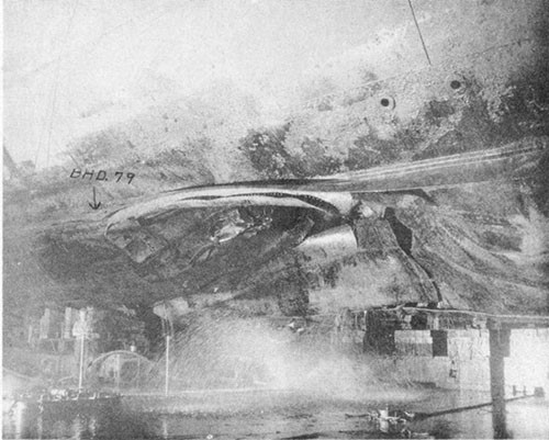
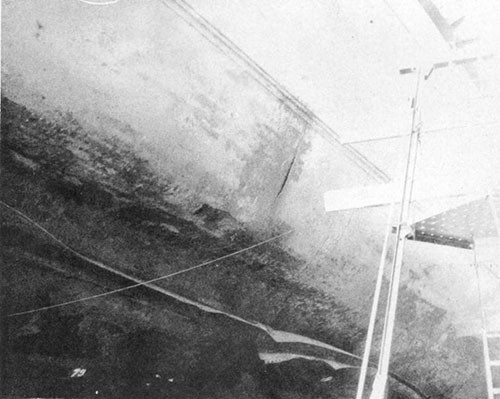
--36--
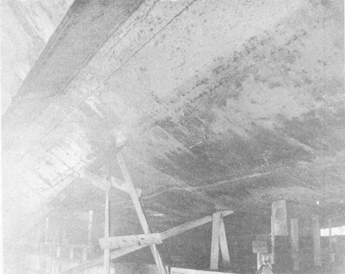
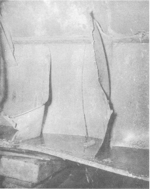
--37--
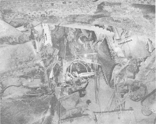
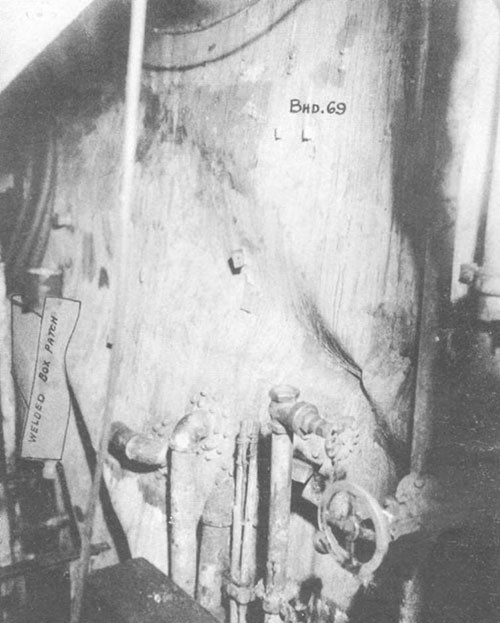
--38--
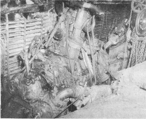
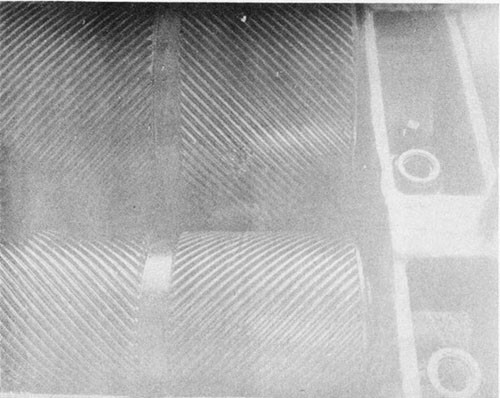
--39--
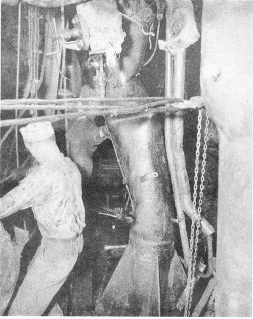
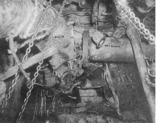
--40--
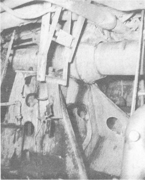
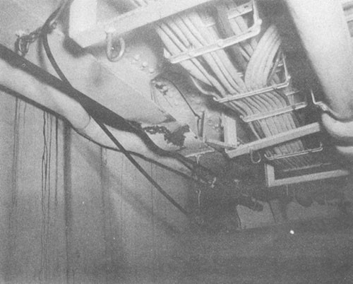
--41--
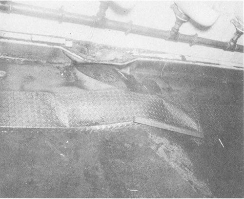
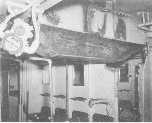
--42--
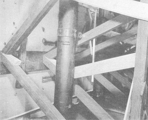
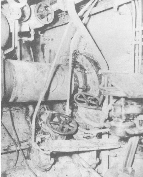
--43--
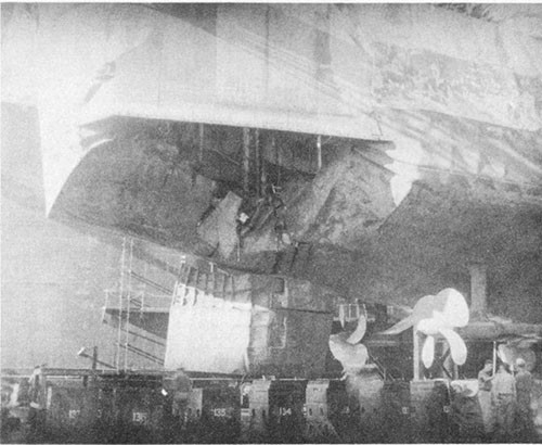
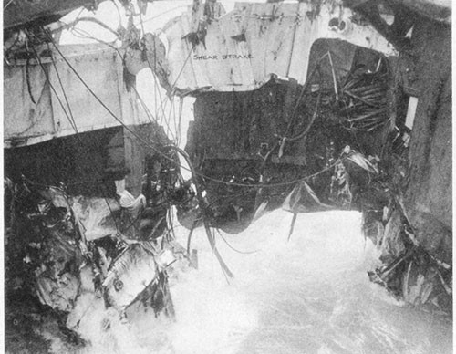
--44--
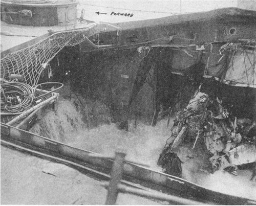
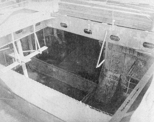
--45--
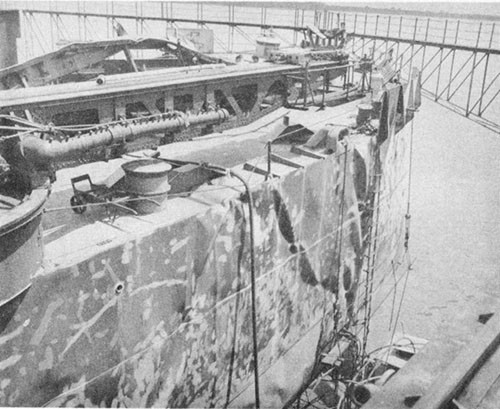
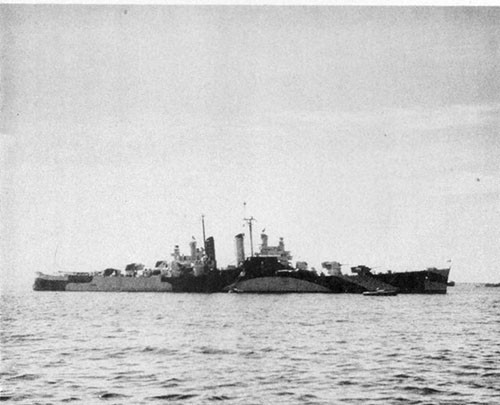
--46--
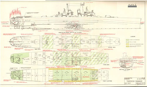
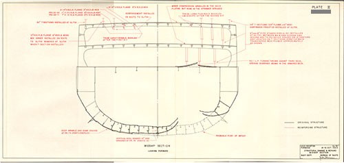
[END]


