The Navy Department Library
Structural Repairs in Forward Areas During World War II
Restricted
STRUCTURAL REPAIRS
IN
FORWARD AREAS
DURING
WORLD WAR II
Bureau of Ships
Navy Department
December 1949
STRUCTURAL REPAIRS
IN
FORWARD AREAS
DURING
WORLD WAR II
APPROVED
/s/
F. E. HAEBERLE
Rear Admiral, USN
Ass't. Chief of Bureau for Ships
December 1949
CONTENTS
| NAME | CAUSE OF DAMAGE | PAGE |
| INTRODUCTION | ||
| ERIE (PG50) | Submarine Torpedo | |
| RENO (CL96) | Submarine Torpedo | |
| HOUSTON (CL81) | Submarine Torpedo | |
| CANBERRA (CA70) | Aircraft Torpedo | |
| O'BRIEN (DD725) | Submarine Torpedo | |
| WADLEIGH (DD689) | Mine | |
| NEWCOMB (DD586) | 4 Kamikaze Planes (1 Bomb) | |
| KEARNY (DD432) | Submarine Torpedo | |
| SELFRIDGE (DD357) | Submarine Torpedo | |
| FOOTE (DD511) | Submarine Torpedo | |
| INTREPID (CV11) | Aircraft Torpedo | |
| VIBURNUM (AN57) | Mine |
The problem of effecting temporary repairs to damaged ships was encountered frequently during World War II and was handled with varying degrees of success. It was never feasible to make complete repairs to seriously damaged vessels in the forward area. Accordingly, repair work ordinarily was limited to that which would enable the ship to proceed to a larger repair activity and eventually to a shipyard. Repairs to machinery and electrical equipment were in most instances limited to rerouting piping, installation of spare parts, preservation and baking out of intact equipment that had been in flooded spaces, or repairs normally considered within the capacity of the ship's force. These types of repairs are treated thoroughly in manufacturers instruction books, the Bureau of Ships Manual, training instruction books and other readily available sources. Comparatively little data is available, however, concerning the more important repairs to seriously damaged structure which are required to enable a ship to withstand the hazards of a voyage in the open ocean.
Examples of repairs made during World War II are presented to familiarize repair activities with types of problems with which they may be confronted and to facilitate their solutions of them. The selection of examples has been influenced by the desire to include representative types of damage, the availability of information concerning the repairs made and the effectiveness of the repairs. In most instances, the action of the repair activity was soundly conceived and executed. The cases of O'BRIEN and ERIE are included in contrast to emphasize the serious consequences of inadequate repairs or poorly conceived procedures. For the sake of brevity, details of procedures for unwatering flooded spaces, making attachments between original and replacement structures, removing damaged structure and the results of stability and strength calculations are presented only for selected examples. However, these phases are of paramount importance in all cases of damage repairs.
Ideally, repairs should restore the ship to her condition before damage. Usually, sufficient plans are available aboard a ship to indicate the scantlings of essential structure. In the event no plans are available, it is possible to obtain measurements from adjacent structure. However, limitations of time, manpower, materials and facilities usually will necessitate some compromise with the ideal. Nevertheless, it is imperative that the repairs, even though temporary, embody sound engineering principles and practices, be adequate to permit safe passage of the ship and be accomplished safely and without hazard to the ship or personnel.
--1--
Design Data for plating and stiffeners is contained in the Bureau of Ships pamphlets listed below which are included in the technical files of every repair activity. The standards prescribed in them represent sound practice and should be followed insofar as possible when repairing damaged structure.
(a) Design Data for T Section Beams and Stiffeners. C&R No. 002213-A.
(b) Design Data for Tee Type Beam and Stiffener Brackets. BuShips No. 015025.
(c) Formulae for Determination of Scantlings for Flat Plating and Stiffeners subject to Water Pressure. C&R No. 002213.
(d) Design Data for Tee Stiffeners. Proportions for Lateral Stability and Requirements for Lateral Support to Prevent Tripping. BuShips No. 017969.
The principal features illustrated by the included cases are:
1. Stability During Repairs.
This problem is discussed in considerable detail in Chapter 88 of the Bureau of Ships Manual. Before repairs are begun on any ship that has appreciable flooding, a careful estimate of stability should be made. A continuing analysis should be made of the effect on stability of moving, removing, or adding stores, equipment, floodwater, ammunition, structure, etc. ERIE provides a most serious example of the result of failure to make these calculations. The care taken to maintain continuous knowledge of the stability condition of RENO throughout her repairs provides a welcome contrast.
2. Restoration of Longitudinal Strength.
Ordinarily, there will not be sufficient data on hand in the forward area to permit a complete strength calculation. However, it is comparatively easy to calculate the moment of inertia of a section incorporating planned repairs and compare it with that of the intact section. Such a calculation will establish the adequacy of planned repairs. Failure to provide sufficient replacement structure to restore the loss of strength resulting from damage and to provide adequate continuity of the replacement structure was responsible for loss of O'BRIEN which was not severely
--2--
damaged by the initial explosion. The wide dissemination given this case aided in preventing similar occurrences during World War II. The cases of RENO, CANBERRA, HOUSTON, WADLEIGH and NEWCOMB illustrate more effective repairs to longitudinal strength.
3. Replacement of Local Strength.
Repairs to restore local strength and support for large weights are provided in the cases of RENO and SELFRIDGE. The goal of this type of repair is to insure continuity of support for massive items down to the shell.
4. Watertight Integrity.
Repairs to restore lost watertight integrity are discussed in detail in Chapter 88 of the Bureau of Ships Manual. They figure in every case of primary damage to the underwater body and in many cases where the primary damage occurred above the waterline. This feature is illustrated particularly In the cases of NEWCOMB, CANBERRA, RENO and HOUSTON.
5. Temporary Bow Structure.
The case of SELFRIDGE Is used to illustrate this type of repair which was required on many ships of destroyer and cruiser types.
6. Temporary Stern Structure.
The case of FOOTE illustrates this type of repair to damage that was experienced in several instances by destroyers.
7. Temporary Steering Facilities.
The adverse effect of loss of deadwood aft was frequently observed in attempts to tow damaged ships. The fixed fins installed on FOOTE were very effective in reducing yaw during towing operations. In other cases of such damage to destroyers, temporary movable rudders that could be positioned by chain falls or by training of a gun mount proved equally effective. INTREPID was able to maneuver satisfactorily by use of her engines despite a damaged rudder that was positioned off-center. When the rudder was removed, however, the ship became unmaneuverable. A temporary rudder, positioned by cables that were run to the stern winch, restored her ability to maintain course within reasonable limits.
--3--
8. Use of External Cofferdam.
Underwater repairs to KEARNY were made In Iceland when no drydock facilities were available. A cofferdam that was positioned by hogging lines and secured to the ship's side by water pressure was used in this instance. Plans were made for repairing WADLEIGH by the same method. After the cofferdam was built, however, drydock facilities became available, so the cofferdam was not used.
9. Steel Repairs to Wood Vessel.
The completely satisfactory repairs to VIBURNUM exemplify the practicability of this type of repair.
--4--
USS ERIE (PG 50)
| Ship: | USS ERIE (PG 50) |
| Cause of Damage: | Submarine Torpedo |
| Date: | 12 November 1942 |
| Place: | Willemstad, Curacao, N.W.I. |
| Class: | PG 50 |
| Standard Displacement: | 2000 tons |
| Length Overall: | 328' 6" |
| Extreme Beam: | 41' 3" |
| Draft Before Damage: | 14' 2" |
| Launched: | 29 January 1936 |
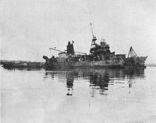
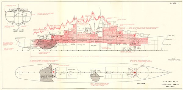
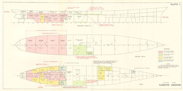
1. At 1733, 12 October 1942, a torpedo detonated about 5 feet below the waterline at frame 126, starboard (Plate 1, 2). The hull below the waterline was ruptured for a length of 45 feet. Transversely, the break extended from 5 feet to starboard of the keel up to the main deck and across the main deck almost to the port side (Photo 1). Fuel oil, diesel oil and gasoline tanks in way of the explosion were demolished, and the platform and second decks were ruptured. On the 2nd deck, bulkheads 119 and 131 were torn and the watertight door in bulkhead 107 was distorted and could not be closed. Oil and gasoline spread throughout the flooded 2nd deck compartments between bulkheads 99 and 141. This flooding represented about a 25% loss of waterplane area. A few seconds later a second explosion of considerable intensity occurred in the same area, probably the result of ignition of gasoline vapor. Fire, fed by gasoline and fuel oil, spread rapidly throughout the 2nd deck and through the after superstructure. Within 12 minutes, ready service ammunition for 6" mount 4 began to explode.
2. The torpedo detonation produced an initial list to port, but immediately thereafter ERIE began listing gradually to starboard and settling by the stern. Course across wind was maintained for a few minutes to prevent spread of the fire forward to the 6" ready service rooms and aft to the depth charge stowage. Increasing list and trim made sinking appear imminent, so course was changed to head for the beach about 4 miles away. List had increased to 15° and the main deck was underwater aft of frame 104 starboard when ERIE grounded at 1823. After grounding ERIE assumed a slight port list following the contour of the bottom.
3. After grounding, burning oil and gasoline spread forward and encircled ERIE, except for a small portion of the bow. Almost the entire superstructure was afire within 2 minutes. ERIE was abandoned at 1826, 3 minutes after
--5--
grounding. The uncontrolled fires had nearly burned out by 14 November when a party boarded ERIE and extinguished all fires above the 2nd deck. Fires below the 2nd deck were not extinguished until the following day. While ERIE was beached the port shaft alley flooded as the result of grounding damage.
4. Salvage operations under the direction of Merritt, Chapman and Scott were begun on 19 November. The topsides were stripped, debris was removed from the 2nd deck, store; were removed from the platform decks and several tanks were emptied. The anchors and chains were removed making the total weight removed about 375 tons. About 20 tons of oil remained in A-4F and A-418F. The stern aft of the damaged area remained buoyant during the entire time ERIE was beached.
5. On 28 November, ERIE was hauled off the beach and towed to Willemstad Harbor. When refloated, drafts were 8 1/2' forward and 24' aft and ERIE had a 8 1/2 port list. The stern drooped an estimated 24". Between 28 November and 5 December operations apparently were limited to removing accumulations of rainwater and seepage. At a conference on 3 December it was decided to place ERIE in a local drydock for sufficient temporary structural repairs to permit safe tow to a shipyard. It was decided to remove the list and reduce draft aft to 20' to prepare ERIE for drydocking. This was to be accomplished by removing additional scrap and debris, removing the fuel remaining in A-418F and A-4F, flooding forward compartments and placing counterweights on deck. On 4 December the anchors and chains were replaced and pumping of the two tanks was completed at 1930. This left ERIE with about a 5° port list.
6. At 0300, 5 December, 7 1/2 hours after pumping was completed, guards aboard observed that ERIE had righted and was beginning to list to starboard. Motion was slow and jerky and eventually stopped at about 10° when the hull rested against a fuel oil barge secured on the starboard side. D-1W, 43 tons capacity, which previously had been leaking at the rate of 200 gallons a day, was found to be full. Water was found to be running in on the 2nd deck from B-201-ILE, apparently through drains, and into C-201L. Flooding in C-201L extended at least to the centerline trunk since water was reported running down this hatch into the engine room. A slight gain was made on this flooding using a portable pump. A-418F and A-4F were completely filled to remove the list. About 12 minutes after this operation was completed, ERIE started to come upright, then passed the vertical and with increasing acceleration capsized to port.
--6--
Analysis of Stability, (Plates 2, 3)
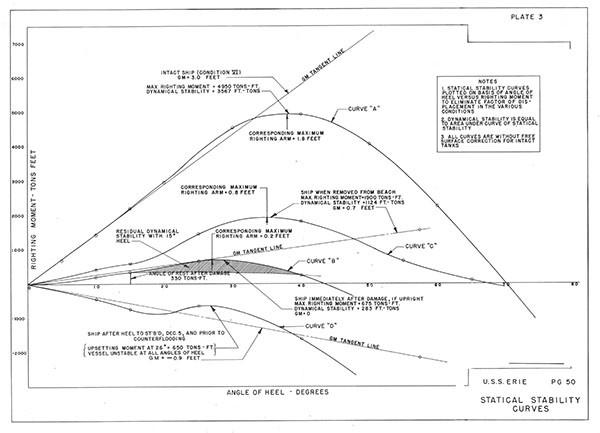
7. The best estimate of ERIE'S displacement before damage is 2730 tons, giving a corresponding draft of 14' 2". This corresponds closely with Condition VI of the inclining experiment data. Curve A of plate 3 is the curve of statical stability for this condition. GM, uncorrected for free surface, was about 3.0'. Although the distribution of liquids is uncertain, free surface correction could not have been greater than 3" and is omitted. ERIE was In a condition which offered the greatest resistance to underwater damage and also provided satisfactory stability characteristics.
8. As determined from the inclining experiment, the metacentric radius (BM) before damage was about 11.1'. Flooding resulting from the explosion reduced the waterplane area by about 25%. A quick estimate of GM after damage which could and should have been made on the spot is as follows: Assuming BM varies linearly with length of the Intact waterplane, a 25% reduction in the length of the intact waterplane is accompanied by a 2.8" reduction in BM and approximately the same loss of GM. This hasty estimate Indicates that before beaching GM was reduced to 0.2' a precarious condition of initial stability. More precise calculations made later indicated that GM, uncorrected for free surface in the forward tanks, actually was about zero. Curve B of plate 3 is the statical stability curve of ERIE immediately after damage. In this condition the maximum righting moment Is 675 tons-feet, 14% of that before damage. The range of stability decreased from 70° to 43°. The total dynamic stability required to cause capsizing was reduced from 3567 to 283 foot-tons, a reduction of 92%, Flooding of the starboard shaft alley, D-403E, which was the only known unsymmetrical flooding, produced a heeling moment of 330 tons-feet which Curve B indicates would produce a list of 15°, the list actually reported by ERIE. The crosshatched area on Curve B is the residual dynamic stability with 15° list and shows that the dynamic stability in the upright condition was reduced about 2/3 when the 15° list was assumed. These detailed calculations reiterate the critical stability condition of ERIE when beached.
9. About 375 tons of weight were removed during salvage operations while ERIE was aground. Although all possible topside weights were removed, much of the removed weight, including 200 tons of liquid, was low. Therefore, the lowering of the center of gravity and increase in GM was comparatively small for the amount of weight involved.
--7--
The center of gravity was lowered only 0.4' and GM was increased only to 0.7'. Curve C of Plate 3 is the stability curve for this condition. At small angles, below about 15°, the effect of weight removal Is not appreciable. The greatest effect was to increase the maximum righting moment to about 1900 tons-feet and to increase the range of stability nearly to the intact value. The total dynamic stability required for capsizing was increased to 1124 tons-feet, about 32% of the intact value. Although stability when ERIE was refloated was considerably better than it had been before beaching, ERIE was still in a critical condition. The 8 1/2° port list when ERIE was refloated could have been caused by unsymmetrical distribution of remaining weights. The flooding of the port shaft alley and the 20 tons remaining in A-4F and A-418F would have been sufficient to cause this list had ERIE been otherwise balanced.
10. The effects of the activities on 4 December, i.e., replacing the anchors and chain and removing 20 tons of liquid from A-4F and A-418F, was to reduce GM from 0.7' to 0.5', to reduce the port heeling moment by about 200 tons feet, thereby reducing the port list from 8 1/2° to 5°. Neither the removal of liquid nor adding of topside weight was advisable, even though initial stability remained positive after the operations. They indicate lack of appreciation of ERIE'S poor stability condition.
11. D-1W apparently flooded slowly, since the list did not change abruptly. This flooding produced a 667 tons-feet heeling moment, which from curve C would cause 18° total list. Since ERIE had a 5° port list, a 13° starboard list could be expected. Actually, the barge alongside prevented listing beyond 10°. Flooding of D-1W produced an after trimming moment of 5200 tons-feet which would cause a 34" change of trim, reasonably close to the 3' estimated by the Commanding Officer. Flooding of D-1W also caused a slight increase in GM.
12. The free surface effect, incident to the flooding on the 2nd deck, reduced GM by 1.6' to -0.9'. ERIE probably would have capsized to starboard had not the barge prevented. Counterflooding of A-4F and A-418F provided an ever increasing port moment. Curve D of Plate 3 is for D-1W flooded, free surface to the centerline of C-201L, and A-4F and A-418F empty. It is a close approximation of ERIE'S stability condition immediately before counterflooding and capsizing. Since neither initial nor dynamic stability was positive, the only immediate action which could have saved ERIE was rapid removal of free surface in C-201L and cautious addition
--8--
of low ballast either on or to starboard of centerline, thereby taking advantage of the support given by the barge in preventing capsizing to starboard. Although counterflooding A-4F and A-418F increased GM to -0.6', it produced a port heeling moment of 975 tons-feet and made capsizing to port inevitable. The negative stability curve explains the increasing acceleration of the roll to port.
13. From the available information, it appears that no formal estimates or calculations of ERIE'S stability were made at any time during the various phases of the operation. If her stability condition had been known, even approximately, it is probable that more active measures to improve stability would have been undertaken during the period 28 November to 4 December, that low liquids would not have been removed and high weights added on 4 December, and that A-4F and A-418F would not have been flooded so readily.
14. Preparing a vessel with low stability for drydocking is a complex problem and invariably requires a detailed stability analysis and carefully planned operations. It is impossible to establish a definite set of rules to be followed in such cases, since each case is a problem in itself. RALEIGH was successfully drydocked after damage at Pearl Harbor on 7 December 1941, even though GM was only a few inches, a port list existed, and the ship was trimmed 12' by the bow. A complete stability analysis was made and the program for correcting list and trim was worked out in chronological detail before operations began. All preparations for drydocking, including calculations, took about 2 weeks.
--9--
--10--
USS RENO (CL 96)
| Ship: | USS RENO (CL 96) |
| Cause of Damage: | Submarine Torpedo |
| Date: | 3 November 1944 |
| Place: | Off Luzon |
| Class: | ATLANTA (CL 51) |
| Standard Displacement: | 6000 tons |
| Length Overall: | 541' |
| Extreme Beam: | 53' |
| Draft Before Damage: | 20' 10 1/2" |
| Launched: | 23 December 1942 |
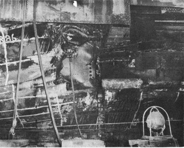
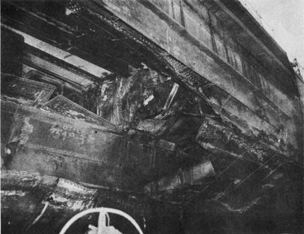
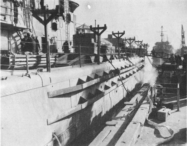
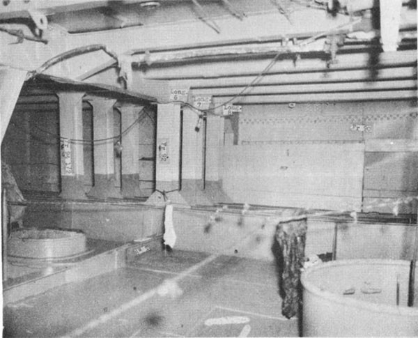
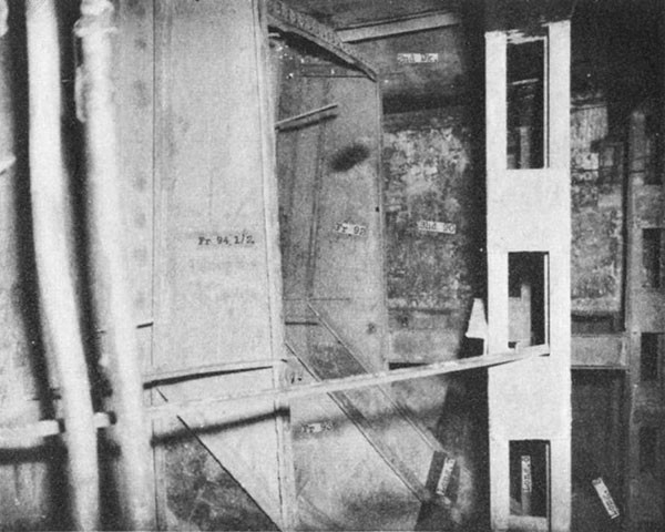
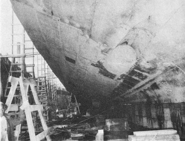
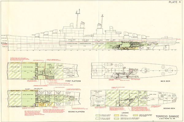
1. A submarine torpedo detonated at about frame 92, port, in way of shell strake "C", and caused serious local damage. Shell plating and supporting structure was ruptured between frames 88 and 97, a distance of about 33 feet, and from "B" strake to "F" strake, a distance of about 22 feet. Damage to adjacent plating extended between frames 84 and 103 and from "A" strake to the main deck. The main, 2nd and 1st platform decks were destroyed between frames 88 and 97, port. This damage as well as that to the main deck and interior structure is shown on Plate 4 and Photos 2 and 3. Extensive flooding resulted in a condition of negative initial stability, however, damage control measures undertaken by the ship's force and ZUNI (ATF 95) enabled the ship to be towed 700 miles to Ulithi. Despite the marked loss of strength at frame 93, port, no progressive structural failures were noted during this passage in heavy weather.
2. No drydocking facilities were available at Ulithi. Temporary repairs were undertaken by VESTAL (AR 4) and RENO with the aim of making the best possible improvement in stability, watertight integrity, and longitudinal, transverse and local strength. Immediately upon arrival and throughout repairs divers were used to determine the extent of damage, both In the vicinity of the explosion and to the rest of the underwater body and appurtenances.
a. Stability During Repairs (Refer to Plate 4).
On arrival, RENO had 1800 tons of flood water and GM had been reduced from 3.5' to 1.4'. B3 had been dewatered, but B4 was completely flooded. Flooding extended aft to bulkhead 110 on the 2nd platform, and frame 103 on the 1st platform. C-201L and C-202L were flooded to the waterline. Calculations of the stability condition showed that it would be necessary to remove 200 tons of topside weight before It would be safe to accept the free surface in the after engine room resulting from unwatering flooded spaces aft to bring the
--11--
2nd deck above the waterline. Accordingly, about 200 tons of the highest practicable topside weights were removed. A careful record of weight and moment of removed items was made for use in a continuous calculation of stability. Forward tanks A-1W, A-2W, A-4F, A-5F, A-7F, A-8F, A-608F and A-609F were ballasted solid with oil or water. Then, C-412M and C-415M were unwatered to bring the 2nd deck above the waterline. C-201L and C-202L were dewatered. Later, the ship was listed to starboard to facilitate repairs near the waterline.
b. Structural Repairs (Plates 5, 6, 7 and 8).
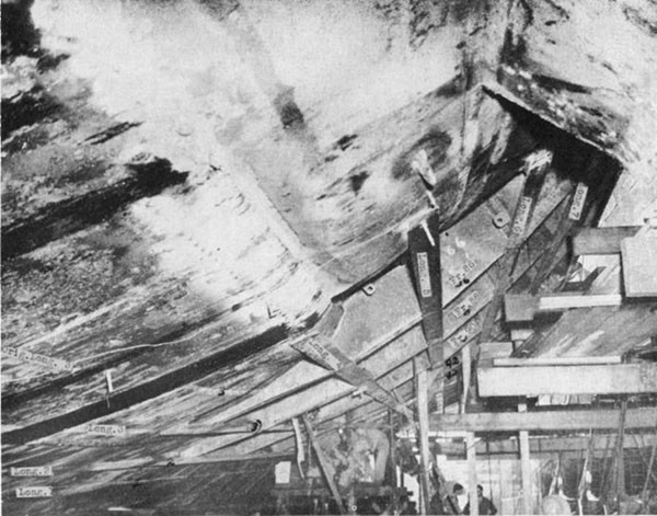
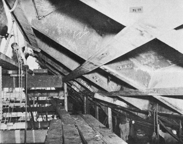
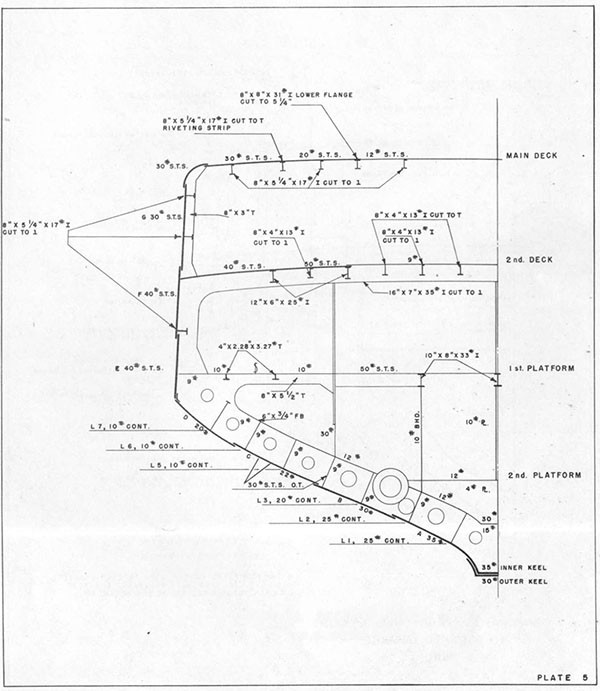
The section modulus of the damaged section was calculated using information obtained from examination of the underwater body by divers. This calculation indicated that it would be possible to restore about 75% of the strength of the intact section. As shown on Plate 6, damaged areas of the main and 2nd decks were replaced and two shell wrapper plates were installed below the port sheer strake. Additional large longitudinals were installed on the shell and main and 2nd decks (Photos 4, 5). These girders extended about 30' beyond each end of the damaged area. Their ends were tapered over a length of 8' and anti-tripping brackets were installed in way of each transverse structural member. In order to improve stiffness and transverse strength in way of the damage, a damaged section of bulkhead 96 was replaced and bulkheads 88 and 96 were strengthened by adding vertical bracketed 8" channel sections in way of existing stiffeners. Web frame 92 was replaced and 10" H columns were installed between the deep main and second deck longitudinals at each transverse web frame (Photo 5). 8" I stanchions were installed to replace damaged stanchions supporting turret 4. Holding bulkheads 77 in B-3 and 103 in C-412 and C-311AC were shored.
c. Watertight Integrity.
In addition to the improvement in watertight integrity resulting from the repairs to decks, shell, and bulkheads, damaged access closures, ventilation ducts, and piping were repaired or blanked.
--12--
3. After completion of these repairs, RENO was towed to Manus and drydocked in ABSD 2, where temporary repairs to the underwater body were made by WHITNEY (AD4), Navy Repair Unit 3205 and RENO. The care taken to align replacement members with original structure and to achieve continuity in way of all connections is shown in Plates 7, 8 and Photos 6, 7. Stanchions were installed at frames 90, 92 and 94 1/2 to compensate for the bulkhead which was not replaced at frame 90 and to provide additional stiffness (Photo 8).
--13--
--14--
--15--
--16--
--17--
--18--
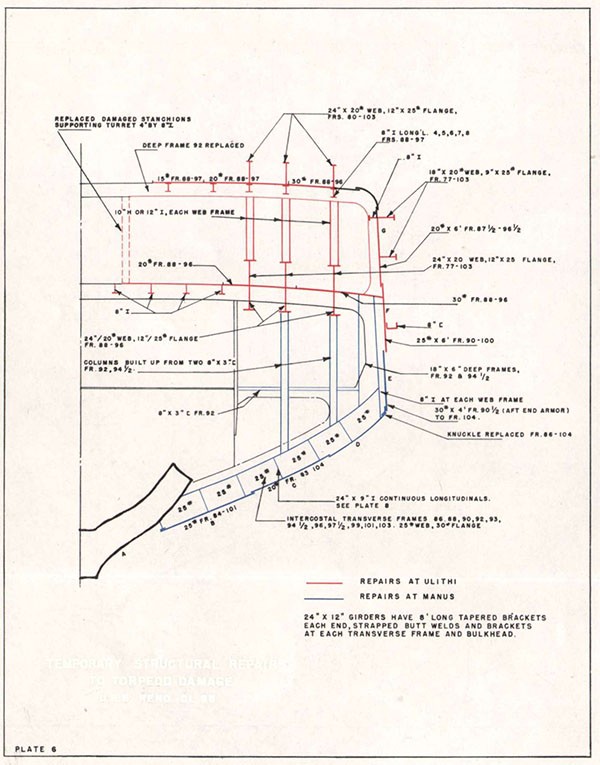
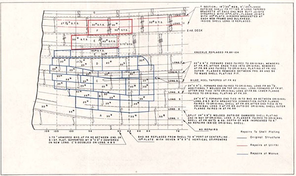
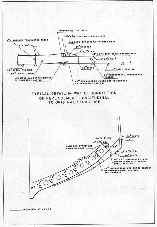
USS HOUSTON (CL 81)
| Ship: | USS HOUSTON (CL 81) |
| Damage: | 2 Torpedoes |
| Date: | 14 and 16 October 1944 |
| Place: | Off Formosa |
| Class: | CLEVELAND (CL 55) |
| Standard Displacement: | 10,000 tons |
| Length Overall: | 610' 0" |
| Extreme Beam: | 66' 4" |
| Draft Before Damage: | 24' 1-1/2" |
| Launched: | 19 June 1943 |
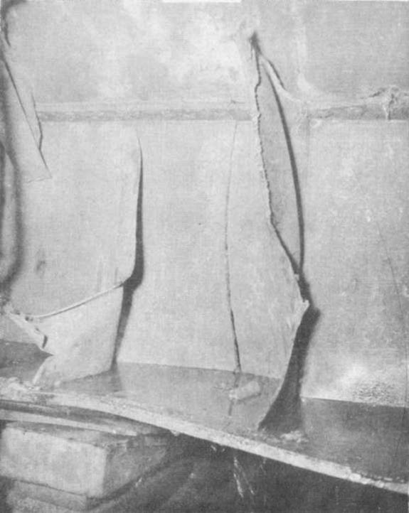
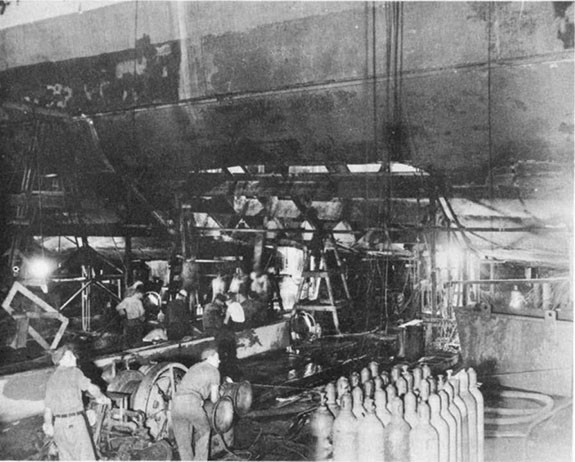
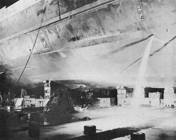
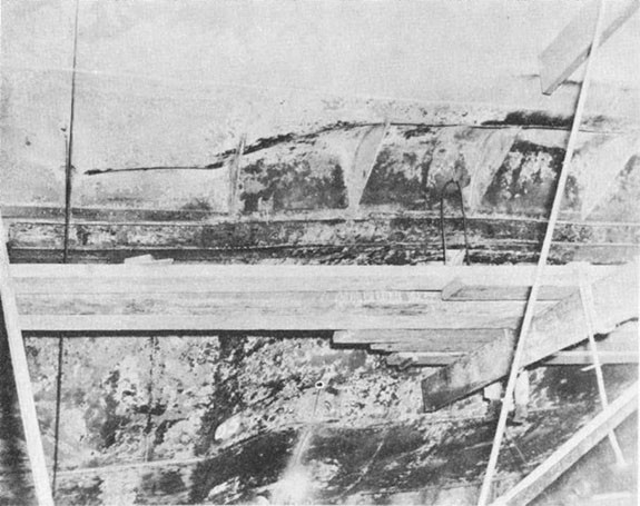
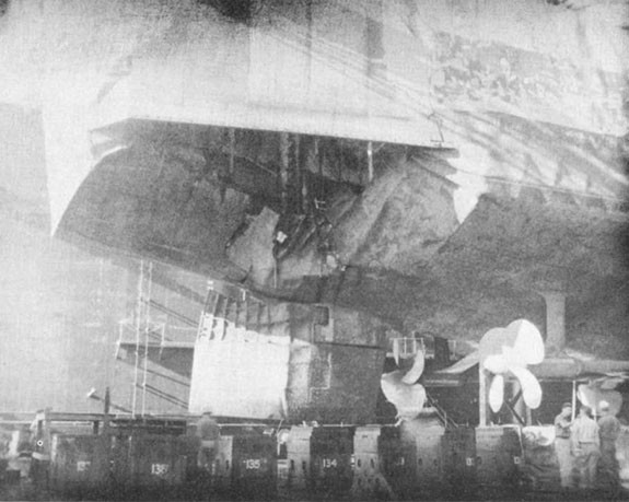
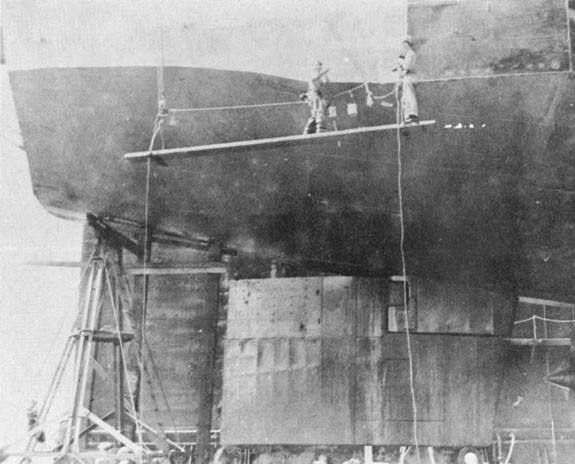
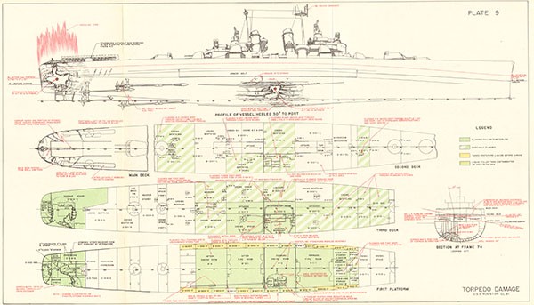
1. At 1841 on 14 October 1944, while HOUSTON was heeling to port during a high speed turn to starboard, an aircraft torpedo detonated in contact with the bottom at frame 75, midway between the centerline keel and the starboard bilge keel. The forward engine room, B-2, flooded immediately through a 10" diameter hole in the shell plating. Bottom structure was seriously damaged over an area 32' long by 24' athwartships (Photo 10, Plate 9). The keel was hogged 14" and cracked at frame 74 (Photo 11) Wrinkles extended around the girth to the bottom of the port side armor belt at frame 74. As HOUSTON was wracked by the seas, compression wrinkles developed amidships in the port main deck stringer plate and in some port main deck longitudinals. The forward fireroom, B-1-1, flooded in 10 minutes through a wrinkled and torn section of bulkhead 69, about 24 feet from the explosion. Boilers in this space were secured from valves on the third deck. The after fireroom, B-3-1, flooded very quickly through tears in the badly crumpled area at the bottom of bulkhead 79. Despite serious local damage, bulkhead 79 supported the bottom structure and limited distortion of the shell aft of that point (Photo 10). Propeller shaft #1 was broken, and drag on the propeller pulled the shaft 5 1/2' aft. This damaged the shaft glands in the stern tube and bulkhead 91, permitting the after engine room, B-4, to flood in about 30 minutes. No. 1 LP turbine was thrust upward against the overhead of B-2 and opened two scarfed joints in the 2" STS armored 3rd deck in the machine shop, B-307L. Spaces on the third deck flooded through these openings and damaged access trunks. The extensive flooding on the 2nd and 3rd decks is shown on Plate 9. HOUSTON underwent a period of negative initial stability while B-1-1 and B-4 were flooding. The vessel finally stabilized at a displacement of 20,900 tons with 6400 tons floodwater aboard, GM of +0.2", a 16° starboard list, and the main deck awash when the ship rolled.
2. HOUSTON undertook, effectively, measures to establish flooding boundaries, unwater partially flooded compartments, reduce seepage, jettison topside weights and shore weakened
--19--
structure. By 1200 16 October, displacement had been reduced to 19,200 tons. The list had been reduced to 8° starboard, GM had increased to 4.5', and the main deck edge no longer dipped under as the ship rolled.
3. At 1348 on 16 October, a second aircraft torpedo detonated at frame 145, starboard. The resulting hole in the bottom and side plating extended from frame 138 aft and partially across the stern (Plate 9, Photo 12). Compression failures occurred in main deck plating and longitudinals aft of frame 129 and in port and starboard shell plating aft of frame 115. Flexural vibration caused further distortion of previously damaged longitudinals in the midship area under the main deck, port, and failure of some previously undamaged starboard main deck longitudinals. Main and 2nd deck plating was wrinkled to varying degrees throughout the ship. Flooding after the second hit increased displacement by 1100 tons to 20,300 tons, reduced the starboard list from 8° to 6°, and reduced GM to 4.0'.
4. The longitudinal strength of ship girder was weakened seriously by these two explosions. About 926 square inches of structural material, including the damaged main deck stringers and longitudinals, were destroyed or rendered ineffective in the midship section where greatest longitudinal bending moment occurs. This represented a 24% reduction in the area of the intact midship section. Since most of the damage was near the bottom of the ship girder, the neutral axis of the section moved upward 3.6'. Section moduli to the main deck and keel were reduced respectively to 75% and 53% of the intact condition.
5. HOUSTON continued damage control measures to:
(a) Confine flooding, eliminate free surface, lower the center of gravity of the ship, and reduce list. When the ship arrived at Ulithi on 27 October, the starboard list had decreased to 2° and mean draft had decreased 5".
(b) Reduce fire hazards.
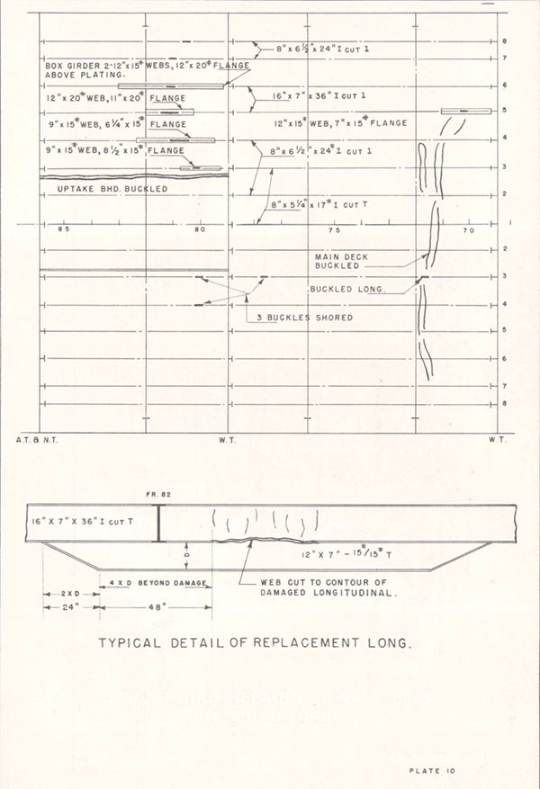
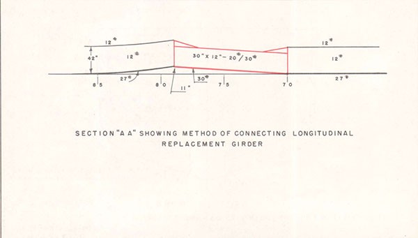
(c) Strengthen damaged structure. Bulkheads of the flooding boundary were shored. Stiffeners to reinforce some of the damaged main deck longitudinals were fabricated from 15# and 20# plate, carried for damage control purposes (Plates 10, 11, Photo 13). Webs of the replacement girders were cut to the contour of the damaged longitudinals.
--20--
All girders were of sufficient length and had tapered end connections to provide continuity of structure. These were the most extensive repairs to longitudinal strength taken during World War II by a ship's force underway. Analysis shows, however, that the repairs replaced only 38 square inches or 4% of the damaged area at frame 75. The neutral axis was raised 0.2'; the section modulus to main deck was increased by 3%, or to 78% of the intact condition; the section modulus to keel was increased 1% to 54% with a corresponding decrease in tensile stress In the keel.
6. At Ulithi there were no drydocking facilities capable of handling HOUSTON. Repair efforts were directed towards regaining buoyancy and restoring watertight integrity, increasing longitudinal and local strength, and rehabilitating machinery and electrical components. Divers were used to determine the extent of damage to the underwater body so that plans for repairs could proceed. When HOUSTON arrived at Ulithi the major spaces which still were flooded were the four engineering spaces, B-301E, B-306E, B-307L, B-311E, B-311L, and the 3rd deck and 1st platform spaces aft of bulkhead 136. Measures undertaken were:
(a) Regaining buoyancy and restoring watertight integrity.
(1) A 6" salvage pump was used to unwater B-313L after divers had entered the compartment and closed door 3-79-3 and 3-85-1. Although most of the oil had been skimmed from this space before pumping, a small amount remained. This remaining oil greatly increased the labor required to clean the compartment. The ship's force used greater care in removing oil from other compartments and were convinced that this procedure saved much time and labor.
(2) Divers examination indicated that a section of shell plating in way of No. 1 shaft stern tube was pulled away from the hull. Blankets and kapok life jackets stuffed into the stern tube through this opening sealed the leak sufficiently to permit pumping the after engine room. When the water level reached the upper level gratings,
--21--
bulkhead 91 was inspected for evidence of incipient failure and the exposed part of the bulkhead was shored. When this was completed, the space was completely unwatered and shores were installed over the entire bulkhead. All leaks around pipe lines and cables in bulkhead 91 were plugged. Welded steel boxes were installed to seal leaks around No. 1 shaft in bulkhead 91 and the stern tube.
(3) Holes in bulkhead 69 were patched temporarily from B-2 by divers. As water was pumped from the forward fire room, bulkhead 69 was inspected and shored from the forward side. Tears were then sealed with welded steel boxes.
(4) Removal of water from B-1-1 and B-4 reduced the draft so that only 3' of water remained in B-306E and B-307L. B-307L was entered from the 2nd deck through trunk B-309T and door 3-70. Timbers were laid around the displaced portion of the armored deck, shored in place, and calked. Deck drains in B-306E were plugged and the two compartments were unwatered. Welded steel brackets were installed to secure the timbers around the raised plating. Then the shores were removed, all leakage was calked, and a watertight steel box was welded around the edge of the damage area enclosing the break and the wood patch.
(5) A 10# transverse bulkhead 6' high was built across the deck of the hangar at frame 138-1/2. When this bulkhead had been tacked in place by underwater welding, the hangar forward of this bulkhead was pumped and welding of the bulkhead was completed. Two 4' high bulkheads were installed to subdivide the forward part of the hangar (Photo 14). This restored buoyancy and reduced free surface in the stern area, reduced the likelihood of flooding C-416A and C-417A, and provided access to C-419A, C-421A, C-11V, C-12V and C-14V.
(6) C-419A and C-421A were filled with decomposed provisions. Divers entered through hatches 3-139-2 and 3-145. The provisions were floated up through the hatches and out through the torpedo hole at frame 145. Wooden cofferdams were built around hatches 3-139-2 and 3-145. The access opening at frame 139 in the starboard longitudinal bulkhead was sealed to permit
--22--
pumping the port and center sections of C-419A. The access opening in the starboard longitudinal bulkhead at frame 146 was sealed to permit unwatering the port section of C-421A. When this was completed a new hatch leading to C-419A was installed in the unwatered section of the hangar. A hose connection was installed In bulkhead 144 to provide drainage facilities for the unwatered portion of C-421A. Hatches 3-139-2 and 3-145 were then blanked and the cofferdams removed.
(7) In addition, liquid weights were temporarily removed from tanks in the midship area and the ship was listed to port to facilitate repairs to the 3rd deck.
(b) Improving longitudinal and local strength.
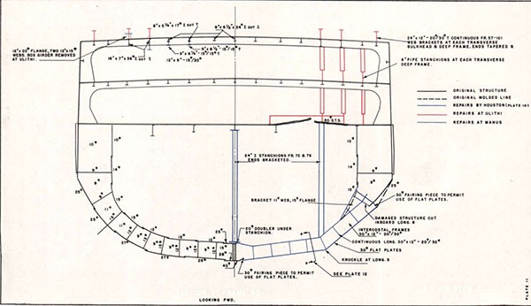
(1) HECTOR (AR7), assisted by HOUSTON, undertook structural repairs to compensate insofar as possible for the loss In longitudinal strength. 24" T longitudinals were installed on the main, 2nd, and 3rd decks as shown on Plate 11. The 2nd and 3rd deck longitudinals, in conjunction with the stanchions, were intended to form a deep box girder bridging the damaged area to increase the rigidity of the hull and insure that the available strength members would develop their maximum strength. The 2nd and 3rd deck longitudinals, being near the neutral axis, were much less effective than were those on the main deck in Increasing the moment of inertia of the section; in this instance a 2nd deck longitudinal was 44% and a 3rd deck longitudinal was 10% as effective as one on the main deck. These repairs added 252 square inches of material to the section and raised the neutral axis 11'. The section moduli to the main deck and keel were restored to 91% and 58% of their respective intact values.
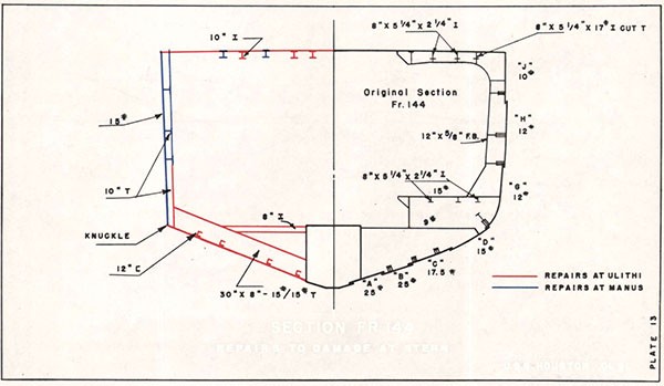
(2) In way of the after hit, badly damaged shell plating was cut away and temporary side plating, reinforced by longitudinal and transverse girders, was installed to tie together the remaining structure and to provide a partial breakwater against following seas (Photos 15,16).
--23--
7. Calculations made for HOUSTON on a standard wave under the various conditions existing during this period show the reduction in tensile stress in the keel resulting from the measures undertaken to have been:
| Stress reduction effected by structural repairs en route Ulithi | 1% |
| Stress reduction effected by structural repairs at Ulithi | 4% |
| Stress reduction effected by dewatering at Ulithi | 16% |
8. After tow to Menus, HOUSTON was drydocked in ABSD 2 for temporary repairs to the underwater body. The COMSERON 10 local representative directed repairs which required 12,000 man days.
(a) Midship Area (Plates 11 and 12)
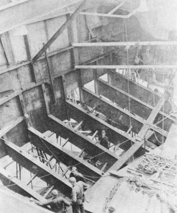
(1) Shell plating, longitudinals, transverse frames, and inner bottom were cut away between frames 70 and 79 and from the keel to #8 longitudinal (Photos 17 and 18). At frame 79, the shell plating was about 11" inboard of the molded line. Longitudinals 1 to 5 and the associated inner bottom were cut away back to frame 81 and then restored to their original strength. Welded straps were fitted on both sides of the crack in the vertical keel at frame 74 1/2. 30" x 12" - 20#/30# welded T replacement longitudinals were installed between frames 70 and 79 (Photo 19). Deep transverse frames were replaced by intercostal 30" x 12" - 20#/30# welded T's. 30# shell plating was installed in two flat sections with a knuckle at longitudinal 5 (Photo 20).
(2) Damaged centerline stanchions at frame 72 and 76 were replaced by 24" I sections with bracketed ends. Two additional 24" I stanchions were installed over the deep wrinkles in the shell plating frames 79-85, starboard (Photo 21). The cracked area in E strake at frame 75, starboard, was cut out and replaced by a 30# doubler. Smaller cracks were drilled at both ends, then welded and covered with a doubler.
--24--
(3) Plating and stiffeners in damaged portions of bulkheads 69 and 79 were replaced to restore original strength and watertightness.
(b) Repairs to After Torpedo Damage.
(1) Damaged structure was cut away. 36" x 8" -15#/15# T section transverse frames were Installed at 4' spacing to conform to the original design. 12" T intercostal longitudinals were fitted. 15# flat plating was installed, with a knuckle at the connection of the bottom plating to the side plating. At the 1st platform level, transverse 8" I's were installed at each frame (Plate 13, Photo 22). At frame 145 a cracked portion of the keel was replaced. At frame 128 a crack in the keel was welded and strapped.
(c) Repairs to Rudder
(1) Drydock inspection showed that the after portion of the rudder was 20° out of line with the forward portion and that the top was badly distorted. Therefore, the rudder was cut just aft of the stock; the top portion was replaced, and the after portion was reinstalled in proper alignment (Photos 23 and 24).
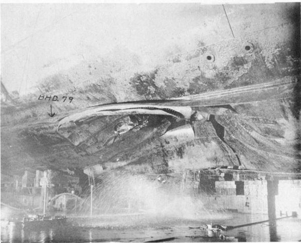
--25--
--26--
--27--
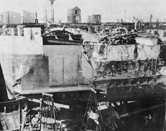
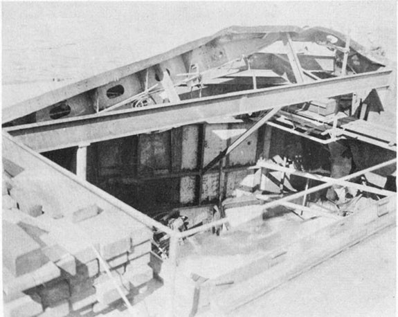
--28--
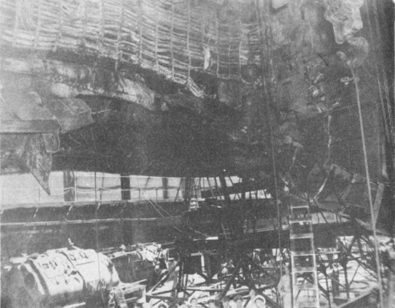
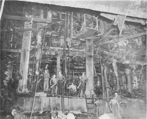
--29--
--30--
--31--
--32--
USS CANBERRA (CA 70)
| Ship: | USS CANBERRA (CA 70) |
| Damage: | 1 Aircraft Torpedo |
| Date: | 13 October 1944 |
| Place: | Formosa |
| Class: | BALTIMORE (CA 68) |
| Standard Displacement: | 13,600 tons |
| Length Overall: | 673' 5" |
| Extreme Beam: | 70' 10" |
| Draft Before Damage: | 24' 2" |
| Launched: | 19 April 1943 |
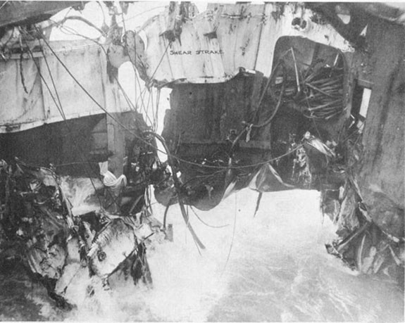
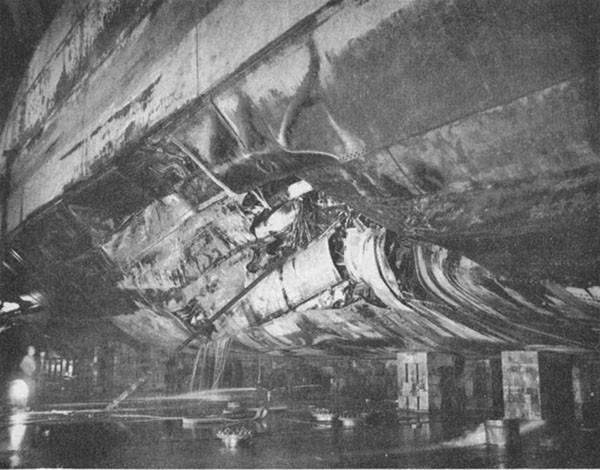
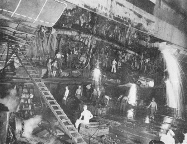
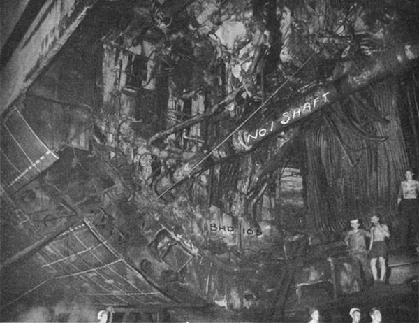
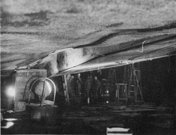
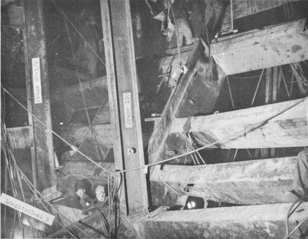
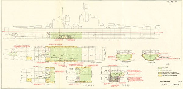
1. While participating in carrier strikes against targets in Formosa, CANBERRA was damaged by an aircraft torpedo that exploded at frame 99, starboard, about 18 feet below the waterline. Damage to the hull was of the same order of magnitude as that observed in other U. S. cruisers damaged by torpedoes. The side and bottom plating was ruptured from frame 95 to frame 104, starboard, and from 15 feet outboard of the keel up to the armor belt. Firerooms 3 and 4 flooded instantly. The starboard half of bulkhead 97 1/2 was blown forward with the lower portion pushed upward against the first platform in fireroom 3. No. 1 shaft was bent upward and inward in a long radius curve and tore large holes in bulkheads 90 and 105, which were not otherwise damaged by blast or fragments. This resulted in rapid flooding of engine rooms 1 and 2 (Plate 14, Photos 25 and 26). All propulsive power was lost. CANBERRA was taken under tow and on 27 October arrived at Ulithi, a distance of 1400 miles.
2. During the period 17 to 28 October, 138 hours of diving operations were conducted to determine the extent of damage to the forward engine room, to isolate piping systems, and to restore the watertightness of bulkhead 90, the after bulkhead of the space. Divers established that the principal source of flooding was through a 36-inch diameter hole in way of No. 1 shaft. The damaged shaft bulkhead gland was removed, as were the shaft revolution counter gear box and its foundation, the sheet metal guard for a shaft coupling, and electric cables in the vicinity of the hole. Then an electric underwater cutting torch was used to trim the jagged edges of the hole in the bulkhead. When this preparatory work had been completed, a patch was fitted around the shaft and covering the hole. This patch was made in two sections from 15 pound plate. It was bolted through the bulkhead and seated on a 1/4 inch rubber gasket. After this patch had been Installed, 15 hours of pumping were required to bring the water level down to mid-height In the compartment, a depth of about 12 feet. The upper half of the bulkhead was then shored. After this shoring was completed, pumping was resumed.
--33--
As the water level receded, additional shoring was installed and small leaks were plugged as they became apparent. Upon completion of these and other minor repairs, CANBERRA was towed to Manus, where drydocking facilities were available, for additional repairs; Arriving there on 17 November.
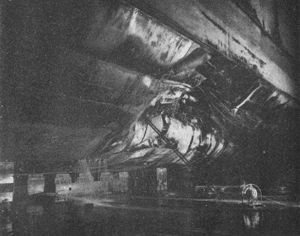
3. At Manus, CANBERRA was drydocked in ABSD 2 for unwatering of the remaining flooded spaces and temporary repairs to the underwater body. Inspection indicated that the keel was deflected inward between frames 94 and 105; the maximum being 2 3/4 inches at frame 99. Longitudinals 1 and 2 were hogged and slightly wrinkled between frames 90 and 105. Longitudinal 3 was partially fractured at frame 99 and bent between frames 90 and 105. Longitudinals 4, 4 1/2, 5, 6, 7, 8 and 9 were ruptured and bent between frames 90 and 105. Longitudinal 10 was partially ruptured and bent between frames 95 and 102. All transverse frames in way of the damaged longitudinals were distorted and required replacing. Shell plating was ruptured and bent in the damaged area.
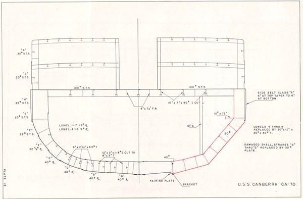
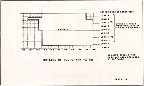
4. Hull repairs were planned to restore the original strength in the simplest manner (Plates 15 and 16). Flat plates were used whenever possible with a knuckle installed at longitudinal 6. Plates at the forward and after ends of the patch were shaped to make a fair transition between the flat plates and the original shell.
5. After removal of the damaged hull structure (Photos 27 and 28) and machinery, replacement longitudinals were installed.
(b) Longitudinals 4 through 9 were replaced by 30"/12" x 20#/30# T sections having the same depth as the original inner bottom.
(c) Longitudinal 10 was replaced by a 72" wide section of 15# plate, having a 10" faceplate and a panel stiffener of 4" angle iron.
6. Other repairs were:
(a) Intercostal web frames of 20# plate were installed to the depth of the longitudinals at frames 92,
--34--
95, 97 1/2, 100 and 103 (Photo 30). Intermediate frames were fabricated from 10" channels.
(b) 24" I stanchions were installed between longitudinal 6 and the third deck at frames 95, 97 1/2, and 100. At frame 97 1/2 additional stanchions and transverse beams made from 24" I sections were installed to replace the strength lost because of damage to bulkhead 97 1/2.
(c) The damaged portion of bulkhead 105 was repaired to restore the watertight integrity of the after engine room.
(d) A new main injection for the after engine room was installed.
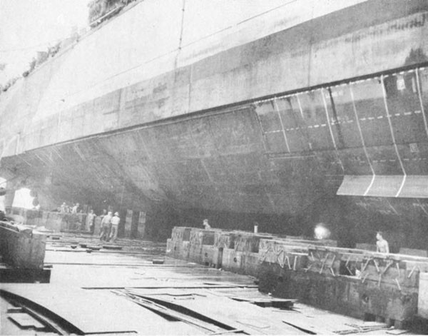
7. Exterior views of the completed repairs to the shell are shown in Photo 31.
--35--
--36--
--37--
--38--
USS O'BRIEN (DD415)
| Ship: | USS O'BRIEN (DD415) |
| Damage: | Submarine Torpedo |
| Date: | 15 September to 19 October 1942 |
| Place: | Solomon Islands |
| Class: | DD 409 |
| Standard Displacement: | 1570 tons |
| Length Overall: | 348' 3" |
| Extreme Beam: | 36' 0" |
| Draft Before Damage: | 11' 7" |
| Launched: | 20 October 1939 |
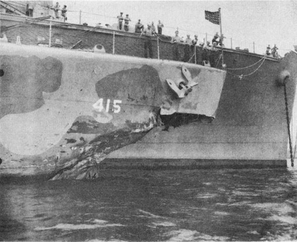
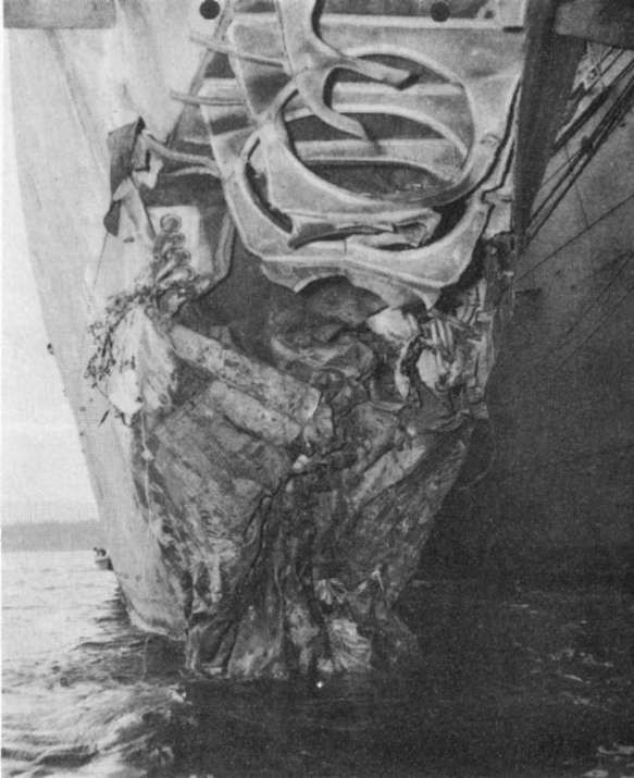
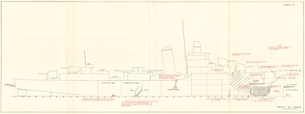
1. On 15 September 1942, a submarine torpedo detonated against the port side of O'BRIEN between the stem and frame 6 and about 10 feet below the waterline. The resulting local structural damage is shown in Photos 32 and 33 and Plate 17. The bow structure below the main deck and aft to frame 10 was blown away. Framing and plating were distorted back to frame 14. Free flooding occurred below the first platform between frames 10 and 22. As the bow plunged into sea, compartment A-202L on the first platform flooded slowly to a depth of 2 feet through ruptures in the first platform and bulkhead 14. Bulkhead 22 bulged aft but remained tight. Bulkhead 25 was not damaged. The draft forward, which was 11' 7" before damage, increased to 12' 2". This damage in itself was not serious and would not have placed the vessel in jeopardy.
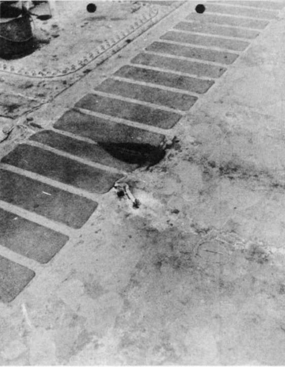
2. The explosion also caused severe flexural vibration of the hull girder. Photos 34 and 35 and Plate 17 show some of the moderate buckling of hull plating and longitudinals which resulted near frames 37, 78 and 123. The most serious failures were in the bottom structure between frames 104 and 108. Wrinkling and buckling of the shell and longitudinals extended from frame 104, starboard, across the bottom to frame 108, port. In this region the vertical keel, No. 2 and 6 deep longitudinals, several smaller longitudinals and shell plating all failed to some degree. Thus, the entire bottom flange of the ship girder was seriously damaged. In this area many rivets were loosened or sheared. There was considerable leakage through rivet holes and open seams into the forward engine room. Gun roller path data indicated that the after portion of the ship was twisted 1° to port.
3. While damage control measures were being undertaken, O'BRIEN proceeded under her own power at r.p.m. for 13 knots to Espirltu Santos, a distance of 280 miles. During passage, wind and sea were moderate with little or no swell, and maximum speed over the ground was estimated at 12 knots. O'BRIEN went alongside CURTISS (AV 4) at
--39--
Espiritu Santos on 16 September. The following repairs were made by O'BRIEN, CURTISS and the 7th Construction Battalion.
(a) Bulkhead 6 above the main deck, the deck of A-202L, and bulkhead 14 between the first platform and main deck were made tight by patching holes.
(b) Bulkheads 6 and 14 were reinforced with concrete.
(c) Bulkhead 14 and the deck of A-202L were shored.
(d) Divers installed bolts and patches to plug all holes in shell plating between frames 104 and 108. Forty hours diving time was required to accomplish this.
(e) Removed 150 rounds of 5" AA common and all except two 600# depth charges.
(f) Stowed anchors and chains aft.
4. O'BRIEN departed Espiritu Santos on 21 September and proceeded at a maximum speed of 11.5 knots to Noumea, a distance of 603 miles, arriving there on 23 September. During passage wind and sea did not exceed moderate intensity. During both passages O'BRIEN rode easily. Although regular inspections were made, no working of the two parts of the ship were observed. Repairs to the bottom, which were made in Espiritu Santos, reduced leakage into the forward engine room so that it could be controlled by one fire and bilge pump; whereas, the main circulating pump, operating at near capacity, had been required to control the leakage before arrival at Espiritu Santos.
5. At Noumea, ARGONNE (AG 31) made further temporary repairs:
(a) A partial bow section extending about half way to the waterline was installed to protect against the force of the seas during pitching.
(b) At frame 37, starboard, four vertical flat bar longitudinal stiffeners were installed on the forecastle deck and two partial longitudinals were installed to reinforce the sheer strake.
(c) At frame 77, starboard, three new longitudinal sections were installed to replace fractured girders under the sheer strake. In addition, a
--40--
tear In the sheer strake was welded and two partial longitudinals were Installed on both the port and starboard main deck stringers. Two partial longitudinals were installed on the starboard sheer strake.
(d) Details of repairs to the bottom structure, frames 103-109, in the forward engine room, are shown in Plate 18. Significant features of these repairs are:
(1) Deep sections were 21" x 10" x 3/8" welded T's, and extended over a length of 3 frame spaces (63"). Shallow sections were 4" x 3" x 12 1/2# welded T's and covered 2 to 3 frames. These scantlings were about the same or larger than those of the longitudinal which the temporary member was to reinforce.
(2) The reinforcing longitudinals were offset transversely from the damaged longitudinals they were meant to replace. The length of the new longitudinals was less than the distance between transverse web frames.
(3) No replacement was made for the loss of effective area of the hull girder resulting from damaged bottom plating.
(e) Five torpedoes, eight 300 lb. depth charges, 12,000 rounds of 20 mm ammunition, some SC radar equipment, and computer and 36" searchlight remote control spares were removed.
6. Upon completion of repairs at Noumea, O'BRIEN was considered capable of making 15 knots in a moderate sea. On 10 October, O'BRIEN in company with CIMMARON (AO 22) and LANG (DD 399) departed for Mare Island. After getting underway, a slight increase In the rate of leakage into the forward engine room was observed. This was not considered abnormal because of the many patches and loose rivets in the bottom. As a precautionary measure, the ship's force attempted to compare the bending across the damaged section with that across an undamaged section of similar length in the after engine room. The observed deflections were nearly identical. In view of the difficulty of obtaining reliable hull deflection readings at sea, these efforts probably were of no value. Shortly before arrival at Suva, a distance of 862 miles, on the morning of 13 October, the reinforcing plate installed on
--41--
No. 6 port longitudinal was found to have failed in tension. During this passage wind and sea did not exceed moderate intensity, and turns for 13 knots resulted in a ground speed of 12 knots.
7. At Suva, an angle was welded to the broken reinforcing plate. The damage and repairs throughout the ship were inspected thoroughly. No other indications of increased damage or weakening of the repairs were observed. At 1430, 16 October, O'BRIEN joined CIMARRON and LANG In the outer harbor. When the ship reached the open sea, leakage into the forward engine room again increased to about the rate previously experienced under similar sea conditions. One fire and bilge pump, operating slowly, controlled the leakage.
8. After leaving Suva, O'BRIEN crossed the international date line and 16 October was repeated. By early morning of 18 October, the rate of leakage had increased to the extent that one fire and bilge pump was required to control It. At 0500, 18 October, a second fire and bilge pump was started so that each might run at low speed. Inspection revealed that the reinforcement of No. 6 port longitudinal again had cracked in the same place as before. Just outboard of this longitudinal the shell plating had a 3 inch crack along a wrinkle. The rate of leakage continued to increase so that at 0900 the two fire and bilge pumps were secured and the main circulating pump was started. About 1000, the vertical keel was found to be completely broken and cracks were developing in the other deep longitudinals and in the shell plating. Course was changed to Pago Pago and to pass Upolo close aboard.
9. The ship's force undertook various precautionary measures to meet emergency conditions, including jettisoning topside weights, assembling the crew for instruction, arranging communication signals, reducing free surface in fuel tanks, etc. Throughout the remainder of the day and night, the rate of leakage into the forward engine room continued to increase, but still could be controlled by the available pumping facilities. At 0337, a shell plate on the port side behind the dynamo condenser broke with a loud noise and the water level rose slowly even after full pumping facilities were used. At 0430 it was necessary to abandon the forward engine room. At 0600 the bottom suddenly opened considerably and the forward and after portions of the hull began to work independently. At 0605 the starboard side cracked open up to the main deck. The ship was abandoned at 0630, and sank about 0800, having steamed 1027 miles from Suva and about 2800 miles after having been torpedoed.
--42--
10. Because complete details of the damage are not available, calculations of the structural condition of the ship have been made on the basis of the damage reported by the Commanding Officer. In calculating the condition of the ship after damage, it has been assumed that none of the damaged structure remained effective. Since some of the damaged structure undoubtedly remained partially effective, the actual section moduli probably are greater than indicated. In calculating the condition of the ship after repairs, it was assumed that all reinforcing members are fully effective. The variables involved in calculations of this type preclude accurate estimates, therefore, the results should be considered as changes which might have occurred rather than precise data as to what actually occurred. They serve to present the order of magnitude of the changes in strength of the ship girder.
| Before Damage | After Damage | After Repairs at Noumea | |
| Neutral Axis above Base | 10.25 ft. | 17.64 ft. | 13.78 ft. |
| Section Modulus of Effective Structure above Neutral Axis | 100% | 38% | 85% |
| Section Modulus of Effective Structure below Neutral Axis | 100% | 7% | 42% |
| Stress in Bottom Plating after Repairs, but before Flooding | - | - | 18 tons/sq. in. |
| Stress in Bottom Plating after Repairs and after Flooding. | - | - | 21 tons/sq. in. |
11. Failure of the bottom structure was progressive up to 0600, 18 October. Stress concentrations undoubtedly occurred in the lower edges of the reinforcing girders and caused failure of some of them. Failure of the previously damaged structure followed. This progressive failure is evident in the repeated failure of No. 6 port longitudinal reinforcing section, the small crack in the port shell at 0500, 18 October, the crack in the keel at 1000, 18 October, and the constantly increasing rate of leakage into the engine room. Tensile stress in the remaining structure must have increased as the engine room flooded, and additional failures probably occurred
--43--
during this time. The hull split up to the main deck shortly after the engine room flooded to the waterline, putting the ship in an extreme sagging condition. The main deck, starboard, started to rupture but did not fail completely.
12. O'BRIEN was lost because the repairs to the ship girder did not restore adequate longitudinal strength. Deficiencies in the repairs are:
(a) The damaged material was not replaced adequately. 260 square inches of material was damaged in some degree and only 100 square inches was replaced. It appears that the area lost due to wrinkled bottom plating was completely neglected. Medium steel was used to replace damaged high tensile steel without compensation for the difference in strength of the two materials.
(b) The replacement longitudinals were not of sufficient size and length, and were not properly located to distribute the loads properly. Since the longitudinals were only 63" long and the distance between web frames was 108", the longitudinals obviously were not long enough to convey the loading to intact structure and the ends could not have been adequately connected. The replacement longitudinals were not in line with the existing structure. This eccentric arrangement resulted in stress concentrations at the ends of both the replacement and the original longitudinals. The omission of additional plating or flanges on the lower end of the replacement longitudinals also served to increase the stress in these members.
--44--
--45--
--46--

USS WADLEIGH (DD689)
| Ship: | USS WADLEIGH (DD689) |
| Cause of Damage: | Mine |
| Date: | 16 September 1944 |
| Place: | Kossol Passage, Palau Islands |
| Class: | DD 445 |
| Standard Displacement: | 2050 tons |
| Length Overall: | 376' 5" |
| Extreme Beam: | 39' 7" |
| Draft Before Damage: | 13' 6" |
| Launched: | 7 August 1943 |
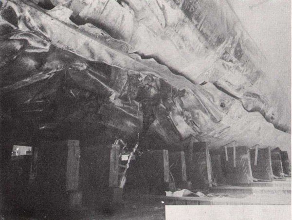
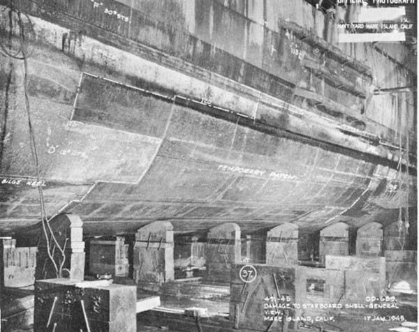
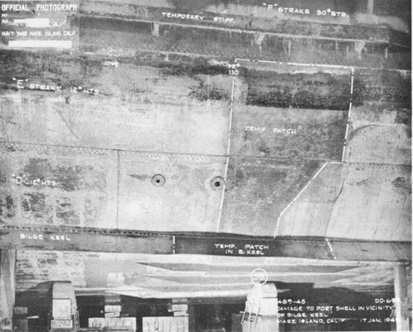
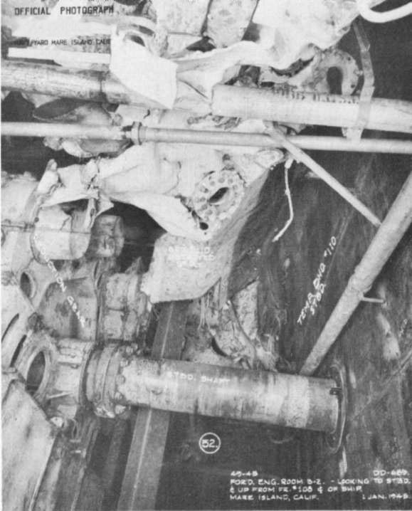
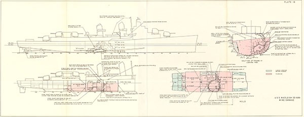
1. At 1428, 16 September 1944, while WADLEIGH was engaged in mine demolition operations, an unswept mine detonated at frame 112, midway between the centerline and starboard bilge keels. The ship was heaved upward in a critical hogging condition that caused a compression wrinkle around the bottom from deck edge to deck edge at frame 111. B-2 and B-3-1 flooded immediately through the hole in the shell, and B-4 flooded in about 2 minutes through a damaged area around the shaft gland in bulkhead 130 1/2. The flooding reduced reserve buoyancy by 1200 tons and produced a sagging condition that caused the damaged structure to fail in tension with a loud report. All power was lost. The hole in the bottom extended between frames 106 and 118 and between the centerline and longitudinal 7, starboard (Plates 19 and 21, Photo 36). The fracture in the shell plating extended between the lower edges of the port and starboard F strakes. At the fracture the thickness of a 1/2" plate was reduced to 5/16" and failure occurred in shear at 45°. F and G strakes, port and starboard, were kinked inward a maximum of 5" at the lower edge of F strake. The section modulus was reduced to about 14% of the intact value, and WADLEIGH undoubtedly would have broken in two had she not been in a protected lagoon.
2. WADLEIGH was towed to the nearby anchorage. The principal emergency damage control measures undertaken to restore buoyancy, improve stability, and reduce the sagging condition were:
(a) CLAMP (ARS 7) made emergency repairs to bulkhead 130 1/2 which permitted pumping B4.
(b) 95 tons of topside weight was removed, increasing GM 0.46'.
(c) 53 tons of fuel oil was transferred.
--47--
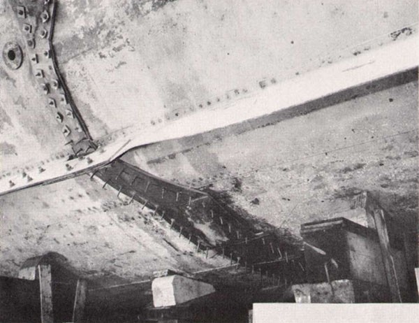
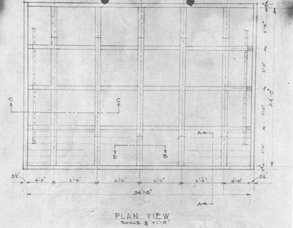
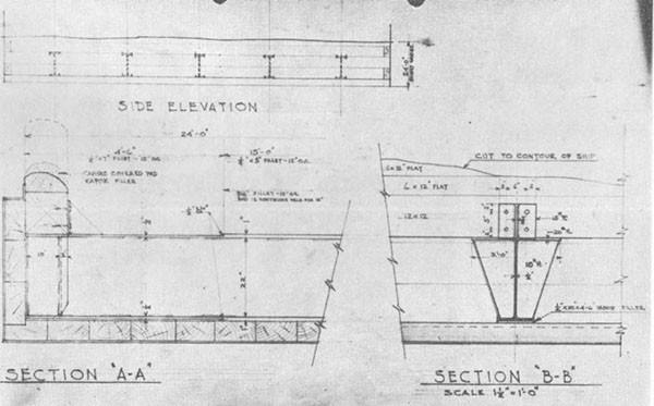
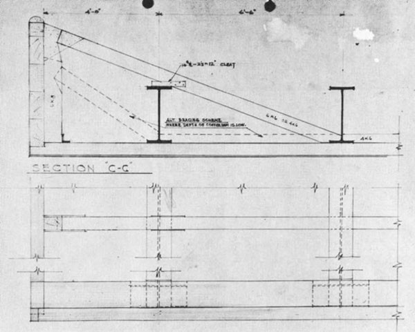
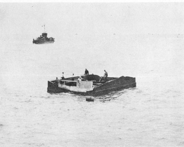
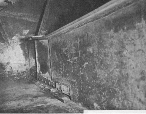
3. Repair work by PROMETHEUS (AR 3) began on 23 September. Since no drydock was then available and the loss of longitudinal strength made it unsafe to tow the ship, divers fitted patches on shell plating cracks (Photo 37) in preparation for pumping flooded compartments, using a temporary caisson over the main hole in the shell. Divers made templates of the shape of the hull where good support could be obtained beyond the extremities of the hole. The caisson, made of 6" planking with 24" x 10" x 100# x 24' long I girders and weighing 20 tons, was built to these templates (Photos 38, 39, 40, 41). When completed, it was payed with marine glue, a layer of canvas was ironed on, and a second layer of marine glue was payed on. The caisson then was ballasted to overcome its 4 tons positive buoyancy and eight 3/4" ropes and chain falls to the deck were used to rig it in place. Eighteen days were required for Its construction, two days for rigging and one day for caulking. When these operations had been finished, 5 feet of water were pumped. Later, the differential was reduced to 2 feet to prevent exposing the machinery to air. The caisson remained in place until WADLEIGH was drydocked in ARD 16 on 9 November 1944.
4. Repairs in drydock began with removal of damaged structure in the largest sections that could be handled. Plating and longitudinals were cut away to places where there was relatively little deformation so that effective replacement structure could be fitted easily. Plating butts were staggered insofar as possible and the longitudinals were cut back at least one frame beyond the plating (Photo 42). Oxy-Acetylene cutting torches were used to cut steel members; the electric arc method using coated medium steel electrodes was used to cut non-ferrous metals. About half of boiler 3 and all auxiliary machinery in way of the damage was removed. Salvageable components were secured in the fireroom at the completion of repairs. While damaged structure was being cut away, great care was exercised to insure that weights in the ship were properly supported by shoring. Shoring also was placed under the stern overhang to prevent excessive pressure on the skeg as the area of the midship section was reduced.
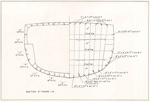
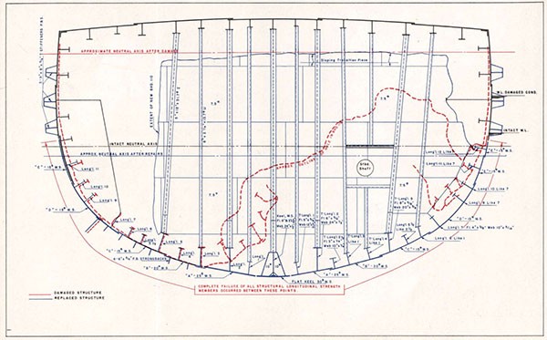
5. Only mild steel was available for replacing the high-tensile steel structure on WADLEIGH. Therefore, the area of the restored cross section was increased by using larger sizes for both plating and supporting structure. Between the bilge keels the area replaced was 365 square inches, a 26% increase over the original area of 288 square inches (Plates 20, 21, Table 1).
--48--
| Plate Keel - | 18 x 5/8 | 11.2 | 18 x 3/4 | 13.5 |
| "A" Strake | 48 x 1/2 | 24.0 | 49 x 5/8 | 30.0 |
| "B" Strake | 48 x 1/2 | 24.0 | 48 x 1/2 | 24.0 |
| "C" Strake | 60 x 3/8 | 22.5 | 60 x 3/8 | 22.5 |
| "D" Strake | 24 x 5/16 | 7.5 | 24 x 3/8 | 9.0 |
| Port | ||||
| Plate Keel | 18 x 5/8 | 11.2 | 18 x 3/4 | 13.5 |
| "A" Strake | 48 x 1/2 | 24.0 | 60 x 5/8 | 37.5 |
| "B" Strake | 48 x 1/2 | 24.0 | 42 x 1/2 | 21.0 |
| "C" Strake | 60 x 3/8 | 22.5 | 60 x 3/8 | 22.5 |
| "D" Strake | 24 x 5/16 | 7.5 | 24 x 3/8 | 9.0 |
| 178.2 | 201.5 | |||
| Longitudinals: | ||||
| Long'l #1 | 2 x 4.36 | 8.72 | 2 x 5.63 | -11.26 |
| Long'l #2 | 2 x 13.01 | 26.02 | 2 x 15.75 | -31.50 |
| Long'l #3 | 2 x 1.72 | 3.44 | 2 x 3.25 | -6.50 |
| Long'l #4 | 2 x 4.98 | 9.96 | 2 x 5.63 | -11.26 |
| Long'l #5 | 2 x 11.77 | 23.54 | 2 x 12.50 | -25.00 |
| Long'l #5 1/2 | 2 x 1.72 | 3.44 | 2 x 3.25 | -6.50 |
| Long'l #6 | 2 x 4.98 | 9.96 | 2 x 5.63 | -11.26 |
| 93.80 | 114.54 | |||
| Keel | 17.27 | 22.50 | ||
| Strongbacks | ///// | 27.00 | ||
| 289.27 | 365.54 | |||
| Percentage increase: | (365.54/289.27) x 100 = |
|||
6. All fitting, erection and welding of the replacement structure were carefully planned and rigidly supervised to attain the best possible continuity between the new and original structure; the instructions in General Specifications, Appendix 5, Specifications for Welding, being followed throughout. The largest possible sections, consistent with available handling facilities, were prefabricated both to facilitate work and to reduce the distortion due to weld shrinkage. Instructions specifically outlined were:
(a) Plate edges could be prepared by flame cutting, using cutting machines whenever possible, provided all scale was carefully removed before welding.
(b) Edges of 15# or lighter plating would be prepared by chipping.
(c) Butts on longitudinal strength members were to be staggered insofar as possible.
(d) Butts in a particular longitudinal or plating strake were to be butt-welded with single or double vee joints as consistent with approved practice.
(e) Seams were to be lap-welded with double fillets of the same dimension as the thinner plate.
(f) Longitudinals were to be attached to plating by continuous double fillet welds having an efficiency of 75%.
(g) All tack welds were to be inspected for cracks before production welding started.
(h) Each weld pass was to be chipped and brushed free of slag before the next pass was made.
(i) Wherever cracks were found, the entire weld was to be chipped out and rewelded.
(j) All continuous welding was to follow the step back or block sequence.
(k) Large vee-welds, particularly the transverse welds, were to be bead welds, except where downhand welding could obtain the same results.
(l) Not over 1/8 inch reinforcement was to be used on vee-welds.
--50--
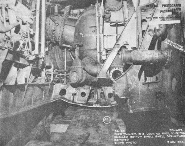
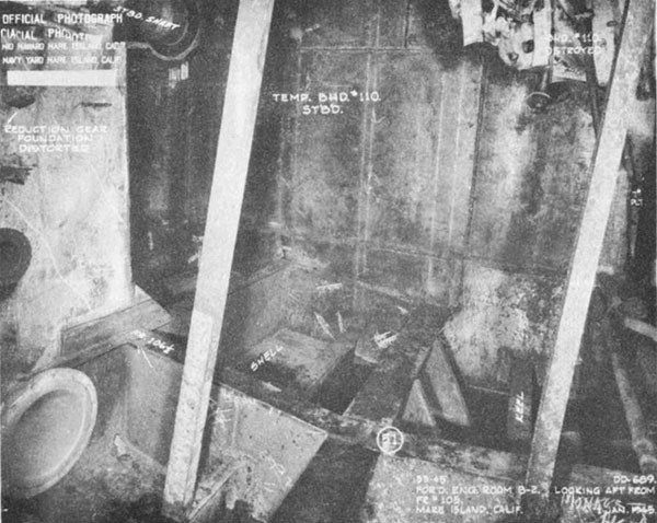
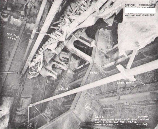
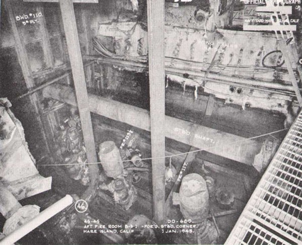
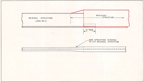
7. The first member installed was the keel plate. After three sections had been welded, the vertical keel which had been prefabricated in the dock basin was placed on the keel plate and welded with 1/2" continuous welds. Two 25" x 18" x 10# web brackets were installed, port and starboard, between adjacent web frames (Plate 21, Photo 43). Next, the continuous longitudinals and intercostal transverses were installed and welded (Plate 22, Photos 44 and 45). The ends of all existing longitudinals were cut back beyond the plating, the flanges were cut farther back and a 4-1 taper was used in connecting the webs and flanges of the new and replacement longitudinals (Plate 22, Photo 46). External longitudinals with web brackets at transverse frames and with tapered ends were installed in way of the wrinkle in F and G strakes, port and starboard.
8. Next, the plating was installed. The limited equipment available to handle and fit the plating made it necessary to use comparatively short lengths. No equipment for rolling or bending plate heavier than 15# was available, therefore, heavier plate was installed in flat sections. "A" strake was butt welded to the keel, all other seams were lapped, similar to the original plating (Plate 23, Photo 47). On the port side where wrapper plates were lapped over the crack, 12' long 6" x 30# flat bar longitudinals with tapered ends were fitted outside the shell (Photo 48). Since the original longitudinals in this area were riveted, it was necessary to fit the external longitudinals between the original ones to reduce the possibility of loosening the rivets. Sea chests in B-2-1 and B-2 were blanked to prevent leakage.
9. A partial bulkhead was built to replace the damaged portion of bulkhead 110 (Plate 21, Photos 44 and 45). A sloping transition piece was used to fair the new bulkhead into the original one below the main deck. The ends of the bulkhead stiffeners were bracketed. A gasket type stuffing box was installed where the starboard shaft penetrated bulkhead 110 (Photo 49). Damaged pipe stanchions between the shell and main deck were replaced by columns built up from two 8" channel sections with 10# webs added. (Photo 45).
--51--
--52--
--53--
--54--
--55--
--56--
--57--
--58--
USS NEWCOMB (DD 586)
| Ship: | USS NEWCOMB (DD 586) |
| Cause of Damage: | Four Kamikaze Planes (1 Bomb) |
| Date: | 6 April 1945 |
| Place: | Okinawa |
| Class: | FLETCHER (DD 445) |
| Standard Displacement: | 2100 tons |
| Length Overall: | 376' 5" |
| Extreme Beam: | 39' 7" |
| Draft Before Damage: | Not Reported. |
| Launched: | 4 July 1943 |
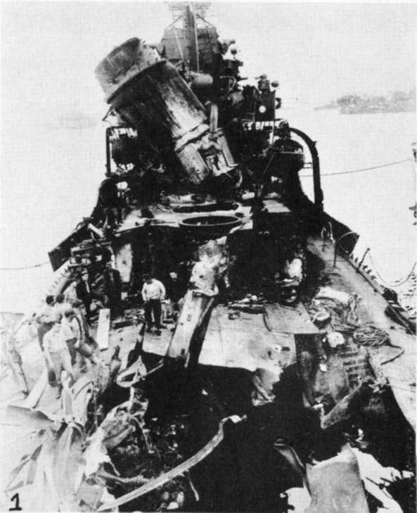
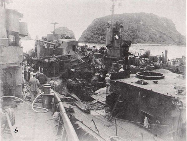
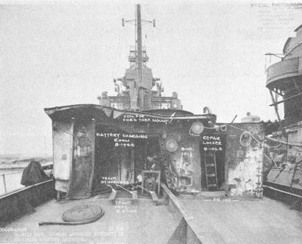
1. On 6 April 1945, NEWCOMB was serving as part of the screen for ST. LOUIS in support of minesweeping operations near Okinawa. Upon completion of this duty and while proceeding to rendezvous with a night retirement group, NEWCOMB was subjected to a concerted attack by seven Kamikaze aircraft. At 1800, one plane crashed into the after stack, putting the after fireroom out of operation and causing a fire in the upper handling room of 5" mount 3. Shortly thereafter, a second plane, carrying a bomb, crashed amidships in the vicinity of the torpedo workshop. The explosion of this bomb caused serious damage to both engine rooms, completely immobilizing the ship. The after stack, both torpedo mounts, amidship superstructure, 40 mm mounts and magazines were blown over the side (Photos 50 and 51). The main deck was ruptured between frames 108 and 135, the starboard side being blown upward and the port side downward. A fire raged throughout the after deckhouse and in the amidship area. A third plane crashed Into the forward stack and added gasoline to the amidship fire. At 1811, LEUTZE came alongside to assist In firefighting. At 1815, anti-aircraft fire caused a fourth plane to swerve from its course toward the bridge and to crash amidships and cross to LEUTZE's fantail where it exploded. At 1830, BEALE came alongside and passed over fire hoses. All fires were under control by 1900 and at 1930 all fires were extinguished.
2. Damage to the underwater body was as follows:
(a) The keel buckled at frame 120 over a length of two feet and projecting about six inches below the base line.
(b) A 5' x 2 1/2' hole at frame 119, six feet to port of centerline.
(c) Two 12" x 18" holes at frame 120 and 121, five and six feet to starboard of centerline.
(d) A 1' x 1' hole at frame 118, six feet to port of centerline.
--59--
(e) An 8" diameter hole at frame 119, one foot to port of centerline.
(f) A 6" diameter hole at frame 123, one foot to starboard of centerline.
(g) Numerous small projections of plating near frame 120.
(h) Leaking shell plating seams, frames 120 to 130.
3. The shell plating was slightly distorted on both sides between frames 100 and 140, the maximum being 6" at frame 120. Bulkheads 110 and 131 1/2 were destroyed so that B-2, B-3-1 and B-4 flooded to the waterline. Bulkhead 92 1/2 was seriously bulged and damaged, but was intact to within five feet of the main deck, so that there was only minor leakage into B-1-1.
4. At 2030 NEWCOMB was taken under tow for Keramo Retto, arriving there at 0930 the following morning. Initial salvage operations were directed toward stopping minor leaks, removing flood water, clearing debris in the damaged areas and establishing galley facilities to replace those destroyed by the fire. About one week later, NEWCOMB was drydocked and the following repairs were made:
(a) All holes in shell plating were covered over with 15# plate.
(b) All shell suction and discharge lines in B-2, B-3-1, and B-4 were blanked.
5. Other major structural repairs were:
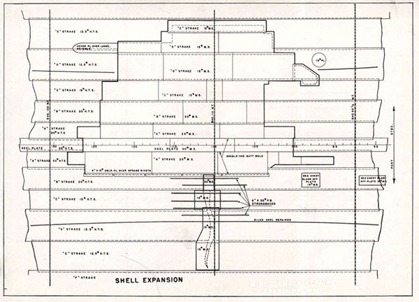
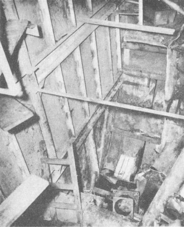
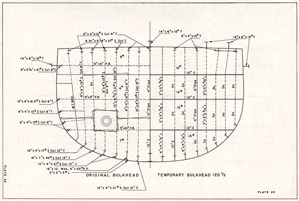
(a) A temporary transverse bulkhead was installed at frame 120 (Plate 24, Photo 52).
(b) 15# plate was used to repair web frames 130 and 133, port, and web frames 133 and 136, starboard.
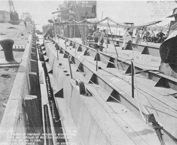
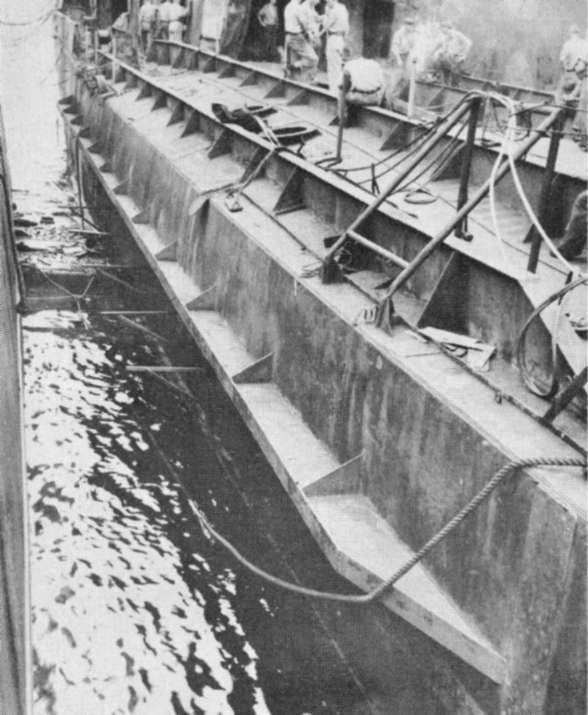
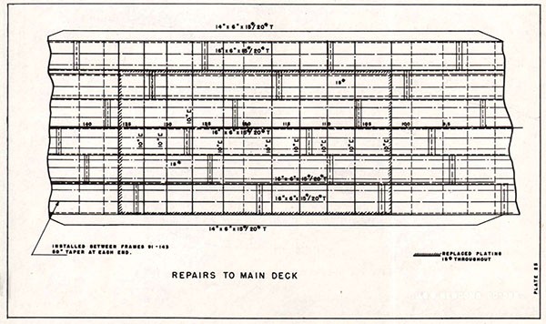
(c) The longitudinals under the missing portion of the deck were replaced by T's built up from 15# plate.
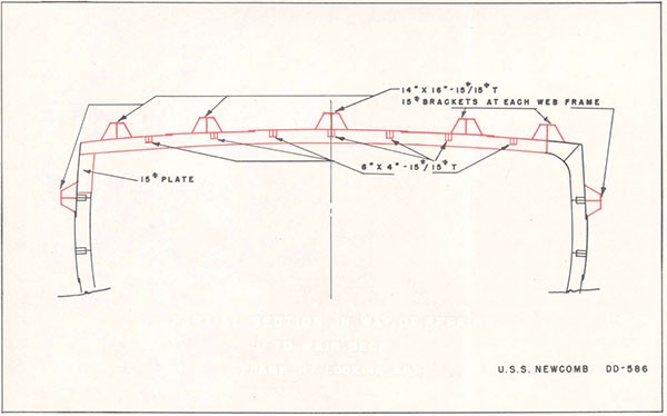
(d) The missing center portions of 9 web frames in way of the main deck were replaced by 10" channels (Plates 25 and 26).
--60--
(e) The damaged portion of the deck was replaced with 15# plate (Photos 55 and 54)
(f) The port and starboard sheer strakes were reinforced by 14"/6" x 15# /15# T's (Photo 55).
--61--
--62--
--63--
--64--
USS KEARNY (DD 432)
| Ship: | USS KEARNY (DD 432) |
| Cause of Damage: | Submarine Torpedo (One) |
| Date: | 17 October 1941 |
| Place: | North Atlantic |
| Class: | LIVERMORE DD 429 |
| Standard Displacement: | 1630 tons |
| Length Overall: | 348' 4" |
| Beam: | 36' 1" |
| Draft Before Damage: | Not known |
| Launched: | 9 March 1940 |
1. While KEARNY was escorting a convoy in the North Atlantic, a torpedo detonated at frame 72, starboard, about 8 feet above the base line. The explosion caused a hole in the shell about 20 feet long by 16 feet high (Plate 27, Photo 56). The 17-pound sheer strake was dished Inward, but did not fracture. The 25-pound starboard deck stringer plate bulged upward, but did not break. The strake of 8-pound plate inboard of the deck stringer was blown out. Fresh water tank B-5W was destroyed. The forward portion of B-7W, adjacent to the shell damage, was badly torn, but the remainder was substantially intact and the after portion was only moderately distorted. Structure on the port side of the ship was not damaged. After the attack, wind and sea conditions were favorable and KEARNY was able to proceed under her own power at a speed of 10 knots to Iceland, a distance of 400 miles.
2. When Informed of the damage and that KEARNY was proceeding to Iceland, VULCAN made plans for using a cofferdam to make repairs. An estimate was made concerning the material required for constructing a cofferdam and restoring hull strength. That on hand was insufficient for these purposes, therefore, plates and shapes were obtained from other ships present, and a few random size shapes and plates and 100 18-foot lengths of 4" x 8" yellow pine were obtained from sources ashore. The damaged side of KEARNY was brought alongside VULCAN on 19 October so that diving operations could be conducted in the lee between the two ships. The next few days were occupied with removing debris, water, fuel oil, etc. in preparation for repairs and to rehabilitate the damaged living quarters. The draft in way of the forward fireroom was reduced 12 inches by removing ammunition, stores, one anchor and chain. Diving operations were conducted as permitted by weather conditions and work on other ships. A section of the bilge keel in way of the after end of the caisson was cut away with an underwater cutting torch. Dimensions for
--65--
templates of the two ends and bottom of the cofferdam were lifted. The templates were constructed and checked to insure proper fit to the distorted shell plating.
3. The material available for constructing the cofferdam consisted of 100 18-foot lengths of 4" x 8" yellow pine, a limited supply of 1/2" wool felt, crews mattresses, canvas and odd lengths of various structural shapes. Over 1500 bolts, varying in length up to 18", were manufactured from 1/2" to 1" stock. Details of the cofferdam are shown on Plates 28 and 29. The outboard side was 4 feet from the shell plating at the top and 3 feet at the bottom. The space within was wide enough to permit plates to be lowered and to allow welding on the outside of the shell. The caisson was 36 feet long, with main frames every 9 feet. Planking was bolted to the frames and end sections. Brackets fabricated from 4" x 4" x 1/2" angle were bolted to the planking at intervals. One lifting pad backed up with 15-pound plate was bolted to the inside of each end of the caisson. Three straps fabricated from 3/8" plate were installed at the bottom for securing hogging lines to hold the cofferdam against the hull. Similar straps were provided at the top of the caisson at both ends. Turnbuckles, approximately 5' long, were secured to these straps and to pad eyes welded on the shell in order to adjust the cofferdam and hold it against the hull. Two longitudinal trusses were bolted 2 feet and 7 feet from the top of the caisson (Plate 29). They were fabricated mainly from 4" x 4" x 1/2" angle, but other available material also was used. Six braces of 2-1/2" x 4" x 1/2" channel, formed to fit the inside curvature of the cofferdam, were bolted to each plank. A tension rod of 2" x 1/2" strap was welded between the ends of each brace. All seams were caulked with oakum and the three bearing edges were covered with a three inch thick gasket made from felt or mattress stuffing covered with canvas. Wood two by fours, extending about three feet beyond each end of the cofferdam, were nailed in place and staging was provided at the lower edge for use of the divers.
4. After the caisson was completed and favorable weather conditions prevailed, KEARNY was breasted out by using a large camel and the ship was listed 18° to port. The cofferdam which weighed 11 tons was lifted, hogging lines were secured to the lower edge and water ballast was added. Chain falls rigged on the main deck, port side, were used to pull taut the hogging lines. When in position, the turnbuckles were shackled to the pad eyes on the side of the ship and the cofferdam was pulled tight. Divers, sent down to verify the correct position of the caisson, found that B strake in way of the lower edge of the cofferdam was
--66--
bent inward. Accordingly, a template was taken and a wedge 12' long and having a maximum width of 3" was made from felt covered with canvas. This was secured in place by strips of 4" x 1/8" plate, nailed with 5" boat nails. After this wedge had been installed, seven 200 GPM submersible pumps and one fire and bilge pump were started and the cofferdam seated immediately. The water level was lowered to just below B strake and staging was erected in the cofferdam. Once the water level was established, only one submersible pump was required to control the leakage. However, water pressure caused 5-inch deflection of the cofferdam. Therefore, when E strake had been fitted, a 6" x 12" wood shore was run between one of its supporting longitudinals and the steam drum of boiler 1. A second 6" x 12" wood shore was Installed between the outside of the plating and the cofferdam, and wedges were used between the shore and cofferdam to remove the deflection.
5. The extent of repairs to shell plating are shown on Plates 29 and 30. Strakes F and G, which were above the waterline, were repaired while the cofferdam was being constructed. Strake E was installed after the first lowering of water inside the caisson. Welding on the inside of strakes F and G proceeded simultaneously with that on the outside of strake E. When welding on strake E was completed, the water level was lowered so that work could proceed on strake F. Plates in this strake were rolled, and small fairing plates were used at the ends to connect to the new plating. All plates were tack welded and the bottom edges were held in place by chain falls secured to pad eyes. Welding was commenced at the center of the strake and proceeded towards the ends. When it had been completed, the caisson was pumped dry and work began on the closing strake C. Plates were lowered and pulled into place by chain falls inside the ship. After welding had progressed sufficiently to hold the plate rigidly, templates were lifted for the framing. Web frames were installed at frames 67, 70, 74 and 77. Intermediate frames and longitudinals were installed to duplicate the original structure as nearly as possible within the limits of the material available. The completed repairs were inspected for tightness as the caisson was filled slowly.
6. Repairs to the main deck (Plates 30 and 31) were undertaken after completion of those to the shell. A 25-pound stringer plate, stiffened by three 10" x 5" x 15#/15# built up I beams, was installed between frames 66 and 85. The next inboard strake was replaced by 15-pound plate.
--67--
7. Simultaneous repairs had been made to rehabilitate living spaces, overhaul machinery, restore the weathertightness of the deck house, replace damaged piping lines and establish communications throughout the ship. Bulkhead 67 was repaired. KEARNY attained a speed of 25 knots on a post repair trial and proceeded to the United States in company with a fast convoy.
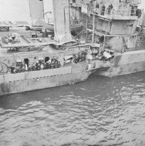
--68--
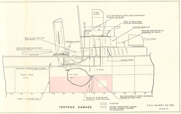
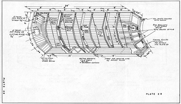
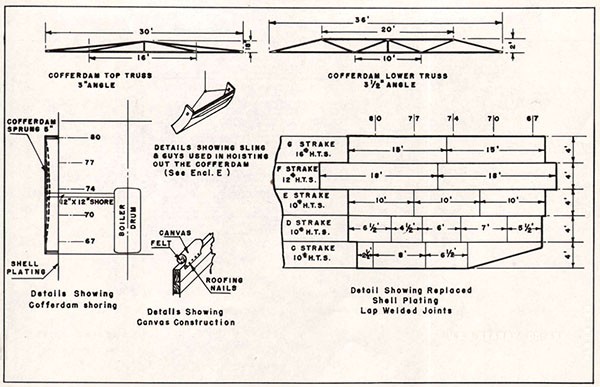
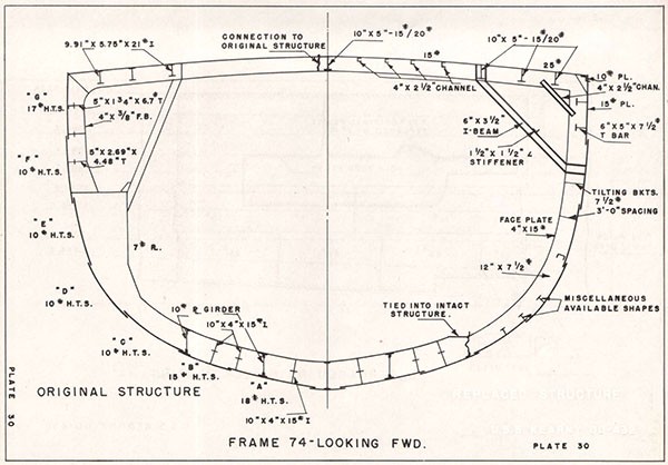
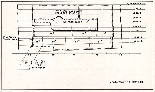
USS SELFRIDGE (DD 357)
| Ship: | USS SELFRIDGE (DD 357) |
| Cause of Damage: | 2 Torpedoes |
| Date: | 6 October 1943 |
| Class: | PORTER (DD 356) |
| Place: | Vella La Vella |
| Standard Displacement: | 1850 tons |
| Length Overall: | 381' |
| Extreme Beam: | 37' |
| Draft Before Damage: | 13' 3" |
| Launched: | 18 April 1936 |
1. On the night of 7 - 8 October 1943, SELFRIDGE was a unit of a task force assigned the mission of intercepting and destroying Japanese forces attempting to evacuate enemy troops from Vella La Vella Island. At 2300, SELFRIDGE had turned to engage a group of enemy destroyers. At 2305, two torpedoes were seen approaching from a relative bearing of 330°. The Commanding Officer maneuvered to avoid these and other torpedoes reported on the starboard bow. At 2306-1/2, a torpedo detonated at about frame 40, starboard. There was some indication that a second torpedo detonated almost simultaneously at frame 30, port. The bow severed completely at about frame 40 and floated aft on the starboard side. The extensive structural damage to SELFRIDGE Is shown on Plate 32 and Photos 57 and 58. The engineering plant was intact. About one minute after damage, the ship backed full until sternway was gained, then the engines were stopped. Damage control measures were effected and after 40 minutes, SELFRIDGE proceeded at 10 knots to Purvis Bay, a distance of 120 miles.
2. At Purvis Bay, where no drydocking facilities were available, repairs were undertaken by ARISTAEUS (ARB-1). Damage to fuel oil tanks had spread oil over most of the wreckage, and ammunition was present in the remains of the various magazines, handling rooms and hoists. Before undertaking burning or removal of any major portion of the wreckage, it was necessary to reduce the fire hazard. After this had been completed, all salvageable equipment and wreckage were removed. From the keel to second platform all structure forward of frame 51 was removed; between the main deck and second platform, structure was removed forward of frame 55; and above the main deck, all structure forward of frame 52-1/2 was removed (Photo 59).
3. The principal repairs were: (Photos 60 and 61)
(a) The transverse bulkhead at frame 59 between the first platform and main deck was partially replaced.
--69--
(b) Web frame 55 was repaired where necessary at the first platform and main deck levels. Stanchions were installed under it to support the superstructure.
(c) Shell plating and longitudinals were replaced between the first platform and main deck, frames 55 to 59, starboard.
(d) Bulkheads were reinforced in A-2F, A-3F, A-6F, A-7F, A-8F and A-11F. Cable trunks A-9T, A-10T, and A-208T were blanked.
(e) A temporary bow was installed above the first platform. The stem, fabricated from 15# plate, extended from frame 49 at the forecastle to frame 49-1/2 at the first platform. 10" center-line longitudinals were extended forward to meet the stem. At the forecastle and main deck levels these longitudinals were fabricated from 10# plate. A 10" I beam was used on the first platform. A 10" transverse web frame was constructed at frame 52 1/2 under the main and forecastle decks. Forward of this frame, the main and forecastle decks were completed with 7-1/2# plate. No deck was installed at the first platform level. The 10# flat shell plating of the temporary bow extended from the stem back to the shell at frame 55 (Photo 62).
(f) A temporary bulkhead of 7 1/2# plate was installed between the forecastle and superstructure decks at frame 53 to close the forward end of the deckhouse.
(g) An inclining experiment was conducted to verify the initial stability of SELFRIDGE.
4. On 23 November, SELFRIDGE got underway for Noumea, New Caledonia, arriving 1 December, There she was drydocked in ARD-2. The structure remaining below the waterline was trimmed to permit the use of straight structural shapes and flat plates in completing the temporary bow structure below the waterline. Bulkhead 55 was stiffened by installing a horizontal 10" I at the second platform level. The stem was made from a 10" I installed from the keel at frame 52 to the 1st platform. Similar girders were installed at the 2nd platform level from the center and ends of the I beams used to stiffen bulkhead 55 (Photo 63). Flat plating was then installed (Photos 64 and 65).
--70--
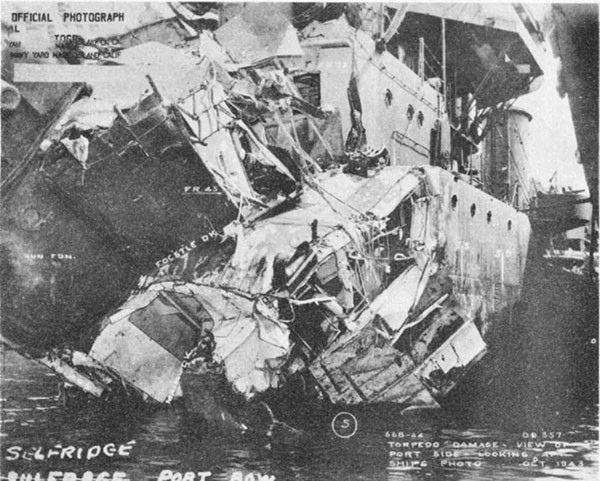
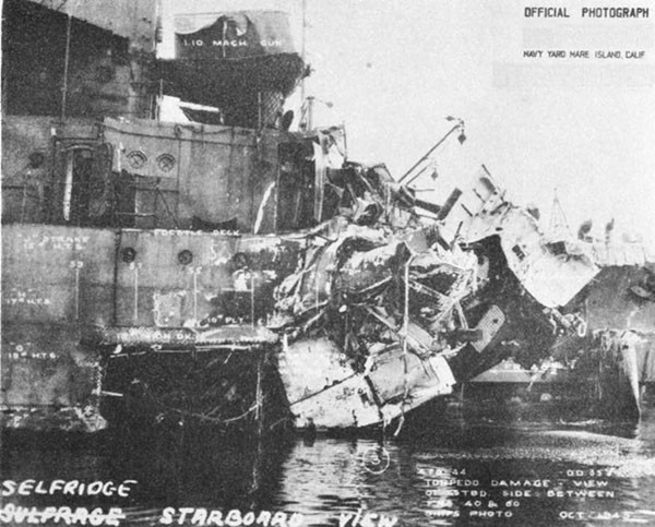
--71--
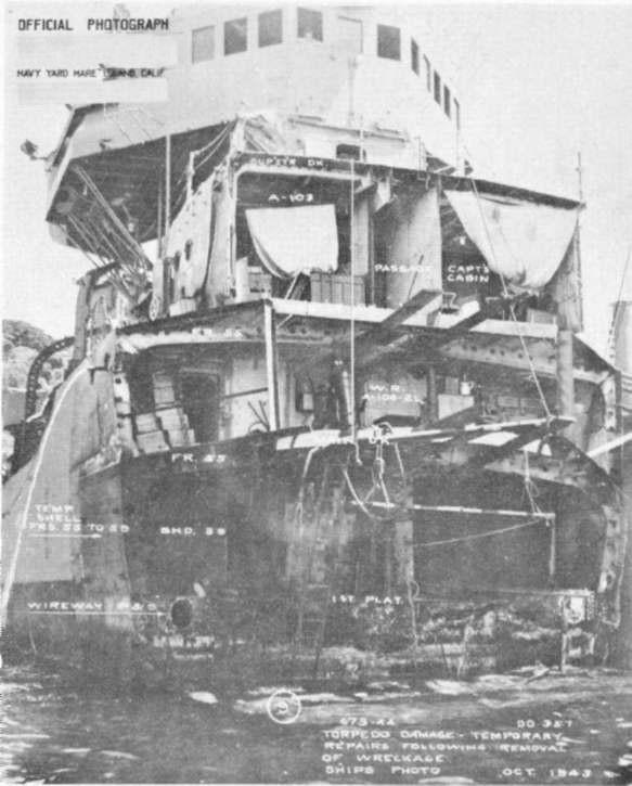
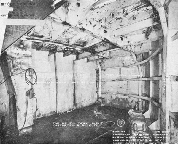
--72--
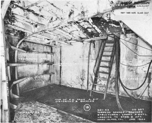
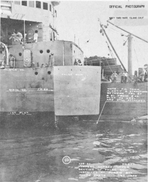
--73--
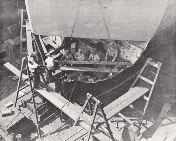
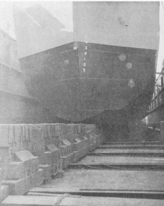
--74--
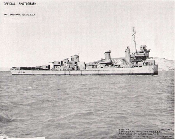
--75--
--76--
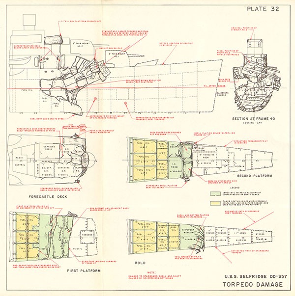
USS FOOTE (DD 511)
| Ship: | USS FOOTE (DD 511) |
| Cause of Damage: | Torpedo |
| Date: | 2 November 1943 |
| Place: | Empress Augusta Bay, Bougainville Is. |
| Class: | FLETCHER DD 445 |
| Standard Displacement: | 2100 tons |
| Length Overall: | 376' 5" |
| Extreme Beam: | 39' 7" |
| Draft Before Damage: | 13' 1" (Estimated) |
| Launched: | 11 October 1942 |
1. At 0301, 2 November 1943, a torpedo detonation at about frame 203 on the rudder skeg destroyed all structure aft of frame 196, deflected upward the hull remaining aft of frame 182, and bent both propeller shafts so that the engines had to be stopped immediately (Photo 66, Plate 33). The main deck was wrinkled deeply and cracked in six places between frames 166 port and 170 starboard. These wrinkles continued In the shell plating down to the turn of the bilge, and there were similar deep wrinkles in the shell plating at frame 163 (Photo 67). Considerable damage to shell plating near the stern tubes resulted before the shafts could be stopped (Photos 67, 68). Minor structural failure occurred at frame 30. Within two minutes, extensive flooding aft reduced the draft forward to 6' and caused a 5° port list that brought the deck edge aft of frame 172 flush with the water. By 0600 damage control measures undertaken by FOOTE had removed the list and restored 6" freeboard aft. FOOTE was taken under tow at 0638 and arrived at Purvis Bay, Florida Island, Solomon Islands at 1500, 4 November. En route, the freeboard aft had been increased 2" by cutting away 75 square feet of damaged main deck plating and jettisoning damaged equipment.
2. At Purvis Bay, where no drydocking facilities were available, WHITNEY (AD 4) made temporary repairs to improve strength and make FOOTE seaworthy for tow. Divers examined the underwater body thoroughly and established that the hull was intact forward of frame 157. Other measures undertaken were:
(a) Reduction of trim by stern. All forward fuel tanks and peak tanks A-1W and A-501W were ballasted. Five hundred 5" powder cans, filled with water, were placed forward of frame 30. Outboard shafting and propellers were removed. Most of the damaged structure aft of frame 182 was cut away (Photo 69). 5"/38 gun and mount
--77--
No. 5, and 5"/38 gun 4 were removed. 5"/38 and 40 mm ammunition were removed from the after magazines. All removable equipment, including electrical wiring, was taken from compartments C-203L and C-204L. Salvageable equipment, stores and spare parts were stowed forward for ballast.
(b) Restoration of buoyancy and watertight integrity. Simultaneously with the efforts to increase freeboard aft, the flooded compartments on the 1st platform were unwatered and made tight by welding, use of wooden plugs, etc. C-304M was unwatered and made watertight; C-301M was unwatered and leakage was reduced to about 50 gallons per hour, which could be controlled by available pumping facilities. Bulkhead 182 was made watertight above the 1st platform by welding a plate over the doors; installing additional welded stiffeners and shoring. Bulkhead 170 above the 1st platform was made tight by welding a plate over the doors and shoring. Bulkheads 157, 163, 170, 175, and 182 in the after magazines were snored.
(d) Restoration of longitudinal strength. 4" x 3"-20#/20# welded T stiffeners with tapered ends and web brackets were installed in way of damaged structure on the main deck and sheer strake, frame 154-176 (Plate 34, Photo 67). Four 3" x 20# flatbar stiffeners were welded on the main deck, frame 26-32.
3. FOOTE was taken under tow for Espiritu Santos on 23 November. En route, FOOTE yawed excessively, apparently as the result of removing the damaged structure aft. At Espiritu Santos, FOOTE was placed in drydock and the following repairs were made by DIXIE (AD 14).
(a) Additional longitudinal strength members were installed on the main deck (Plate 34).
(b) A stern cofferdam was added aft of bulkhead 182 (Plates 34 and 35, Photo 70).
(c) Two fixed fins were installed to improve towing characteristics (Plate 35, Photos 70 and 71). These fins were effective in preventing excessive yawing during tow to San Francisco.
(d) Flush, patches were welded over the damaged shell in the stern tube areas (Plate 36, Photo 72).
(e) Bulkheads 157, 170, and 182 were made watertight.
--78--
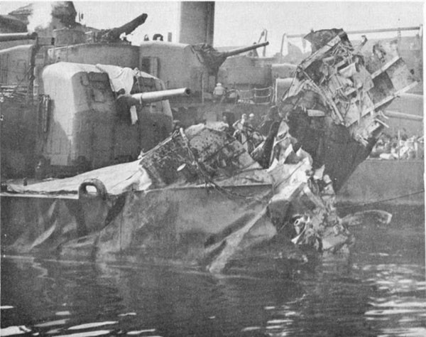
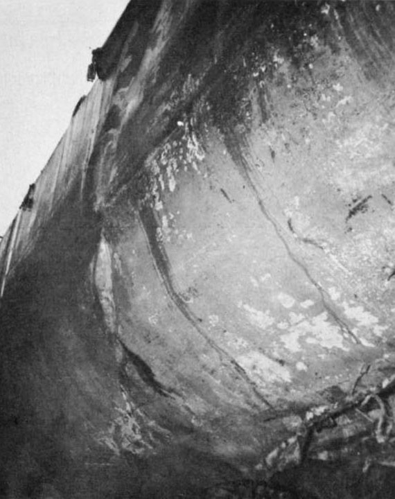
--79--
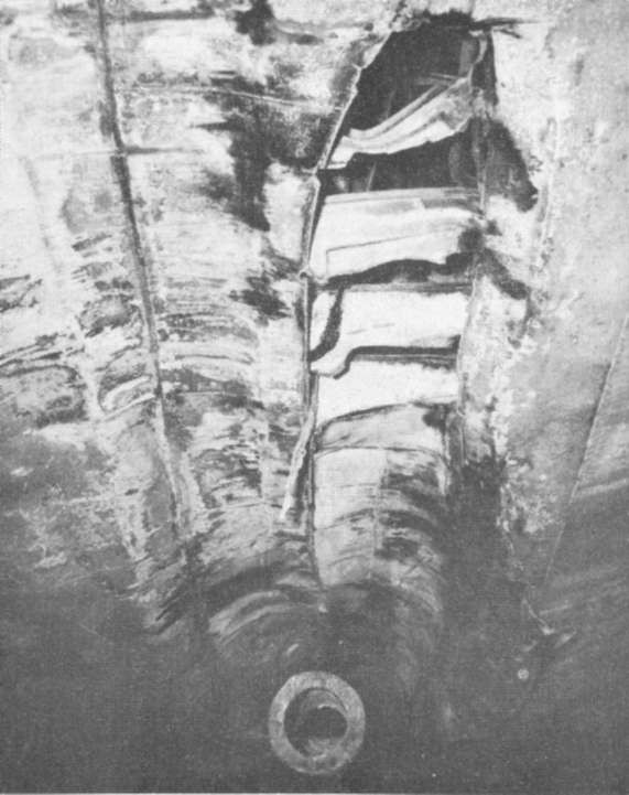
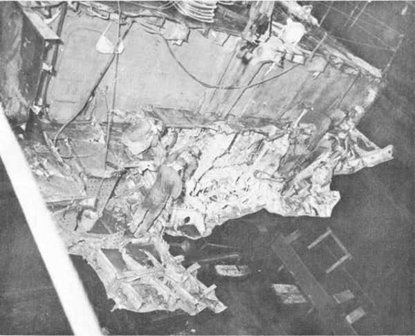
--80--
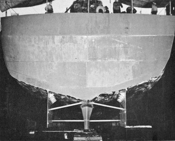
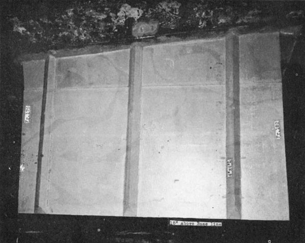
--81--
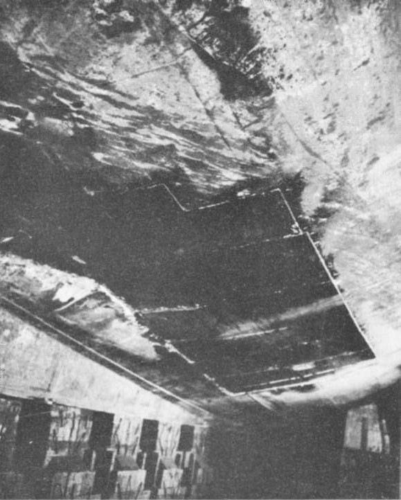
--82--
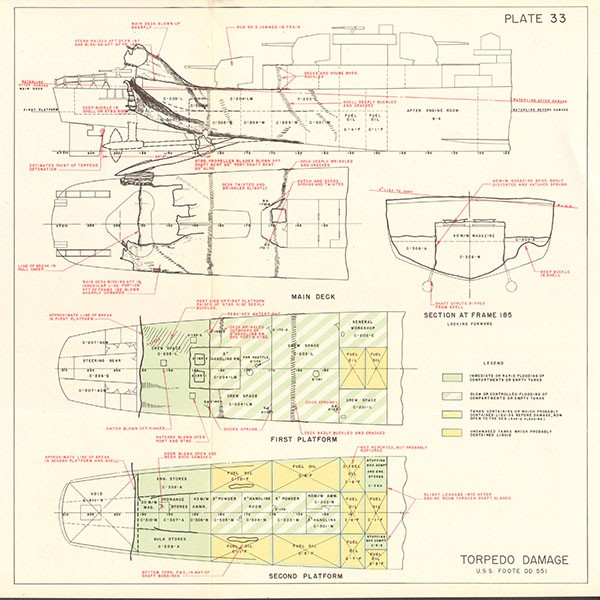
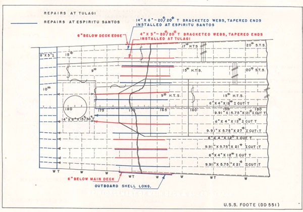
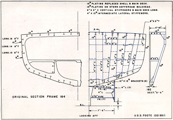
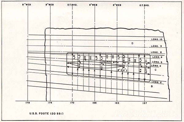
USS INTREPID (CV 11)
| Ship: | USS INTREPID (CV 11) |
| Cause of Damage: | Aircraft Torpedo |
| Date: | 17 February 1944 |
| Place: | Truk |
| Class: | ESSEX (CV 9) |
| Standard Displacement: | 27,100 tons |
| Length Overall: | 876' |
| Extreme Beam: | 147' |
| Draft Before Damage: | Not reported. |
| Launched: | 26 April 1943 |
1. A deep running aircraft torpedo detonated at about frame 194, just forward of the rudder, while INTREPID was making a port turn. Structural damage and flooding were moderate, but the rudder and steering gear were damaged beyond use or repair and the fairing piece over the counterbalance portion of the rudder was blown off (Photos 73, 74 and 75). The effect of the damage on ship control was equivalent to maintaining 6 1/2 left rudder. After considerable experimentation, including measures to reduce the drag aft and to provide sail area forward, the ship was able to proceed from Truk to Pearl Harbor using main engines for steering. While in drydock at Pearl Harbor, the damaged rudder was removed with the expectation that this would facilitate controlling the ship by use of the engines during the trip to San Francisco.
2. In order to reduce the tactical diameter of the CV9 class, the hull was designed with little deadwood, and directional stability was provided primarily by the rudder. After leaving Pearl Harbor with all rudder area removed, INTREPID was unmanageable. It was impossible to steady on any course and at times the ship would swing uncontrollably through 360°. Therefore, INTREPID was towed back to Pearl Harbor and again placed in drydock, where a non-watertight fairing patch was installed over the damaged shell plating (Photo 76) and a jury steering arrangement was provided.
3. An auxiliary centerline fin, equal in area to the original rudder, was installed. A 100 square foot section at the after end of the fin was hinged to serve as a jury rudder; this hinged portion having about 20% of the area of the original rudder (Photos 76, 77 and 78). The jury rudder could be rotated through a maximum angle of 20° right or left. It was controlled by wire cables which passed through a protecting pipe outboard of the shell and over sheaves at the deck edge on the fantail (Photos 77, 78 and 79). The ends of the rudder cables were secured to gun-tackle purchases, the running ends of which were taken to the after capstan (Photos 80 and 81).
--83--
4. It was originally intended that the jury rudder would provide directional stability and that steering would be done primarily by the engines. After leaving Pearl Harbor, steering with the engines was difficult and yaw could not be reduced below 40° to each side. It proved more satisfactory to overcome the effect of wind by adjusting engine revolutions and to use the jury rudder for steering. Full rudder gave the effect of about 5° of the original rudder. Despite 15 to 25 knot winds, yawing was reduced to about 10° on either side. Although the capstan starting panel was not designed for continuous operation as is required for steering, frequent cleaning of the contactors prevented excessive arcing. Special arrangements for lubricating the capstan shaft were made by INTREPID. Passage to San Francisco was made at 15 knots without further difficulty.
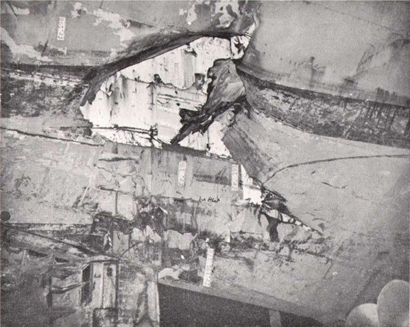
--84--
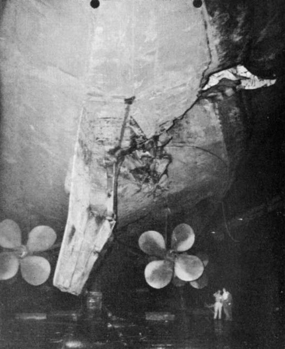
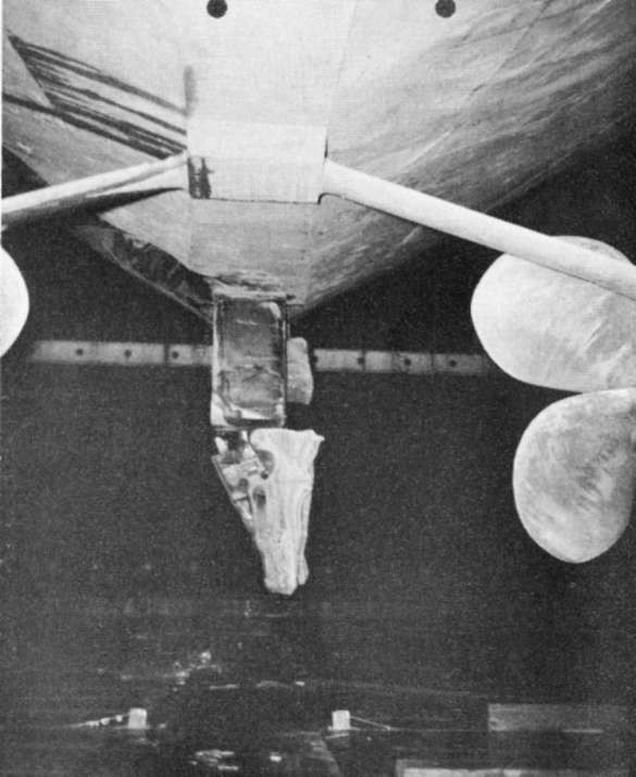
--85--
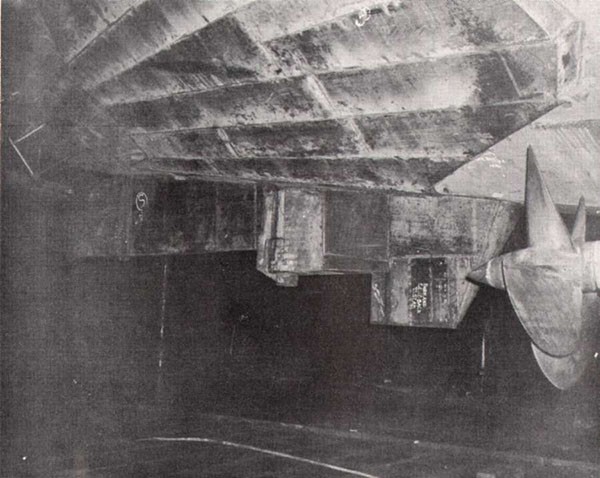
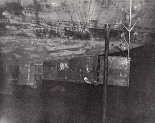
--86--
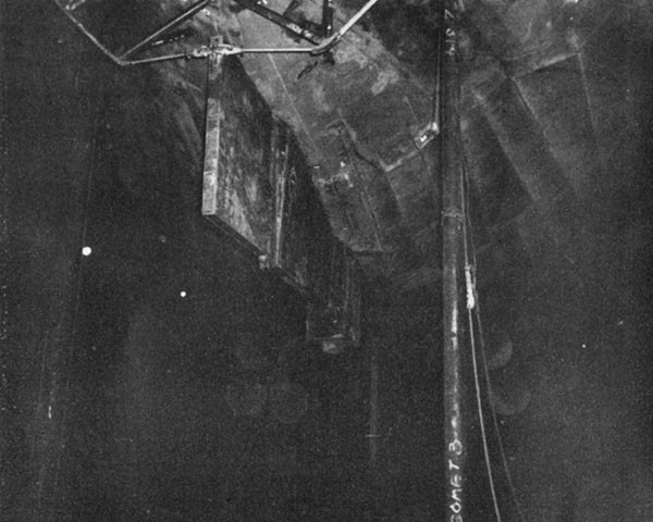
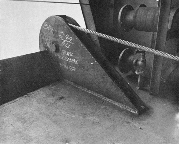
--87--
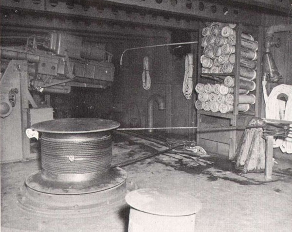
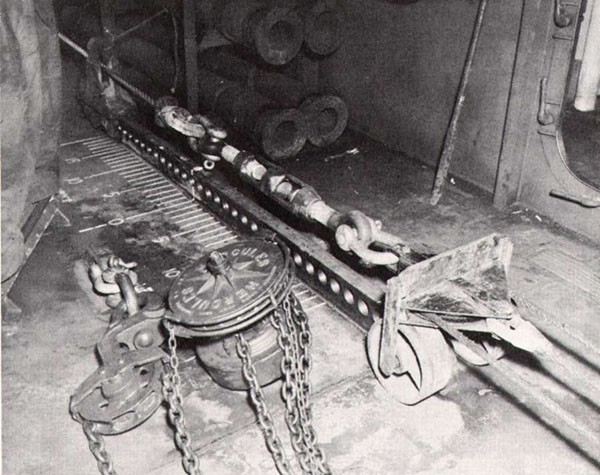
--88--
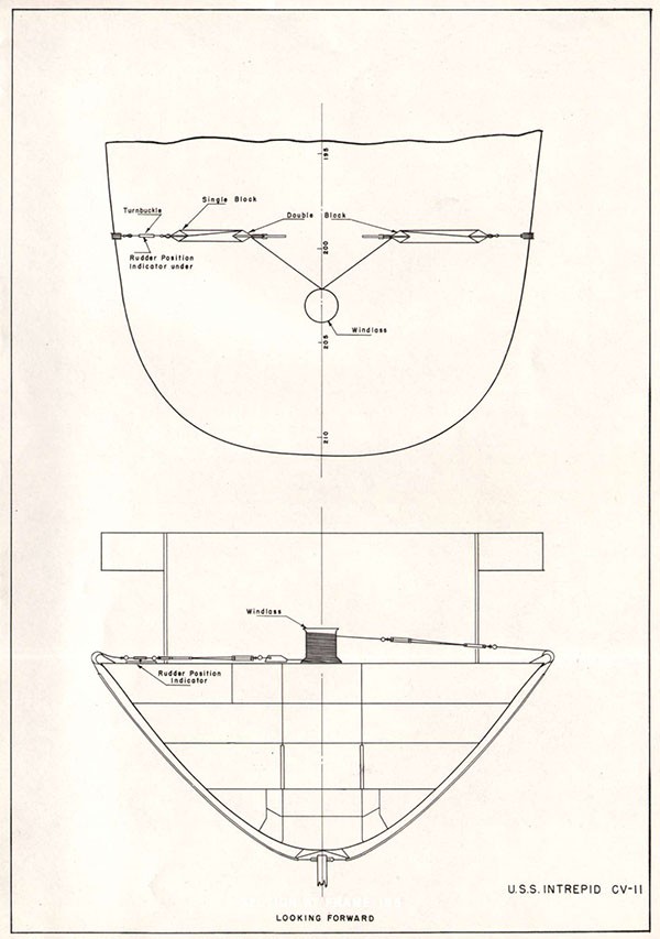
VIBURNUM (AN 57)
| Ship: | VIBURNUM (AN 57) |
| Cause of Damage: | 1 Mine |
| Date: | November 1944 |
| Class: | AN 38 |
| Standard Displacement: | 1275 tons |
| Length Overall: | 194' 6" |
| Extreme Beam: | 37' 0" |
| Draft Before Damage: | 11' 6" forward; 13' 6" aft |
| Launched: | 26 April 1944 |
1. VIBURNUM, a wooden hull ship, struck a contact mine at frame 12 starboard. The explosion tore a hole In the shell between frames 6 and 17 starboard and from the keel to the second deck side longitudinal (Photo 82), tore a hole In the second deck and in the port side of the main deck (Photo 83). The keelson (Photo 84) and planking about 3 feet to port were shattered between frames 7 and 18. The bolts pulled loose In connections between the shell and all bulkheads forward of frame 30. All spaces forward of bulkhead 30 flooded to the waterline as the ship took on a draft of 21 feet forward; 10 feet aft.
2. The crew undertook salvage measures that succeeded in reducing the drafts to 17' 6" forward and 12' aft. In order to accomplish this, the horns were cut off and moved to the fantail, the anchor chains were moved aft, debris was removed from the damaged spaces forward, and A-1W and the space between bulkheads 27 and 30 were made tight so that the spaces could be pumped dry. This made it possible to drydock VIBURNUM in ARDL 32 (Plate 38).
3. After VIBURNUM was drydocked, debris and damaged planking was cleared away and repairs were undertaken. Since neither materials nor trained personnel required to effect wood repairs were available, it was necessary to use steel. The keel was encased in 3/4" steel plate, which was bolted to it and extended well beyond the ends of the damage in order to provide structural continuity. The box structure surrounded the keel completely on the starboard side (Photo 85), but terminated on top of the port bilge celling (Photo 86). Bolts through the shell plating were used in conjunction with bolts through the wood structure to attach the steel box (Photo 87).
4. Transverse framing in the damaged area was replaced by fabricated steel T sections (Plate 30). The lower end of these frames were welded to the box girder encasing the keel structure. Their upper ends were welded to 12" H sections that were Inserted and bolted through the lower
--89--
deck shelf and lodger between frame spaces (Photos 88 and 89). Shell plating was welded to the steel keel box girder and to the frames. It was welded to the bow sheathing at the forward end. Other boundaries overlapped and were bolted to undamaged wood structure. A canvas gasket impregnated with red lead was used to make connections between wood and steel hull structures watertight (Photo 90).
5. The damaged portion of the lower deck was replaced by a steel deck. Deep I beams were used to replace the longitudinal 9" x 9" timber girders and served as intermediate supports for transverse channel sections which terminated in specially designed structure that landed on the lower deck shelf and was bolted to the lower deck lockstrake (Photos 91 and 92), The replacement of the main deck was similar to that of the lower deck, with deep longitudinal I girders replacing the 9" x 9" longitudinal timbers. Transverse channels were landed on the main deck shelf and were given intermediate support by the longitudinals (Photo 93). Pipe stanchions were installed between the hold, lower and main decks to provide additional support.
6. Although these repairs were intended to enable VIBURNUM to proceed to a mainland yard, they proved so successful that the vessel continued to serve in the forward area for the duration of the war.
--90--
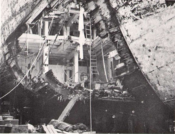
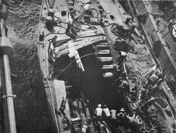
--91--
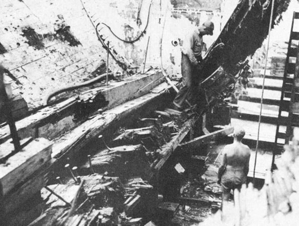
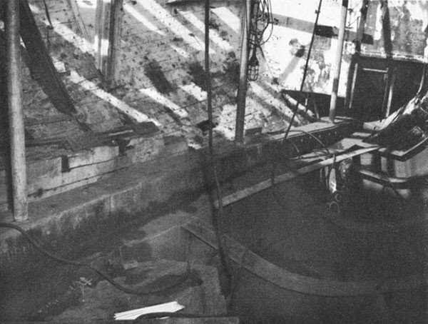
--92--
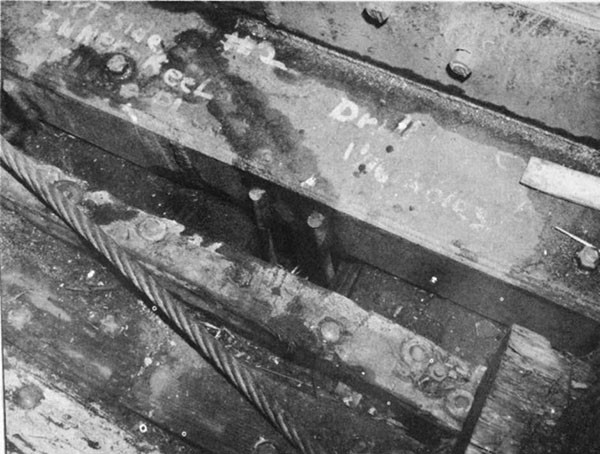
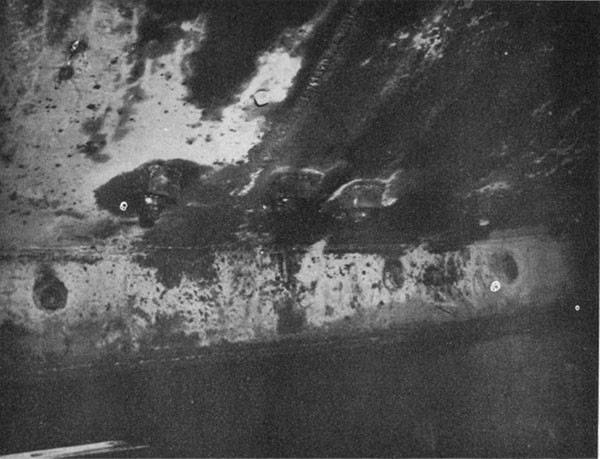
--93--
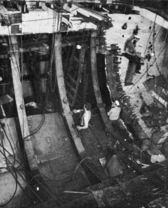
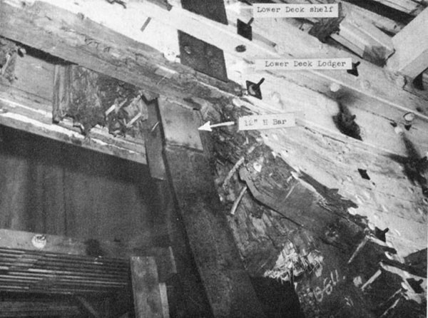
--94--
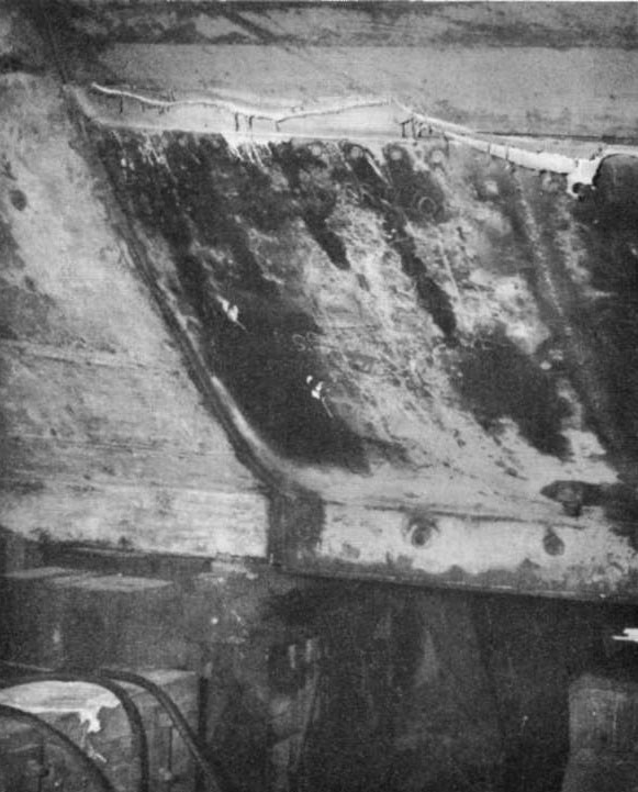
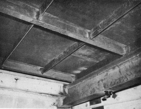
--95--
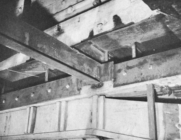
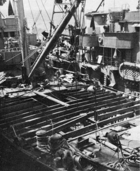
--96--
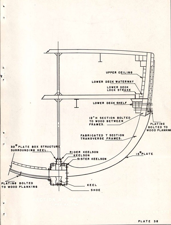
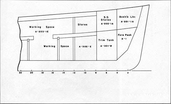
[END]
