The Navy Department Library
Ship to Shore Movement

General Instructions for Transports,
Cargo Vessels, and Landing Craft
of Amphibious Forces
In Two Parts
Part 1-- [formerly] CONFIDENTIAL [now declassified]
Part 2-- [formerly] RESTRICTED [now declassified]
HEADQUARTERS OF THE COMMANDER IN CHIEF
UNITED STATES FLEET
JANUARY 1943
United States Government Printing Office Washington, 1943
HEADQUARTERS OF THE COMMANDER IN CHIEF,
UNITED STATES FLEET.
January 18, 1943.
- It is considered highly desirable, because of frequent transfers of units between fleets, that a single procedure, uniform in its essentials, be adopted for the ship-to-shore movement in the various Amphibious Forces of the Navy.
- "Transports and the Ship to Shore Movement," prepared by ComTransAmphForLant, and "Ship to Shore Movement," prepared by ConTransAmphForPac, were carefully reviewed and form the sources from which a single version was prepared.
- "Ship to Shore Movement," U.S. Fleet, (FTP 211) is herewith issued for the guidance of the Amphibious Forces, U.S. Navy. It supersedes all similar publications by whomever issued.
- Recommendations for changes, based on operating experience, are solicited.
- Part 1 of this publication is [formerly] CONFIDENTIAL [now declassified] and shall be safeguarded in accordance with the provisions of Article 76, United States Navy Regulations. When no longer required, it shall be destroyed by burning. No report of destruction is required.
R.S. EDWARDS,
Chief of Staff.
(III)
Contents
| PART 1--[formerly] CONFIDENTIAL [now declassified] | ||
|---|---|---|
| Chapter | Page | |
| I. | General | 1 |
| II. | Characteristics of Landing Boats | 2 |
| III. | Debarkation | 5 |
| IV. | Landing Boat Organization; Duties of Landing Boat Commanders; Tactical Control of Troops | 12 |
| V. | Control Vessels | 16 |
| VI. | Traffic Control During Landing Operations | 18 |
| VII. | Naval Platoon of the Shore Party | 19 |
| VIII. | Communications | 29 |
| PART 2--[formerly] RESTRICTED [now declassified] | ||
| IX. | Hydrographic and Beach Markings | 77 |
| X. | Landing Boat Material | 81 |
| XI. | Landing Boat Operating Instructions | 95 |
| XII. | Salvage Craft and Operations | 99 |
| XIII. | Casualty Handling | 102 |
(V)
Source: A photocopy of this document is in the Navy Department Library. The original document is located in the World War II Command File of the Operational Archives Branch, Naval History & Heritage Command.
Chapter I. General
- Transports and cargo ships.--
- In this pamphlet naval vessels which have been specially converted for transportation and landing of assault troops (Army or Marine Corps) will be referred to as "combat unit loaded transports" in order to differentiate them from other naval transports.
- Combat unit loaded transports (APA's) and combat unit loaded cargo ships (AKA's) are normally assigned to the Amphibious Forces, United States Fleet.
- Purpose.--APA's and AKA's are designed to furnish transportation to assault troops and their equipment and to disembark them on hostile shores in the face of enemy resistance in the least possible time.
- Troop personnel usually assigned to combat unit loaded transports.--
- Troop personnel usually assigned to a combat unit loaded transport will consist of a battalion of infantry with reinforcing units suitable for the accomplishment of a given task. Reinforcing units usually consist of artillery, tanks, antiaircraft weapons, antitank weapons, shore party, medical unit, motor transport unit.
- The transport division of several APA's and one or two AKA's should normally carry a reinforced regiment plus a proportion of division troops.
- Landing boats.--As used herein, the term "landing boats" includes all craft designed for landing operations which are ship-borne. The term "landing craft" is used for all craft designed for landing operations which are less than 200 feet in length and not ship-borne.
Chapter II. Characteristics of Landing Boats
- Characteristics table.--A table of characteristics will be found on the following pages. Paragraph 202 contains data on fuel consumption.
| TABLE OF CHARACTERISTICS |
|---|
Notes: |
| Type A |
Desig. letter B |
Capacity C |
Draft D |
Weight E |
Armor F |
Arma- ment G |
Speed (miles per hour) H |
Endur- ance (miles) I |
Length J |
Beam K |
Crew L |
| Pounds | |||||||||||
| 1. Landing craft, rubber (small) |
LCR(S) | 7 troops | 210 | None | None | 12 feet, 5 inches |
5 feet, 8 inches |
None | |||
| 2. Landing craft, rubber (large) |
LCR(L) | 10 troops | 1320 | None | 1 .30 caliber machine gun |
4-5 with 91/2 horsepower outboard motor. |
16 feet | 8 feet | Do. | ||
| 3. Landing craft, personnel (plastic) |
LCP(P) | 13 troops |
10 inches |
1,400 | None | None | 20 | 32 feet | 7 feet, 10 inches |
||
| 4. Landing craft personnel (large) |
LCP(L) | 30-36 troops; or 6,700-8,100 pounds cargo (depending on fuel load) |
3 feet | 12,500 | 3 transverse bulkheads, 1/4-inch |
2 .30 caliber machine guns |
10 | 80 or 200 | 36 feet | 10 feet, 8 inches |
3 |
| 5. Landing craft, personnel (ramp) |
LCP(R) | 30-36 troops; or 6,700-8,100 pounds cargo (depending on fuel load). |
3 feet | 12,5000 | 3 transverse bulkheads, 1/4-inch |
2 .30 caliber machine guns |
10 | 80 or 200 | 36 feet | 10 feet, 8 inches | 3 |
| 6. Landing craft, vehicle- personnel |
LCVP | 36 troops or 1 1-ton truck of 8,100 pounds cargo (hold 18 feet, 3 inches x 6 feet, 3 inches) |
3 feet, 2 inches |
17,850 | 1/4 sides and ramp |
2 .30 caliber machine guns |
10 | 100 | 36 feet, 4 inches |
10 feet, 9 inches |
4 |
| 7. Landing craft, vehicle |
LCV | 36 troops or, 1 1-ton truck, or, 10,000 pounds cargo (hold 18 feet, 5 inches x 6 feet 3 inches) |
3 feet | 13,000 | None | None | 10 | 80 or 200 | 36 feet, 4 inches |
10 feet 91/2 inches |
3 |
| 8. Landing craft control |
LCC | Crew only | 4 feet | 50,000 | 1/4 inch bridge |
3 twin .50 caliber machine guns |
15 knots | 500 | 56 feet | 15 feet | |
| 9. Landing craft support (small) |
LSC(S) | 3 or 4 persons in addition to crew and gunners |
3 feet | 20,000 | 1/4 inch | 2 .50 caliber, 3 .30 caliber machine guns |
16 | 60 | 36 feet 6 inches |
10 feet 9 inches |
6 |
| Long tons |
|||||||||||
| 10. Landing craft mechanized, Mark II |
LCM(2) | 1 light (131/2-ton tank; or, 30,000-pound cargo; or 100 troops |
3 feet | 25 | Control station, 1/2 inch |
2 .50 caliber machine guns |
8.5 | 75 | 45 feet | 14 feet | 4 |
--2--
| 11. Landing craft,2 mechanized, Mark III |
LCM(3) | 1 medium (30-ton) tank; or 60,000 -pound cargo or 120 troops. (Cargo area 32 feet x 9 feet 7 inches, average) |
3 feet 6 inches |
22 | Control station, 1/4 inch |
2 .50 caliber machine guns |
10 | 125 | 50 feet | 14 feet | 4 |
| 12. Landing craft tank, Mark V | LCT(5) | 3 heavy (50-ton) tanks; or 5 medium (30-ton) tanks | 3 feet 1 inch fwd., 3 feet 9 inches aft | 124 | Control station, 1/4 inch | 2 20-mm. guns | 10 | 500 | 108 feet, O.A.; 105 B.P. | 32 feet | 1 officer, 10 enlisted |
| 13. Landing craft, infantry (large) | LCI(L) | 192 troops or 75 tons cargo | 2 feet 6 inches fwd., 4 feet 6 inches aft | 216 | 1/4 inch sides fwd.,3/8 bridge shield | 4 20-mm. guns | 17 knots | 4,000 (ocean) (500 landing) | 158 feet 4 inches O.A. | 23 feet 3 inches | 2 officers, 21 enlisted |
| 14. Landing ship, dock | LSD | 195 troops and 14 LCM(3) loaded (or 3 LCT(5) loaded) and 10 trucks on deck; or 1,500 longs tons cargo | 14 feet 6 inches | 5,850 | Splinter | 1 3"/.50 gun; 8 20-mm. guns | 16 knots | 8,000 at 15 knots | 457 feet 9 inches | 72 feet | 200 |
| 15. Landing ship, tank | LST | 186 troops and 10 heavy (50-ton) or 20 medium (30-ton) tanks or 39 light tanks (13-ton) | 3 feet fwd., 9 feet 4 inches aft | 1,412 | do | 6 20-mm. guns | 11 knots | 5,000 | 328 feet | 50 feet | 7 officers, 57 enlisted |
1. Without motor.
2. Higgins Type.
--4--
202. Fuel consumption.--Gallons per hour (top speed)
| Hall-Scott | Gray | Superior | Chrysler | |
| LCP(L); LCP(R); LCV | 24.5 | 15.6 | 7.6 | 11.3 |
| LCS(S) | 24.5 | |||
| LCM(3) (note 3) | 31.2 | |||
| LCC (note 4) |
Gallons per miles (top speed)
| Hall-Scott | Gray | Superior | Chrysler | |
| LCP(L); LCP(R); LCV | 1.76 | 1.26 | 0.73 | 1.08 |
| LCS(S) | 2.82 | 1.73 | ||
| LCM(3) (note 3) | 2.52 |
Note 1.--Speed Maximum:
| Miles per hour | |
| Hall-Scott | 14.0 |
| Gray | 12.5 |
| Superior | 10.5 |
| Chrysler | 10.5 |
Speed of boats equipped with Superior Diesel estimated. Other speeds taken from actual tests with full power and full load. |
|
Note 2.--Radius loaded:
| Fuel capacity, 300 gallons | Engine | Fuel capacity, 180 gallons |
| 206 miles | Hall-Scott | 100 miles +. |
| 242 miles | Gray | 100 miles +. |
| 417 miles | Superior | 100 miles +. |
| 333 miles | Chrysler | 100 miles +. |
Note 3.--Powered with Gray Diesel engine. These tank lighters will probably be powered with other types of engines in immediate future.
Note 4.--No information as to fuel consumption--maximum speed, at least 15 knots.
--4--
Chapter III. Debarkation
- General.--The ship-to-shore movement covering the planning and execution of the movement of troops from the beginning of their debarkation from transports until they are landed on the beach is well covered in chapter IV of FTP 167. This chapter is concerned with the task organization composed of the landing boats in which the landing force is to move ashore in assault. The following instructions are intended to supplement FTP 167, with which all persons connected with the ship-to-shore movement must be familiar.
- Battle condition.--
- Upon approaching the transport area all APA's and AKA's will go to general quarters. When the transport area is reached, set Condition One ABLE for the debarkation.
- Condition One ABLE (1A) is that condition of readiness in APA's and AKA's when all stations are fully manned for debarkation and unloading while at the same time the vessel is maintained in Condition One, insofar as available personnel permit. Services of the embarked troops will be made available to augment the ship's company, not to interfere with debarkation schedules.
- Transport area positions.--A position in the transport area is assigned each transport and cargo vessel. upon arrival at designated positions, transports and cargo vessels will anchor or lie to underway depending on wind and sea conditions prevailing at the time. See articles 142, 219-233 of FTP 167.
- Boat assignments.--
- It is the duty of the commander of the transports in a task group to furnish is corresponding troop commander with a boat availability table. This should indicated clearly which boats can be rail-loaded.
- If it can be accomplished, the dispatching of boats to another transport should be limited to an adjacent vessel under conditions of reduced visibility.
- If it can be accomplished, it is sound practice for a transport carrying a reserve battalion, to retain its boats for instant use by that battalion, augmented as required from the transport carrying the regimental headquarters.
- Experience has indicated that the average APA and AKA paired have sufficient boats for landing a reinforced battalion in assault. After providing for two assault battalions in this manner, the normal transport division would therefore rely on the two remaining APA's for prompt landing of the reserve battalion.
- Lowering boats.--
- Upon arrival at designated points in the transport area, APA's are stopped and, when directed, all boats are put over as expeditiously as possible. Sea conditions permitting, this should be by simultaneous lowering on both sides. If sea conditions are such as to require a lee, port boats will be lowered first. As a matter of policy, vessels which can lower tank lighters and heavy equipment from but one side will use the starboard side for this operation.
- Those vessels equipped with suitable davits and landing craft approved for lowering in loaded condition will habitually debark troops by lowering loaded from the rail.
- The purpose of loading at the rail and lowering loaded is to shorten the debarkation time. This purpose will be defeated unless all measures for coordination and speed are carefully undertaken. Troops and equipment of the first boats to be lowered from the multiple bank davits may, when desirable, be loaded while the transports are still underway so that the lowering of this group may commence immediately on arrival in the transport area. Troops in the first boats so lowered should include, if possible, all those intended for the first wave. Subsequent boats lowered from the multiple bank davits should likewise be preloaded and include troops and equipment which follow in normal sequence the order of landing. Arrival in the transport area should be so timed as to ensure the minimum interval between the commencement of lowering
- Stations for rail-loaded davit boats.--
- Troops assigned to a davit boat will assemble inboard of the boat, when possible.
- Ladders or gangplanks must be provided as necessary to expedite the loading of boats.
- Immediately on being lowered, loaded boats will proceed to the rendezvous area where they will join up by boat divisions and form the landing waves.
- Lowering details.--Each APA and AKA will organize permanent details for lowering all landing craft. See paragraphs 426 and 429(a) of FTP 167.
--5--
- Loading alongside.--
- Boat assembly areas.--As soon as unloaded boats are in the water, they proceed to the boat assembly areas. The location of these areas is as follows:
- When debarking simultaneously from both sides.--For LCP, LCV, and LCVP, two boat assembly areas, one on each quarter at 250 yards distance. These boats take station in the area corresponding to the side from which they were lowered, either from the parent or another vessel. For LCM and any larger craft assigned, astern, clear of the quarter assembly areas but within effective visual signal distance.
- When debarking from one side only.--For LCP, LCV and LCVP, one assembly area 250 yards distant on the starboard quarter. For LCM, one assembly area on the starboard beam. Any larger craft assigned, astern.
- Boats will circle at reduced speed in the following directions:
- Boats on starboard quarter and astern will circle in a clockwise direction while waiting to be called alongside.
- Boat on the port quarter will circle in a counterclockwise direction while waiting to be called alongside.
- Boats on the starboard beam will circle in a counterclockwise direction.
- An officer will be designated to take charge of the assembly circles. He will see that assembly circles are properly formed and maintained and that signals received from the ship's debarkation officer are promptly obeyed.
- All boats in the assembly areas will maintain a sharp watch on the after signal station for signals to come alongside.
- When boats from other vessels are assigned to an APA, they will join the appropriate assembly areas and assume automatically the status of the parent transport's own boats. Any boat officer from other vessels will act only as assistants to the assault wave commanders.
- Debarkation stations.--Troops (other than those lowered in boats) debark by debarkation nets over the side of the ship at debarkation stations. Each APA should have not less than four debarkation stations on each side. Each AKA should have not less than two per side. Debarkation stations are designated by number and color from forward to aft as follows:
Starboard Port Color Debarkation station No. 1 No. 2 Red. Do No. 3 No. 4 White. Do No. 5 No. 6 Blue. Do No. 7 No. 8 Yellow. Do No. 9 No. 10 Green.
- Boat assembly areas.--As soon as unloaded boats are in the water, they proceed to the boat assembly areas. The location of these areas is as follows:
--6--
g. The following considerations govern the location and rigging of debarkation stations.
- Deck adjacent to station as spacious and free of obstructions as possible to facilitate standing-by and passage of troops over the side.
- Ship's side to be approximately vertical and without excessive flare such as exists under the bow or counter.
- Stations should be separated as necessary in order that routes for troops moving from "boat load" assembling places below decks do not cross.
- Afford proper securings for the nets.
- Provide handrail for the troops to grasp when climbing on the net.
- Sea painters and boat lines should be provided for each station.
- The foot of the cargo net should extend to one foot below the load water line.
- The head of the debarkation net should be neatly secured at the edge of the deck without bulkiness, doubling or folding.
- Nets should be held spread by 4x4 beams lashed in place between the net and the side of the ship. The lowest spreader should be about seven feet above the foot of the net. Additional spreaders should be inserted as necessary to maintain the net at uniform width throughout its length.
- Two lines to the lower corners of the debarkation net, tended on deck, will facilitate debarkation and prevent the fouling of boat's propellers. This is accomplished by raising the bottom of nets prior to arrival and departure of boats.
h. The location of stations for the unloading of vehicles and cargo will be governed by the following factors:
- Station must be located adjacent to hatches.
- The radius of the cargo booms.
- Vehicles crews must debark at their loading stations.
I. Loading boats.--
- Debarkation stations operating instructions.--
- Special details.--
- A ship's officer, trained as debarkation officer, will be stationed on the bridge. He will be in general charge of the unloading and his primary task is to have the proper type of boat at a debarkation station ready for loading of boat when required. He is furnished by the commanding officer of the embarked battalion, a debarkation schedule, which indicates what type boat is to be at debarkation station at any time. He also keeps a check-off list of boats loaded and dispatched.
- A ship's officer will be stationed at the after signal station which is so located as to be clearly visible to all boats in the assembly areas. His duty is to order boats from the assembly areas to debarkation stations.
- A ship's officer or qualified petty officer and a troop officer will be stationed at each debarkation station. In addition to the duties given in paragraph 429d(1) of FTP 167, the ship's officer or petty officer is responsible for keeping the debarkation officer informed of the following:
When ready for a boat.
When boat is almost loaded.
When the loaded boat departs and its number. - An enlisted man trained in debarkation signals will be stationed at each debarkation station, and a signalman at the after signal station.
- A radioman who is in communication with the boat group commander and assistant boat group commander will be stationed with the debarkation officer.
- The debarkation officer will maintain direct communication with the after signal station and with each debarkation station.
--7--
- Special details.--
b. Calling alongside.--The following designating letters and numbers shall be used for calling the various types of boats alongside:
| LCP(L) | Love. | |
| LCP(R) | Roger. | |
| LCV | Victor. | |
| LCVP | Peter. | |
| LCS(S) | Sugar. | |
| LCC | Charlie. | |
| LCM(2) | Two flag. | |
| LCM(3) | Three flag. | |
| LCT and LVT(A) | Zebra. |
c. Equipment.--
1. At each debarkation station:
a. A flag (semaphore size) and a flashlight of the color assigned to the debarkation station.
b. A sound-powered telephone connected with the debarkation officer and the after signal station.
2. At the after signal station:
a. A set of flags corresponding to the flags designating types of landing boats (should be size No. 6 or larger).
b. A set of flags with colors corresponding to the colors of the debarkation stations (size No. 6 or larger).
c. A set of colored lights with colors corresponding to the colors of the debarkation stations.
d. A sound-powered telephone connected with the debarkation officer and each debarkation station.
e. When debarking from both sides two sets of signaling apparatus will be provided.
3. At the debarkation officer's station:
a. A portable loud speaker with which to communicate directly with boats alongside or lying to close aboard.
b. Sound-powered telephone connected with the after signal station and with each debarkation station.
4. The intensity of lights will be the minimum necessary to accomplish their purpose.
d. Debarkation system in operation.--
1. By day, landing boats are called alongside by the after signal station on orders from the debarkation officer by the use of flags. For example: Station No. 5 informs the debarkation officer that the boat alongside that station is almost loaded. the debarkation officer looks at his list and sees that the next boat required at Station No. 5 is an LCP(R). He then directs the after signal station to send and LCP(R) to No. 5 (Blue) debarkation station. The after Signal Station displays a ROGER flag and a BLUE flag on the starboard side. The nearest LCP(R) in the corresponding assembly area leaves the circle land goes alongside No. 5 debarkation station when clear.
2. During darkness, the after signal station calls boats alongside by making on the appropriate side the Morse symbol corresponding to the type of boat desired, using the colored light corresponding to the color of the station at which the craft is desired. For example: In the case cited in the above paragraph, the after signal station would make ROGER with a blue colored light on the starboard side indication that an LCP(R) was desired at No. 5 (BLUE) station.
3. Larger vessels, such as LST's, LCI(L) and LCT(5), will be ordered to debarkation stations by flashing light. These craft will be called individually.
--8--
- Boat identification.-- A designated member of each boat load of debarking troops carries with him into the boat a board, provided by the APA, on which has been painted the designated number of the boat. This board will be displayed prominently during the loading and while in the boat. The number indicates two things, the boat division and the boat number in that boat division. The first digit or digits indicates the boat division and the last digit the boat number within the boat division. The lowest numbered boat within the boat division indicates the boat division commander. Each coxswain is also furnished a copy of the landing diagram showing the number of the wave in which he belongs and his position in that wave.
- Stadiameter.--In order to ensure proper distances between landing craft are maintained during ship to shore movements, each boat will be provided with a stadiameter of design as indicated in figure 19, FTP 167.
See paragraphs 405, 406, 420, 421, 426, 428, 429, 430 of FTP 167.
- Unloading vehicles and equipment.--
- Equipment.--
- Troop equipment, other than individual equipment, will be loaded in the rail-loaded boats before arrival in the transport area.
- In loading boats in the water, equipment will be loaded in the boat before the troops embark. The boat crew, and such troops as necessary, will be in the boat to handle equipment as it is lowered into the boat.
- Vehicles.--
- Vehicles must be loaded with great care to insure that they are headed toward the bow of the boat.
- Crews of vehicles will embark in the boats immediately before the vehicles are loaded. These crews, with the aid of the boat crew, will insure proper loading.
If possible, a vehicle that is not self-propelled will be loaded with the vehicle furnishing its motive power.
See paragraphs 429, 430, 804 to 810, 821, 823, 824, 930, 935, 937 of FTP 167.
- Equipment.--
- Rendezvous areas.--
- Immediately on being loaded, boats will proceed to the rendezvous area.
- Definition.--A rendezvous area is an area designated for the assembly of loaded boat waves preparatory to their departure for the line of departure.
- Location.--
- The rendezvous area is located between 500 and 1,500 yards (depending upon the visibility) from the APA on the line between the APA and the center of the line of departure. The rendezvous area is a fixed position.
- The rendezvous area is marked by the presence of the control vessel which is responsible for the correct location of this area.
- The control vessel will, if possible, stay on the line between the APA and the center of the line of departure with its bow headed toward the center of the line of departure. By observing the control vessel, boats in the rendezvous area can determine the direction to the center of the line of departure and can also check the compass course.
- The formation of waves in the rendezvous area will be prescribed by commander transport group according to the attending circumstances. (See par. 427, FTP 167.)
- Operating instructions.--
- Coxswains of loaded boats will obtain the position of the control vessel from the debarkation station while being loaded.
- Waves will assemble in the rendezvous area under the direction of the wave commanders. Odd numbered waves will circle slowly in a clockwise direction while even numbered waves will circle in a counterclockwise direction.
- See subparagraph 411(b) for identification.
- Movement from the rendezvous area to the line of departure.--
--9--
3. Wave commanders are responsible for leading their waves from the rendezvous area at the correct time interval behind the wave preceding them.
4. A distance of at least 50 yards shall be kept between boats in a wave.
5. See paragraphs 419, 424, 428(5), and 431
b. During darkness or poor visibility.--
1. Boat waves must proceed to the line of departure in a group, leading wave following closely the control vessel, in a formation suitable to conditions of visibility. Waves will follow each other in their numerical order. See paragraph 445 of FTP 167.
2. Wave commanders are responsible for their waves and will not lose sight of the control vessel or the wave ahead, if not in the first wave.
3. The interval between waves will be determined by the visibility. The maximum interval practicable will be maintained. See paragraph 412 of FTP 167.
4. Distances between individual boats in a wave will be determined by the visibility but all units will keep closed up enough to insure their seeing the unit ahead of them at all times.
c. Movements on arrival at the line of departure.--
1. During daylight, waves will take assault formation just prior to arrival at the line of departure and will start for the beach on signal by the control vessel.
2. During darkness, waves will form circles on a line to seaward of the control vessel on the beach-control vessel axis. The first waves takes the assault formation and proceeds to the beach on signal from the control vessel. As the first wave departs for the beach, the second wave moves in close to the control vessel. As the second wave leaves, the third wave moves up and so on.
3. To minimize the danger for aerial bombing or strafing, shell fire from the beach or from enemy surface craft, waves and boats in waves, must be kept separated and staggered as much as possible. This is particularly important during periods of good visibility when the boat group is extremely vulnerable.
d. See paragraphs 412, 413, 419, 424, 427, 428, and 431 of FTP 167.
- From the line of departure to the beach.--
- Wave commanders will be particularly vigilant in keeping boats at the proper distances. There exists a very strong tendency to bunch and this must be overcome. Use the stadiameter.
- Best speed consistent with maintaining the assault formation will be used in the dash to the beach.
- Over the last 1,000 yards, individual boats use full speed.
- See paragraphs 412 to 418; 420 (2), (3); 422 to 425; 428; 432 to 434 of FTP 167.
- Movements of landing craft subsequent to initial landing.--
- Retraction.--Each boat must retract immediately after its load is on the beach.
- Return to the ship.--
- After retracting all boats will return to their assigned vessel unless otherwise directed.
- At night, landing boats should take advantage of the control vessel, the traffic control boat, incoming waves and individual beach-bound boats, to find their way back to their ships.
- Wave commanders will aid boats returning to their ships as much as possible but non attempt will be made to reform waves.
- See paragraph 435, FTP 167.
- Rules of the road for landing boats.--
- All coxswains of boats will have a working knowledge of the Rules of the Road as they apply to their boats.
- The following general rules will be observed to avoid collisions between boats during an operation.
- Boats will keep to the right in meeting.
- Empty boats will keep clear of loaded boats by moving to the nearest flank except in the following instances when it becomes the loaded boat's duty to keep clear:
While an empty boat in retraction still has its bow toward the beach.
While an empty boat is towing another boat.--11--
- A beach-bound assault wave shall have the right of way over all other boats which will be careful not to interfere in any manner.
- Transport identification.--If the attack force commander prescribes transport identification, the following system will be used. When debarkation commences, each transport (APA) will display its transport number in the form of a colored panel and a colored signal light will be used in conjunction with the panel display. This panel may be a sectional wooden panel, if deck space permits, or colored fabric rigged awning-fashion. Colored oilcloth should be used if available because of its light-reflecting properties. Transports on which an initial assault battalion of infantry is embarked will display the number of the ship in color of the beach on which the embarked battalion is to land. All transports not landing an initial assault battalion will display white numbers. Colored numbers will be on a white background, white numbers on a black background.
- Boat group identification for aviation.--Each boat group will display, in each boat of its leading wave, a panel of the color of the beach at which the boat group has been ordered to land. A signal light of the same color will be used in conjunction with the panel display. The panel will be of rectangular form 8 feet long and 4 feet wide. The panel will be made of fabric and will be displayed over the engine hood or other conspicuous part of the boat, and the heads of troops so as to be clearly visible to aircraft. Colored oilcloth is recommended for the reasons stated in paragraph 316. This panel will be furnished by the troops embarked in the boats of the leading wave. In the event that troops are to be landed on two or more beaches of the same color the boat group will identify itself to the aircraft by indicating the number of the beach by signaling with appropriate colored signal light.
- Guide plane identification.--Each guide plane and boat group will be provided by the Navy with a colored signal lamp. To establish and maintain communication with the boat group, the guide plane will employ the color of the beach toward which it is to guide the designated boat group.
--11--
Chapter IV. Landing Boat Organization--
Duties of Landing Boat Commanders--
Tactical Control of Troops
- General.--The organization and command of boats and duties of the boat unit commanders, are covered in chapter IV of FTP 167. The following instructions are intended to supplement the instructions of FTP 167, with which all landing craft unit commanders should be familiar.
- Task organization.--
- The boat flotilla.
- The boat group.
- The boat division.
- The boat wave.
- Tasks.--
- To move the landing group from ship to shore in order that it may initiate the fight.
- To move equipment, stores, and material required by the landing group from ship to shore.
- To reembark the landing group if so directed.
- To evacuate casualties from shore to ship.
- The boat flotilla.--
- The boat flotilla is a task organization consisting of two or more boat groups.
- The boat flotilla will be used only when the operation of two or more boat groups in a restricted area demands the actual presence of a commander.
- The senior naval officer of the transport group will appoint the boat flotilla commander who should be of suitable rank and experience.
- The boat flotilla commander is embarked in a fast boat and proceeds so as best to exercise command during the movement from ship to shore.
See paragraph 405a(4) FTP 167.
- The boat group.--The boat group is a basic organization of boats used for transporting a reinforced battalion from ship to shore. It is divided into boat divisions which land in boat waves. The landing boats of a boat group are the boats carried on the transport on which the battalion is embarked supplemented as required by additional boats from other ships. See paragraph 405a(2), FTP 167.
- The boat division.--
- The boat division is an organization of two or more boats within a boat group. The boat division operates as a unit commanded by a boat division commander.
- The boat division is used to land a small tactical unit.
- Deployment within the boat division will be carried out by odd numbered boats deploying to the right and even numbered boats to the left, guiding on the boat division commander.
- See paragraph 405a(3), FTP 167.
- The boat wave.--The boat wave consists of one or more boat divisions which land simultaneously. Boat waves are designated by number in the order of their landing. The senior boat division commander of each wave is the wave commander. Provision should be made to insure that the senior troop commander of the tactical unit comprising the wave is embarked in the same boat as the wave commander.
- The boat group commander and his duties.--
--12--
b. When his boat group has landed the boat group commander becomes the traffic control officer at the beach where the boats of his group have landed.
c. The boat group commander will be embarked in a fast boat equipped with navigational aids, communication equipment, and necessary personnel. The equipment carried should include the following items:
Portable radio equipment.
Semaphore flags.
Portable signal lamp.
Electric hand lanterns and flashlights.
Electric and hand megaphones.
Zero flag.
Binoculars.
best compass available.
d. Combat troops will not be embarked in the boat group commander's boat except in an emergency.
e. The communication equipment in the boat group commanders' boat must provide for communication with the commanding officer of the parent transport, the control officer, the assistant boat group commanders, the wave commanders of his boat group, and with the beachmaster after the latter is established ashore.
f. In the event troops are reembarked, he assumes command of the landing boats of his group during the return to the transports.
g. He displays the Zero flag in his boat at all times when by such a display he does not invite hostile fire.
h. He is responsible for the organization of the boat group and the boat assembly areas, and insures that division and wave commanders organize their units and take proper stations in the rendezvous area.
i. He supervises landing boats going alongside, loading, and clearing the debarkation stations.
j. He locates the control vessel, insures that the control officer is provided with approach schedule and landing diagrams, keeps the waves properly stationed in the rendezvous area and acts as liaison between the transports, the boat group and the control vessel.
k. He assists the wave commanders in maintaining their stations during movement from the rendezvous area to the line of departure and in the dash to the beach.
l. He assists the control officer in forming waves at the line of departure and dispatching them for the beach at the proper time.
m. The boat group commander may be assisted by one or more assistant boat group commanders.
- Assistant boat group commander and his duties.--
- The assistant boat group commander is embarked in a fast boat equipped with salvage gear, fire-fighting equipment, first-aid kit and communication equipment. His boat flies the Mike flag when it will not attract hostile fire.
- He assists in organizing the trailing boat waves and in conducting them to the beach. He then acts as a patrol between the transport and the beach speeding traffic and standing by for salvage and rescue.
- He may carry troops in his boat provided they do not restrict him in the performance of his primary duties.
- The assistant boat group commander is responsible, under the direction of the boat group commander, for:
- Keeping boat assembly areas organized and in their proper location.
- Expediting boats leaving assembly areas when called and going alongside, loading, and clearing transport debarkation stations.
- Checking up on stragglers from the assembly areas.
- Towing disabled boats back to the ship.
- Acting as a fire-fighting boat.
- Acting as a first aid and rescue boat.
- Assuming boat group commander's duties if required.
--13--
- The boat division commander and his duties.--
- The duties of the boat division commander are set forth in chapter IV, FTP 167. Particular attention is called to paragraph 405a(3) and 414-417.
- Sufficient officers are not usually available on transports to provide an officer for each boat division. In view of the fact that a boat division commander is usually needed only during the initial trip from the transport area to the beach, this duty may be performed by personnel attached to the naval platoon of the shore party and by naval enlisted personnel. Regardless of the rank of the officer detailed as boat division commander, and in view of his temporary status as such, the boat group commander will command the boat group during the entire operation.
- The boat wave commander and his duties.--
- General duties.--
- He organizes his wave in the rendezvous area.
- He leads his wave to the line of departure and thence to the beach.
- He controls the speed of his wave in order that it may keep in contact with the control vessel, or the lower numbered wave ahead, and arrive at the beach at the exact time designated.
- He speeds the debarkation of troops from the boats and the withdrawal of boats from the beach and return to the transport.
- Identification duties.--
- During daylight he displays the numeral flag or flags corresponding to the wave number.
- At night he displays shaded lights intermittently as follows:
First wave--Red.
Second wave--White.
Third wave--Blue.
Fourth wave--Yellow.Fifth wave--Green.
Sixth wave--2 Red.
Seventh wave--2 White.
Eighth wave--2 Blue.Additional waves will employ a continuation of the above system of lights.
- Communication duties.--
- Communication equipment in the boat wave commander's boat will provide for communication with the commanding officer of the parent transport, the boat group commander and assistant boat group commanders, control officer, other wave commanders, and, as the operation progresses, the beach.
- He directs the boats of his wave by hand semaphore, screened blinker and voice (see System of Signals, sec. VII, ch. IV, FTP 167.)
- Formation duties.--
- The boat wave commander and his communication team should embark in the first boat of his wave to be loaded. In the approach to the beach, his boat should be the leading boat. See section III, chapter IV, FTP 167.
- General duties.--
- Training of boat crews.--Training of landing boat crews should include the following:
- Proper technique in preparation for and being lowered or hoisted aboard.
- The general instructions for coxswains as outlined in chapter XI of this pamphlet.
- Methods of calling boats alongside and loaded them with troops and material.
- Location and purpose of the boat assembly area and rendezvous area.
- Maintenance and operation of standard landing boat armament including both surface and antiaircraft gunnery.
- The various signals used for maneuvering boats as outlined in section VII, chapter IV, FTP 167.
- Recognition of hydrographic and beach markings (ch. IX, this pamphlet).
- First aid.
- Salvage procedure.
--14--
- Tactical control of troops.--
- Responsibilities defined.--Tactical control of troops in the ship to shore movement is the responsibility of troop commanders. The primary responsibility of naval personnel attached to transports is to land troops and their equipment and supplies in accordance with the tactical plans of embarked troops.
- Guiding rules.--Naval personnel concerned will be guided by the following rules during the ship to shore movement:
- Original plans or orders prescribing boat formations and times and places for the landing of troops will be strictly complied with, unless cancelled or modified by competent authority.
- Competent authority to cancel or modify such plans or orders shall be one of the following only:
- The task force commander.
- The troop commander who originated the plan or order concerned.
- A troop commander senior in the regular chain of command to the originator of the plane or order concerned.
- The senior troop commander present.
- The above is subject to the general rule that the commander of any unit of troops is the final authority as to where and when his unit shall land.
- Tactical control of troops in the ship to shore movement is executed according to plans prescribing boat formations which correspond to the tactical dispositions of troop units; and by prescribing times and places at which these units shall land. These plans constitute the essence of landing force tactics, and are contained in the following annexes which are issued prior to beginning the ship to shore movement:
- Landing schedule.
Boat assignment table.
Landing diagram.
Deployment diagram.
debarkation and approach schedule. - Naval personnel concerned will thoroughly familiarize themselves with the plans contained in the above annexes for each landing, and will exercise vigilant care to insure compliance therewith.
- Landing schedule.
- Troop reserves are normally landed "on order" at times and places depending on the development of the tactical situation. Again, because of unforeseen circumstances, a troop commander may be compelled to change his orders on his own initiative.
- A representative of the landing force commander with authority to make tactical decisions may be embarked in the control vessel to assist in matters involving tactical situations.
- The above instructions are designed to insure tactical control of troops to the landing force during the ship to shore movement. They shall not be interpreted as impairing the authority of boat officers or coxswains concerned in the purely naval function of proper operation of their boats.
--15--
Chapter V. Control Vessels
- General.--The tasks of control vessels in the movement from ship to shore are covered in paragraphs 208, and 427 to 433, inclusive, of FTP 167. The following instructions are intended to supplement the above references.
- Tasks.--
- Control the movement of landing boats from the rendezvous area to the beach through the line of departure.
- Protect the landing boats from attack.
- Assist the control of naval gunfire.
- Act as a fire support group if armament permits.
- Act as communication relay vessel to boat group commanders and beaches.
- Composition.--
- Control vessels should be equipped with efficient navigational equipment, including reliable gyrocompass and range-finding (both optical and radar) equipment; sufficient radio and visual signaling equipment, either permanently installed or portable, for guarding all communication channels assigned to the control vessel for the operation; reliable sonic or supersonic depth finder; suitable armament to afford additional protection to landing boats from minor vessels and aircraft; dead-reckoning tracer for overnight or point to point voyages of landing boats not carried by APA's or AKA's. Control vessels should be of shallow draft, possess low silhouette, and have good speed regulation characteristics.
- There should be at least one control vessel for each beach on which landings are to be made. In addition, it is desirable that there be assigned a vessel of lesser type to assist each control vessel. This latter type should be a support boat or landing boat depending on availability.
- Communications.--Each control vessel must be equipped to communicate directly or with relay with attack force commander, transport group commander, assault transport, boat group, wave and boat division commanders, beachmaster, fire support groups, and other control vessels. It should also have a loudspeaker announcing system with one of the speakers located on the stern of the vessel and a screened light signal apparatus.
- Duties of control vessels.--
- Take station in boat rendezvous area approximately 1,000 yards from the assault transport to which assigned on a line between that transport and the center of the line of departure, as soon as the transport stops in the transport area and begins lowering boats.
- Display panel of beach designation color where it can be seen by aircraft. By day, hoist guide flag (Zero) over flag of the same color as the designated beach. By night, show screened light of beach designation color toward the boat group.
- Act as a marker vessel in the boat rendezvous area on which the loaded boats can assemble by waves preparatory to leaving for the line of departure.
- Receive reports from the boat group commander as to the state of readiness of the group for departure from the rendezvous area.
- Report to the attack force commander if the state of readiness of the boat group is such as to make a change of H-hour practical or necessary.
- Depart from the rendezvous area at scheduled time or at time designated, leading the boat group to the line of departure, at such speed as to meet the landing schedule but slow enough to permit leading waves to keep in touch.
- Make such signals to the boat group as are necessary to indicate:
Supplement these signals by voice over the loudspeaker announcing system.
- Dispatch waves from the line of departure in accordance with the landing schedule.
- Prior to arrival at the line of departure, by day, hoist the ONE flag at the yardarm toward the leading boat wave as signal for this wave to take station in attack formation abeam of the control vessel. By night, make single short dashes on colored light mentioned in (b) above.
- Dispatch leading wave by day by hauling down the ONE flag; by night, by making "space sign" and 10-second dash on colored light.
- Call succeeding waves to the line of departure by day by hoisting numeral flag corresponding to the wave number; by night, by making short dashes on colored light equal to wave number.
- Dispatch succeeding waves in a manner similar to (j) above.
- If communication security in effect permits, notify attack force commander when the first wave leaves the line of departure, and, if practicable, when the first wave lands.
- Modify the landing schedule as directed by competent authority. (See par. 413).
- Maintain communications by visual, radio or messenger boat with the boat group commander.
- Protect landing boats.
- Assist in the control of naval gunfire support.
- Provide naval gunfire support.
- Drop marker buoy at the far end of the line of departure if no assistant control vessel is available to mark that point, if required.
--16--
- Remarks.--
- The landing schedule is contained in the landing attack order.
- Boat landing schedules and diagrams are supplied by the assault transport.
- It is not practical for each boat or boat division to report to the control vessel when it is loaded and in the rendezvous area especially during night operations. Reports of boat divisions and waves arriving and forming up in the rendezvous area must be transmitted by boat group and assistant boat group commanders to the control vessel.
--17--
Chapter VI. Traffic Control During Landing Operations
- Designation.--As stated in paragraph 408 (b) the boat group commander becomes the traffic control officer after his group has landed.
- Duties.--The duties of the traffic control officer are:
- To regulate traffic to and from the beach to which his boat group is assigned.
- To provide an emergency boat for the beachmaster in charge of the beach whose traffic he is controlling.
- To assist in the salvage of boats.
- Personnel.--
- The traffic control party will consist of the following personnel:
Traffic control officer.
Radioman.
Signalman.
Boat crew. - Each transport landing an assault battalion will furnish a traffic control party. If more than one party is present off any particular beach, the senior traffic control officer present will take charge.
- After the initial landing, the ships to furnish the traffic control party will be designated by commander transport group.
- The traffic control party will consist of the following personnel:
- Station.--The traffic control officer will take station in the most advantageous position from which to control traffic. He should stay outside of the first line of breakers. If the depth of water permits, the boat may be anchored.
- Equipment.--Equipment will be that listed in paragraph 408 (c).
--18--
Chapter VII. Naval Platoon of the Shore Party
- General.--The basic organization and tasks of the shore party are defined in section II, chapter 2, of FTP 167. The following paragraphs are intended to supplement the provisions of that section.
- Organization of shore party.--In an amphibious operation, to handle the supplies and equipment during the ship-to-shore movement, a shore party unit is furnished for each reinforced battalion of infantry. This unit consists of a headquarters, shore platoon, service platoon, ship platoon, attached naval platoon (beach party), and communications section. The personnel of these platoons and section are as follows:
Headquarters 2 officers, 41 enlisted men. Shore platoon 1 officers, 45 enlisted men. Service platoon 1 officers, 45 enlisted men. Ship platoon 1 officers, 45 enlisted men. Naval platoon (beach party) 3 officers, 43 enlisted men. Communication section 1 officers, 19 enlisted men. - General duties.--The general duties of these platoons and sections are given below:
- The headquarters furnishes the command section, as well as various specialists needed for the work on the beach.
- The shore platoon furnishes the weapons section, responsible for local security, and the road, demolition, and other necessary details for operation of the beach.
- The service platoon furnishes the carrying parties and is responsible for unloading boats and moving supplies to dumps inland of the beach.
- The ship platoon furnishes the details for unloading the transport. This platoon does not land until the ship is entirely unloaded.
- The naval platoon or beach party directs boat traffic, salvages boats, provides emergency medical treatment for the shore party, evacuates casualties and repairs broken down and damaged boats. It also provides shore-to-ship communications.
- The communication section (military) provides lateral communication between beaches and communication with combat troops ahead.
- Specific tasks of shore party.--The specific tasks of the military and naval components of the shore party are listed in paragraph 212(a) of FTP 167.
- Training.--The military components of the shore party will be organized, trained, and operated by the military authorities. The naval platoon of the shore party will be organized, trained, and operated by the naval authorities. Combined training of both components of the shore party will be conducted as directed by higher authority. The remainder of this chapter will concern the organization, training, and operation of the naval platoon of the shore party.
- The beach party.--The responsibility for the execution of the various tasks given in paragraph 212(a), FTP 167, is defined therein.
- It must not be inferred that these are the only duties, or that at some time the military and naval components do not assist each other in their particular tasks. All must bear in mind that the success of any operation depends upon the maximum use of all available boats.
- The primary mission of a combat unit loaded transport is to put combat troops ashore, over a beach, with their supplies and equipment, in the face of opposition. From the naval standpoint the landing boats may be considered as the main battery of the ship, and the troops and their supplies as the ammunition for that battery. Every effort must be made to increase the amount of work that each individual boat performs. The beach party is the agency, on the beach, to carry this out. It is its mission to reduce the time it is necessary for a boat to be on the beach. All the duties of the beach party, with the exception of the evacuation of wounded, directly or indirectly contribute to this.
- The military component accomplishes its part of the mission by unloading boats and moving supplies and equipment off the beach so that more may be landed.
- Instructions for the beach party.--
- The beach must be organized for traffic as soon as possible.
- Only the minimum reconnaissance necessary for beaching the early waves of boats must be attempted.
- The beach party's primary duty is the control and continued operation of landing boats and nothing must interfere with this duty.
--19--
- Beach party sections.--To carry out its tasks properly, the beach party is divided into various sections, namely: Command, hydrographic, boat repair, communication, and medical. The names of these sections are descriptive of their duties. They are composed as follows:
- Command section.--
Two commissioned line officers--senior will be designated beachmaster.
One medical officer.
One chief boatswain's mate, assistant to the beachmaster. - Hydrographic section.--
One boatswain's mate, first or second class, in charge of section.
One boatswain's mate, second or coxswain, assistant in charge of section.
Eight seamen, first class: Various duties including emergency boat crews.
Eight seamen, second class: Various duties including emergency boat crews. - Boat repair section.--
Two carpenter's mates, first class, in charge and assistant.
One shipfitter, first class, repair boats.
Two motor machinist's mates, first class, repair boats.
On electrician's mate, third class, repair boats.
One fireman, first class: Assist repair boats and enginemen for emergency crews.
One fireman, second class: Assist repair boats and enginemen for emergency crews. - Communication section.--
One signalman, second class, in charge; men beach signal light.
Two signalmen, third class; one man beach signal flags; one with beachmaster.
One radioman, second class, man beach radio.
Four radiomen, third class, three man beach radio; one man portable radio with beachmaster. - Medical section.--
One pharmacist's mate, first class, in charge evacuation station.
One pharmacist's mate, second class, assist in charge evacuation station.
Six hospital apprentices, first or second class, evacuation station.
- Command section.--
- The beachmaster.--
- The commander of the naval platoon (beach party) of a shore party is known as the beachmaster. He acts as assistant to the shore party commander, commands naval personnel in the performance of strictly naval tasks, and acts as advisor on naval matters. He succeeds to command in the shore party as a whole in accordance with seniority.
- The beachmaster exercises control and supervision over all beach party activities. He controls boat traffic in vicinity of beaches. He issues instructions to the coxswains, either directly or through the traffic control officer, with regard to destination, changes in supply plans effective beaches and landing points for particular classes of supply, etc. He directs the salvage boats in the performance of their duties.
- He signals boats to come in or lie to off the beach. At night, a light moved in a vertical line means boats should land at the point the light is displayed. A light moved in a horizontal line means boats should stop and lie to off the beach.
--20--
d. He directs boat traffic off the beach to insure that no more boats are on the beach than can be unloaded simultaneously. When no more boats can be unloaded at one time, other boats should be directed to lie to off the beach until directed to come in. To assist him at this task, the beachmaster uses the traffic control boat.
e. He will make recommendations to the shore party commander for location of beach limits and landing points within the beach.
f. During the early phase of a landing operation, the movement of troops to and across the beach is of primary importance. To facilitate this movement, he will see that the beach is kept as clear as possible so that subsequent waves of landing boats will have sufficient space to land. Landing boats will and must be unloaded promptly and retracted immediately from the beach. During this phase, efforts should not be wasted on hopelessly stranded or damaged boats. Pull off first the boat which appears easiest to refloat. To assist in clearing the beach of damaged and stranded landing boats each beachmaster has at his disposal one or more salvage boats. When necessary he may use any boat at or near his beach for this purpose.
g. He will insure that as soon as possible after landing a reconnaissance is made to locate hazards to navigation in the seaward approaches to the beach and that all such hazards are marked. See ch. IX.) As further hazards develop, they will be marked.
h. As soon as possible after landing, he will direct that a detailed reconnaissance be made to determine the location of all suitable landing points. Due consideration must be given to the effect of the tide. Upon completion of this reconnaissance, he will advise the shore party commander who can then establish unloading points for the various classes of equipment and supply.
i. He will direct the replacement of boat crew casualties from crews of damaged boats or from his beach party.
j. He will secure from the shore party commander suitable bivouac areas and command post locations.
k. Prior the drawing up of the boat assignment table, the beachmaster should confer with his shore party commander as to the boat spaces to be allocated to the several members of his beach party. Normally no members of the beach party will be landed prior to the third assault wave and it should be so arranged that the entire party will be landed a soon as practicable thereafter. The beachmaster and the shore party commander should be landed in the same wave but not in the same boat.
l. The beachmaster must arrange for the collection, stowage, and transportation to the beach of all equipment to be provided for the use of his beach party.
m. The beachmaster must insure that by thorough indoctrination and training the members of his beach party carry out most effectively their assigned tasks. This can be accomplished by having a full knowledge of his task and by the closest cooperation and understanding with his shore party commander and the military component. An orderly procedure is vital and this must be integrated with a keen cognizance of the attending situation with regard to priorities of effort.
- Hydrographic section.--
- The hydrographic section has the following duties:
- Keep beach clear of boats.
- Make hydrographic reconnaissance.
- Assist in removing underwater obstructions.
- Act as stretcher bearers.
- Furnish relief boat crews.
- Members of the hydrographic section will be landed with the initial group of the beach party.
- Because the most important factor in the success of a landing is with the continued operation of the maximum number of boats, this section will subordinate all other duties to maintaining a clear beach and minimum damage to boats. Under some circumstances of wind,
--21--
tide, and sea, it will be necessary to tend every boat landing on the beach. Normally, only those broaching, stranding, or breaking down will require assistance. - As soon as conditions permit they should make a reconnaissance to locate and mark hazards to navigation in the seaward approaches to the beach. If a channel through a bar or reef is found it should be marked at this time. Otherwise, channel marking is accomplished later.
- The first members of this section to land will carry with them the necessary markers and equipment to execute the task described in the preceding subparagraph.
- This section will remove any casualties found on the beach and deliver them to the beach evacuation station. If possible, every casualty should be examined and treated by a Hospital Corps man before being moved.
- The hydrographic section has the following duties:
- Boat repair section.--
- The boat repair section has the following duties:
- Repair broken down and damaged boats and boat motors on the beach.
- Assist the hydrographic section in retracting boats.
- Assist the hydrographic section in the evacuation of casualties from the beach to the evacuation station.
- Strip abandoned boats of guns and equipment.
- The repair of boats is the paramount duty of this section but timely assistance in the retraction of a temporarily stranded boat will in all probability reduce the aggregate subsequent repair work necessary.
- The artificer ratings of this section shall be given every opportunity on board ship to familiarize themselves thoroughly with the maintenance and repair of the boats and their appurtenances.
- Upon landing, this section will immediately locate its equipment under cover and when this is accomplished it will be available to other sections of the beach party until its services in boat repair are required.
- Designated members of this section will be landed with the initial group of the beach party and will carry only such selected tools as will not retard their freedom of action.
- The boat repair section has the following duties:
- The communication section.--
- This section has the following duties:
- Maintain necessary communication channels for the beachmaster.
- Repair and maintain equipment.
- Assist the troop communication center as required.
- Provide the beachmaster with local security.
- Immediately upon landing the communication section will seek cover with its equipment and set up the communication center as soon as a suitable site is selected.
- In general the beachmaster must have continuous radio and visual communication with the parent transport and with the traffic control officer.
- Normally, one signalman and one radioman accompany the beachmaster at all times. The radioman carries a portable radio set for communication with the traffic control officer and the command post, and the signalman carries necessary signaling equipment plus a carbine or other suitable weapon for local security.
- The main radio and signal stations for the beach party are set up in conjunction with and as an integral part of the shore party station unless special considerations render this procedure inadvisable.
- In the conduct of its duties, the communication section will be guided by the provisions of chapter VIII of this publication and by the standard communication publications and annexes to operation orders for the particular operation.
- This section has the following duties:
- The medical section.--
- The medical section has the following duties:
- Establish beach evacuation station (temporary facilities to care for casualties awaiting transportation to ships).
- Operate beach emergency stations on all beaches to care for all beach casualties.
- Transportation of all casualties from the beach evacuation station to the boats.
- Maintain liaison with the senior medical officer of the unit responsible for supply and evacuation.
- Keep the senior medical officer of the unit responsible for supply and evacuation ashore informed of the rate that casualties can be evacuated to ships, in order to maintain the flow of casualties to ships at the maximum rate while at the same time preventing congestion at beach evacuation stations.
- The medical section has the following duties:
b. The medical section is charged with the evacuation of all casualties to ships. The actual evacuation is carried out under the direction of the beachmaster. The medical plan of any operation will give directions as to detailed procedure.
c. This section provides emergency treatment to any casualties on the beach.
d. The following instructions govern the medical section:
1. Upon landing remove equipment to a location under cover and be available to carry out task prescribed in subparagaph (c) above.
2. Set up the beach evacuation station. Selection of the site for this station should provide that it--
Be near a road where vehicles return to the beach.
Be near a dump where sand sleds are operating.
Take maximum advantage of natural protection.
Has the maximum dispersion possible.
e. Casualties occurring inland which are to be evacuated to the ships will be delivered to the breach evacuation station by the troops.
f. Casualties occurring on the beach will be taken care of by this section.
g. Present doctrine states that no casualties will be evacuated from the beach until the assault troops have landed. However, casualties which have occurred in the boats will remain in the boats and be returned to the parent vessel.
h. The beachmaster must be kept informed of the number of casualties on hand for evacuation and the location of the evacuation station.
i. Casualties to be evacuated to different ships should not be evacuated in the same boat.
j. An accurate record of the casualties evacuated will be kept.
- Cover for the beach party.--
- The nature of the duties of the beach party requires that they operate in positions exposed to strafing attack from airplanes, to the fire of snipers, and to the effects of bombs or heavy artillery. It is mandatory that when not actively engaged in their duties they remain under cover.
- Provision must be made for instant cover in case of sudden or unexpected attack. The best cover yet devised on an open beach is a foxhole or a slit trench. Every man must provide himself with such cover as early in the operation as his duties permit.
- Foxholes and slit trenches provide concealment, protection from small arms fire, reduce exposure to fire from aircraft, and reduce the effects of concussion from heavy shells or bombs. The foxhole is better than the slit trench in sand, due to less tendency for the sides to cave in.
- Foxholes should be dug deep enough to give the necessary protection, but not so deep as to impair visibility. The waste earth if piled on the land side will help protect against the greatest danger.
- Slit trenches should be deep enough to conceal a prone man and normal to the expected line of advance of any tanks. They may be rendered nearly invisible by carefully spreading the waste earth.
- Weapons.--The beach party must be proficient in the use of all the standard Army and Navy small arms, including bayonet and trench knife.
- Casualties on the beach.--
b. In handling casualties the following principles apply:
1. In placing a wounded man on a litter, avoid changing his position more than necessary.
2. A wounded man should not be moved until he has been examined by a Hospital Corps man provided a Hospital Corps man is available.
3. Most boats are fitted as ambulance boats to increase their capacities for carrying litters, but casualties may be evacuated in any boat up to its capacity.
4. Troop and Navy litters should be standard and should be interchanged as necessary.
A casualty should never be moved from one litter to another.
- Organization of the beach party.--
Officer Enlisted
MenRifle
or
CarbinePistol Sub
M.G.Boat spaces Total Pers-
onnelEquip-
mentCommand and traffic control: Beachmaster 1 1 1 1 2 Assistant beachmaster 1 1 1 1 2 Medical officer 1 1 1 2 Chief boatswain's mate 1 1 1 1 Hydrographic section: Boatswain's mate, first or second class 1 1 1 1 Boatswain's mate, second class or coxswain 1 1 1 5 6 Seaman first class 8 8 8 8 Seaman second class 8 8 8 8 Boat repair section: Carpenter's mate, first class 2 1 1 2 1 3 Shipfitter, first class 1 1 1 1 Motor machinist's mate, first class 2 2 2 1 3 Electrician's mate, third class 1 1 1 1 2 Fireman, first class 1 1 1 1 Fireman, second class 1 1 1 1 Communication section: Signalman, second class 1 1 3 4 Signalman, third class 2 1 1 2 2 Radioman, second class 1 1 1 1 Radioman, third class 4 4 4 4 Medical section: Pharmacist's mate, first class 1 1 4 5 Pharmacist's mate, second class 1 1 1 Hospital apprentice, first or second class 6 6 6 Totals 3 43 31 1 4 46 18 64
- Individual equipment of beach party.--
Bag, canvas, field, OD, M-1936 1 per officer. Bar, mosquito, OD Do. 1 per each 2 individuals. Belt, cartridge, Caliber .30 dismounted M-1923 1 per individual armed with rifle M-1903. Belt, pistol or revolver, M-1936 1 per individual armed with pistol, revolver, submachine gun, or carbine. Belt, life, pneumatic, dual tube 1 per individual. Blankets, wool, OD 2 per individual. Carrier, pack, M-1928 1 per enlisted man. Carrier, pickmattock, intrenching 1 per pickmattock intrenching. Carrier, shovel, intrenching 1 per shovel, intrenching. Can, meat, M-1923 1 per individual. Canteen, M-1910 2 per individual. --24-- Case, dispatch, canvas 1 per officer. Case, web, for 30-round magazine, submachine gun 3 per submachine gun. Cover, canteen, dismounted, M-1910 2 per individual. Cup, M-1910 Do. Fork, M-01926 Do. Haversack, M-1926 1 per enlisted man. Headnet, mosquito 1 per individual. Helmet, steel M-1 Do. Holster, pistol 1 per individual armed with pistol. Jacket, field, OD 1 per individual Knife, M-1926 Do. Knife, trench M-1 Do. Mask, gas, service Do. Packet, first-aid Do. Pickmattock, intrenching 1 per each 6 enlisted men. Pin, tent, shelter, wood 5 per tent shelter half. Pocket, magazine, double web, EM M-1923 1 per individual armed with pistol. Pocket, magazine, for carbine 2 per individual armed with carbine. Pouch, first-aid packet, M-1924 1 per individual. Pole, tent, shelter 1 per tent shelter half. Shovel, intrenching, M-1910 5 per 6 enlisted men. Roll, bedding, waterproof, M-1935 complete 1 per officer. Shoes, field 1 per individual. Slicker Do. Spoon, M-1926 Do. Suit, 1-piece herringbone Do. Tent, shelter-half 1 per enlisted man; 2 per officer. Waders, rubber 1 per member Hydrographic and boat repair section.
- Organization equipment, beach party.--
Item Number
RequiredRemarks First aid kit, complete 1 Subpar. (a). Boat repair kit, consisting of-- Electrician's mate's kit 1 Subpar. (b). Carpenter's mate's and shipfitter's kit 1 Subpar. (c). Motor machinist's mate's kit 1 Subpar. (d). Communication equipment 1 Subpar. (e). Drag rope 1 Fig. 1. Flashlights 6 Hydrographic marking pennants: Obstruction 6 See ch. 9. Red channel marker 6 Do. Black channel marker 6 Do.
- Aid kit, complete.--
80 triangular bandages. 8 cotton, quarter pound. 120 battle dressings, large. 96 cotton applicators. 120 battle dressings, small. 16 tourniquets. 40 head dressings. 96 tongue depressors. 160 4x4 gauze flats. 10 yards muslin, in strips, 6 inches by 6 feet. 30 band-aids. 8 yards muslin in 4 pieces of 6 feet each. 96 2-inch gauze bandages. 56 litters, army type. 48 3-inch gauze bandages. 8 flashlights. 8 2 inches by 5 yards spool adhesive. 24 flashlight cells. 24 basswood splints. 1 package Dixie cups. 8 3-inch elastic bandages. 2 rubber sheets. --25-- - Electrician's mate's kit.--
Item: Quantity Item: Quantity Flashlights, complete 6 Pliers, long nose 1 Wire, rubber covered, No. 14. feet 25 Screwdriver, 8-inch 1 Tape, friction, roll 2 Bulbs, assorted Solder, wire, spool, pound 1 Fuses, assorted Tape, rubber, roll 1 Lamp, test, 6-volt 1 Torch, alcohol, small 1 Switches, starter 6 Pliers, side cutter 1 Switches, pole 6 - Carpenter's and shipfitter's kit.--
Item: Quantity Item: Quantity Hand saw, 24-inch, cross cut 1 Canvas, 2 feet x 6 feet, piece 1 Hacksaw and blades 1 Lead, sheet, 18 x 36 inches 1 Tin snips, 1-inch, pair 1 Nails, galvanized, HD, pound 3 Machinist hammer 1 Nails, cut, 8 penny, pound 3 Claw hammer 1 Tacks, copper, 1 inch, pound 1 Pliers, pair 1 Staples, 1 inch, pound 1 Chisel, cold 1 Lead, white, pound 5 Caulking tool 1 Hamps, wick, ball 1 Caulking, cotton, pound 1 Plugs, wooden, 1 inch to 4 inch 2 - Motor machinist mate's kit.--
Item: Quantity Item: Quantity Hammer, machine, 11/4-pound 1 Wrench, stillson, 10-inch 1 Screwdriver, 6-inch 1 Hook, pump packing 1 Screwdriver, 4-inch 1 Tape, adhesive, wall 1 Wrench, crescent, 10-inch 1 Shellac, can, small 1 Wrench, crescent, 8-inch 1 Packing 1 Pliers, 6-inch 1 Oil can, small 1 Wrench, end, 7/16 x 1/2 1 Oil can, medium 1 Wrench, end, 9/16 x 5/8 1
| 4 | pairs surgeons gloves, size 8. | 2 | pints tincture merthiolate. | |
| 4 | 5-cc. syringes. | 8 | pints alcohol | |
| 2 | 20-cc. syringes. | 16 | ampoules sterile water (10 cc.). | |
| 8 | Thomas splints, with footrests, bars and ankle-straps. | 40 | tubes tannic acid jelly or equivalent. | |
| 4 | Thomas arm splints. | 20 | units plasma | |
| 2 | bandage shears. | 8 | water canteens. | |
| 2 | handbrushes. | 48 | blankets. | |
| 2 | emesis basins. | 24 | mosquito bars. | |
| 2 | empty pocket kits, for medical officer, with total of 8 hemostats. | 1,000 | tablets atobrine. | |
| 24 | threaded sutures, No. 1 chromic. | 100 | cc. Tetanus toxoid. | |
| 2 | surgical scissors. | 8 | hypo needles | |
| 2 | pairs rat tooth forceps. | 8 | intramuscular needles. | |
| 2 | scalpels and 6 blades. | 8 | intravenous needles. | |
| 400 | small safety pins. | 8 | eye patches. | |
| 400 | large safety pins | 2 | doses, antivenom. | |
| 160 | diagnosis tags (casualty). | 1 | course, rabies. | |
| 4 | small memo books. | 2 | pints detergent emulsion. | |
| 1 | large memo book. | 2 | pints 8 percent hydrogen peroxide. | |
| 8 | soft lead pencils. | 4 | cartons cigarettes and matches. | |
| 20 | sulfanilamide power, 1/4 pound. | 4 | pints whiskey. | |
| 1,000 | sulfathiazole. | 4 | tubes No. 2 chornic. | |
| 400 | syrettes, morphine tartrate. | 4 | hot-water bags. | |
| 32 | coramine ampoules. |
Eight canvas pouches, to be carried on back, will be supplied each APA which is to furnish a beach party. Most items listed are in quantities easily divisible in eight parts for purpose of dispersion.
e. Beach party communication equipment.--
1 radio set TBX consisting of--
1 transmitter receiver unit.
1 accessory box serial containing:
1 canvas carrying case.
1 pair headphones.
1 battery cable.
1 generator cable.
1 hand microphone.
1 reel.
1 antenna lead-in.
1 bobbin.
2 cranks for hand generator.
1 telegraph key.
1 large antenna and counterpoise.
3 45-volt B batteries.
2 1.5-volt A batteries.
2 7.5-volt C batteries.
1 D.C. hand generator with canvas case.
1 small antenna assembly (Flagelliform type) with canvas case.
1 set station spares.
1 gasoline engine in shipping chest serial containing:
1 gas can.
1 oil can.
1 tool kit.
1 set station spares for gas engine.
1 radio set SCR-511, complete with 6 tuning units, 7 spare batteries type BA-43 (substitute, TBY). If TBY is used it shall consist of:
1 canvas carrying case, Navy type 10039.
1 battery pack, Navy type 19018A.
1 key, cord and plug assembly, Navy type CRH-26013.
1 transmitter, receiver unit, Navy type CRI-43007, including complete set of vacuum tubes consisting of:
2 Navy type 30.
2 Navy type 1E7G.
4 Navy type 958A.
2 Navy type 959
2 headphone and microphone assemblies, Navy type CTF-51022.
1 antenna, Navy type 66025.
1 set of mobile spare parts consisting of
1 antenna, Navy type 66025.
1 set antenna supports.
2 battery packs, Navy type 19018A.
2 indicator light bulbs.
1 set of spare vacuum tubes, consisting of:
2 Navy type 30.
1 Navy type 1E7G.
3 Navy type 958A.
1 Navy type 959.
1 tuning chart.
1 instruction book for TBY.
2 sets semaphore flags.
3 flashlights.
12 batteries, BA-30, spares for flashlights.
2 signal lamps, Aldis, EL-084, or multipurpose signaling.
3 electric megaphones (mfg. Guided radio Corp., New York, N.Y.)
1 portable loud speaker system (similar to British Ardente)
1 portable 12-inch signal searchlight.
1 power supply for signal searchlight.
--27--
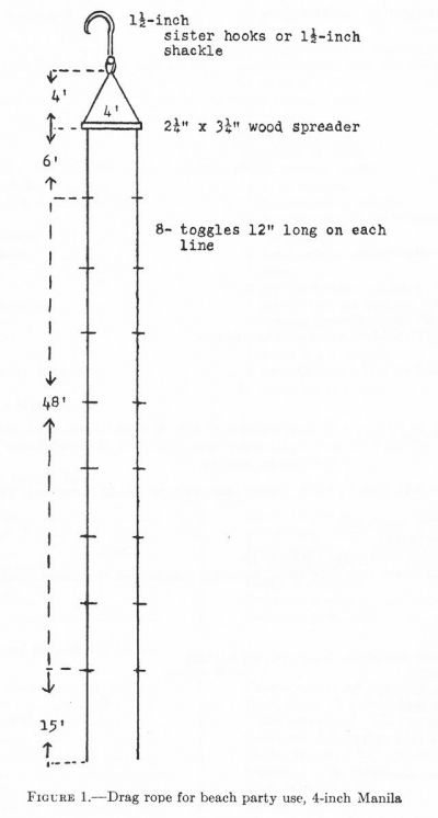
Chapter VIII. Communications
(This chapter is a reprint of "Joint U.S. Air-Amphibious Communication Instructions"
as approved by the Joint Communication Board)
| Section | 1. | Definitions and assumptions | 29 |
| Section | 2. | Planning | 31 |
| Section | 3. | Training | 33 |
| Section | 4. | Preembarkation phase | 33 |
| Section | 5. | Embarkation | 34 |
| Section | 6. | Movement to theater of operations | 35 |
| Section | 7. | Approach | 36 |
| Section | 8. | Debarkation and assault | 37 |
| Section | 9. | Consolidation | 62 |
| Section | 10. | Check list | 62 |
| Section | 11. | Basic communication plan | 66 |
| Appendix | A. | Joint shore party communication team | 70 |
| Appendix | B. | Air support | 71 |
| Appendix | C. | Air defense | 74 |
Section 1. Definitions and Assumptions
- Definitions.--
-
Air group.--
Air liaison party.--Air support parties attached to landing teams, combat teams, or higher headquarters, to link air support with ground requirements.
AK.--Cargo vessel.
AKA.--Cargo vessel capable of combat unit loading.
AP.--Transport.
APA.--Combat unit loaded transport for a landing team.
Artillery spotting plane.--Aircraft to observe for ground artillery.
Beach.--Shore line of a landing area assigned a landing team.
Beachhead.--A position organized in depth with a view to offensive or defensive operations which protects the beach initially from light artillery fire; eventually, from medium artillery fire.
Beachmaster.--Naval officer responsible for beaching and unloading boats.
Boat flotilla.--Boat groups for a transport division.
Boat group.--Boats required for one landing team.
Boat wave.--Boat formation for landing simultaneously on a given beach.
Cargo vessel.--AK.
Carrier.--CV.
Combat loaded.--Embarkation to facilitate immediate assault on a hostile shore.
Combat team.--Reinforced infantry regiment.
Commander landing force.--Commander of ground forces committed in an assault on a hostile shore.
Commander naval force.--Commander of naval force in an assault on a hostile shore; normally, the Task Force Commander.
Commander air force.--Commander of air group or force assigned to support an assault on a hostile shore.
--29--
Communication officer.--Army or Marine line officer in regiments and battalions assigned signal communication specialty; or, Navy officer in charge of all visual and radio communications for a ship, unit, task group or force.
Control vessel.--Vessel to guide and assist boat traffic.
Demonstration group.--Vessels assigned the task of making demonstration outside the designated landing area.
Direct support aircraft.--Aircraft (carrier or land based) of the air group designated in close support of ground forces.
Fire support group.--Combatant vessels designated to support landing and subsequent operations by gunfire missions.
Guide flags.--Visual markers to aid navigation.
Guide plane.--Aircraft designated to assist in navigation of boat groups.
Gunnery observation spotting plane.--Aircraft to observe and direct naval gunfire.
Headquarters ship.--Vessel (preferably noncombatant) from which task, naval, landing, and air commanders exercise control in landing operations.
Joint shore party communications team.--Army/Marine and Navy detachments to establish communications seaward, landward, and laterally in support of a landing.
Landing area.--Air, ground, and sea areas involved in an amphibious operation.
Landing force.--Military organization to execute landing operations from the transports of a task force.
Landing team.--Reinforced infantry battalion to assault an hostile shore.
Line of departure.--Coordinating line at sea suitably marked to assist the various waves to land on designated beaches at the proper time.
Military.--Army and/or Marine.
Mine group.--Vessels designated for mine sweeping and mine laying.
Naval force.--Naval organization for landing operations.
Naval support area.--Sea area assigned combatant naval support vessels.
Opposite numbers.--Military and naval officers of similar command and staff assignment.
Reconnaissance group.--Vessels designated to reconnoiter a landing area preliminary to the landing.
Screening group.--Vessels designated to protect the naval force.
Salvage group.--Vessels designated to rescue personnel, equipment and matériel.
Shore fire control party.--Naval and artillery liaison party with signal communication personnel, supporting a landing team.
Shore party.--Special military detachment to organize logistic operations on the beach.
Signal communications.--Comprise all methods and means employed to transmit messages and telephone conversations. Messages include all written official messages, reports and instructions.
Signal officer.--Army/Marine staff officer of large units (division, higher or equivalent) specializing in signal communications; Navy officer in charge of visual communications for a ship or flag officers staff.
SOP.--Standing operating procedure. (Naval use defines SOP as "Senior Officer Present".)
SOI.--Signal operation instructions.
Task force.--Joint overseas expedition for operation against an hostile shore.
Task group.--Subdivision of a task force.
Transport vessel.--AP.
Transport area.--Water area assigned for debarking troops from the transports.
Transport division.--Vessels designated to transport one combat team.
- Assumptions.--
2. Basis of analysis: Reinforced infantry division supported by air and sea forces.
3. It is imperative, immediately upon establishment of the beachhead, that the landing force or an advanced naval base unit establish external communications. Safety of the naval vessels may require a sudden departure from the area. It is necessary to prescribe this responsibility as early as possible in the planning phase.
b. Organization.--
1. Landing teams are reinforced infantry battalions.
2. Combat teams are reinforced infantry regiments.
c. Time.--
1. Concentration of forces should be effected within 72 hours of embarkation; or, by infiltration into dispersed areas.
2. Approach and assault should be effected under cover of darkness with due consideration for tide.
d. Space.--
1. Concentration should be concluded within 15 miles of the embarkation points.
2. A transport area will be from 6,000 to 18,000 yards offshore.
3. The line of departure is from 3,000 to 6,000 yards offshore.
4. Normal ground objectives: Landing team, 1 square mile; combat team, 2 square miles; division, 6 square miles; with landing areas for one corps approximating 15 square miles; and army, 30 square miles.
5. Boats: For centralized control, boats are limited to 200 yards interval by 100 yards depth; boat group, 1 by 5 miles; boat flotilla, 3 by 30 miles; a division afloat, 6 by 75 miles; task group or force afloat, 30 by 100 miles.
e. Operations.--
1. Ship-to-shore, shore-to-shore and air-borne-sea-borne are fundamentally similar.
2. Assault is on a broad front with the reinforced infantry division as the task group, minimum in assault and maximum in reserve, the latter to be committed dependent upon maneuver room.
3. Phases:
a. Planning phase during which plans and training culminate with a rehearsal and review of plans.
b. Training.
c. Preembarkation during which preparations are completed for embarkation.
d. Embarkation phase wherein the landing force is embarked preparatory to sailing.
e. Voyage phase of sea convoy to a theatre of operation culminating in the approach.
The approach is that part of the voyage wherein the naval force divides into task groups to proceed to respective transport areas preparatory to debarkation.
f. Landing operations phase is the assault against an hostile shore. This is subdivided into the following assault phases:
Assault landing teams en route to beach.
Establishment of landing teams ashore.
Establishment of combat teams ashore.
Establishment of the division headquarters ashore.
g. Consolidation phase is the transition from the amphibious operations phase to normal operations.
Section 2. Planning
- Agencies and Responsibilities.--
- The Combined Communications Board is the supporting agency of the Combined Chiefs of Staff on communication matters; and is responsible for coordinating methods, procedures, operations, equipment and all communication matters of combined application.
- The Joint Communications Board is the supporting agency of the Joint U.S. Chiefs of Staff on communication matters; and, is responsible for coordinating methods, procedures, operations, equipment and all communication matters of joint U.S. application.
- The Army Communications Board is the supporting agency of the U.S. Army Chief of Staff on communication matters; and, is responsible for coordinating communication methods, procedures, operations, equipment and all communication matters applicable to the U.S. Army.
- The Director of Naval Communications is the supporting agency of the Chief of Naval Operations on communication matters; and, is responsible for coordinating all communication matters applicable to the U.S. Navy.
- Joint Air-Amphibious Communications Planning board is the supporting agency of the Joint U.S. Chiefs of Staff to specialize on strategic doctrine and tactical plans for air-amphibious operations; and, is responsible for accumulating data on air-amphibious operations for constant liaison with strategic operational planning; and, for preparation to assist specific task force planning.
- The Joint Air-Amphibious Communications Planning Staff is a special joint staff to assist a theatre commander with plans for air-amphibious operations or exercises; and, is responsible to a theatre commander to anticipate air-amphibious possibilities and prepare the plans therefor.
- The Joint Air-Amphibious Communications Plans Conference is a special conference of communication and signal officers to prepare a plan for a specific air-amphibious operation; and, is responsible for planning a specific operation.
--31--
- Scope.--
- The planning phase is one of the most important phases of the entire operation. Omissions and oversights during this period cannot be remedied later. Detailed study is essential.
- Joint planning conference.--
- Immediately upon receipt of information that a landing exercise or operation is to be conducted the amphibious force communications officer and the senior signal officer will meet and jointly draft an outline plan of communications based upon tactical plans. Types and quantities of special equipment needed will be determined and steps taken to procure such equipment immediately.
- When subordinate naval and military communications officers are given sufficient information, each will confer with his opposite number and prepare orders and annexes.
- As far as practicable, all joint appendices to the communications annex (such as frequency tables, cryptographic instructions, call signs) will be prepared from the same stencil in sufficient quantity to supply naval and military components.
- When orders have been completed, and immediately before departure for exercise or operation, all military and naval communication officers to include battalion communication officers and individual ship communications officers, will confer to jointly study the plans and straighten out any questionable items. A similar conference will be held immediately after exercises to determine causes of any failures and corrective action to be taken.
- In making arrangements for final conferences prior to an actual operation, particular attention will be paid to provisions for preservation of secrecy. Efforts will be made to hold these conferences after departure from base but prior to departure for the theater of operations. Communications officers having attended these conferences must be especially careful during time spent ashore. All communications plans, orders, authenticators, SOI's and other pertinent communication information should be distributed as early as practicable. The purpose of the communication conference possible eventualities and alternate plans will be discussed.
- Military and naval opposites shall maintain close liaison and confer as necessary to insure smooth coordination of effort.
- Time factors for air-amphibious operations relative to normal operations demand emphasis on security.
Section 3. Training
- Preliminary training.--
- Preliminary training is defined as that fundamental air-amphibious training that may be executed by the normal training agencies of the military and naval forces. This will include inculcation of officers and specialists with the doctrines of air-amphibious organizations, operations, and signal communication; and, the inclusion in mobilization training programs of those phases of an air-amphibious operation applicable to intraservice instruction. The latter includes organization of personnel, equipment, and matériel for combat loading; and, instruction on assembly of personnel and dumping of supplies; technique of embarking and debarking from ships; and, general description of the operation.
- Instruction for officers, noncommissioned officers, petty officers, and other communication personnel on the signal communication systems applicable to air-amphibious operation.
- Advance training.--
- Advance training is defined as special training in an air-amphibious training area prior to participation in an air-amphibious operation.
- Initial phase of advanced training will determine the combat efficiency of a given unit; and, complete training to qualify the given unit with the standards of preliminary training.
- The second phase of advanced training will include specialist, special detachment, and unit training to perfect the technique and tactics of landing teams. Night operations will be emphasized. This phase will terminate with tactical tests and signal communication exercises to determine qualifications of landing teams to effect a successful landing.
- Special operations training.--
- Special operations training is defined as that training to condition combat teams and divisions for a specific air-amphibious operation.
- Initial phase will include a test of combat teams in the technique of a landing; the execution of command post exercises to train staffs and special detachments; and, instruction in plans, orders, and executions for a specific operation.
- The second phase will condition an infantry division to concentrate, embark, debark, and assault a hostile shore.
- The third phase will consist of a maneuver to determine the combat efficiency of a given division for an air-amphibious operation.
- The final phase will effect a rehearsal for the special operation under conditions as similar to those in the projected operation as is practicable. This training phase should conclude with a critique of communications plans.
- Review of operations plan.--
- The review of operations plan is defined as a reconsideration of a prepared plan of operation based upon the combat rehearsal.
- In addition to revision of the operational plan, it is essential to expedite special training, to correct faults determined in the rehearsal with specialist, special detachment, or tactical training.
- Training programs, schedules, and observations should be filed for study during the voyage; and, copies forwarded to planning agencies for their information and study.
- Time factors for air-amphibious operations relative to normal operations demand emphasis on security.
Section 4. Preembarkation Phase
- The preembarkation phase is the 72- to 90-hour period immediately preceding the actual embarkation of the landing force, during which final arrangements must be completed.
- Advance parties.--Insofar as practicable, communication and signal officers shall embark three days in advance of the landing force. These officers shall bring sufficient communication personnel to establish advance message centers. The respective military and naval representatives will establish smoothly functioning unit and joint communication agencies on board ship in advance of the arrival of the landing force.
- Ship and staff communication officers will make arrangements for the reception of the foregoing officers and men; and, for the provision of adequate space for unit message centers. This space should be located as near the ship's communication office as is practicable.
--33--
- Information regarding communications to be exchanged.--
- Naval communication officers will furnish landing force communication officers with adequate copies for distribution of the following:
- Suitable diagrams showing office and communication spaces.
- Roster of naval officers aboard, showing their official capacities.
- Landing force communication officers will furnish the Navy communication office with:
- List of Army officers aboard and their official capacities.
- Call signs of embarked units, cryptographic systems held, and other information pertinent to communications.
- Naval communication officers will furnish landing force communication officers with adequate copies for distribution of the following:
- Military communication personnel for ships carrying a headquarters comparable to a division will be provided from units not participating in the landing phase; and, will remain on board the ship as long as there exists necessity for communicating with the landing force. They will be landed when released by the senior naval communication officer on the ship.
- Representatives of the senior military and naval commanders will, in conference with their respective intelligence sections, determine what special communications will be required for last-minute reconnaissance reports from patrols, agents and aircraft; and, will arrange for such communications.
- In the period prior to embarkation all ship communication officers and unit signal and communication officers shall make a complete test of all communication equipment, including batteries and spare parts. Dial settings of transmitters and receivers for all frequencies on which each equipment may operate shall be determined and recorded.
- Headquarters ship communication personnel.--Well in advance of any projected landing exercise or operation the communication personnel of the headquarters ship shall be embarked and trained in their individual and team duties.
Section 5. Embarkation
- Loading of equipment.--Embarking signal and communication officers will arrange with the transport quartermasters and the transport communication officers to insure that communication equipment is loaded so as to be readily accessible; and, in such a manner as to provide for the correct unloading sequence. Equipment which is to be employed in the assault phase should be stowed in message centers, auxiliary radio rooms, radio spare part stowage, or other spaces under the control of the ship's communication officer so that it can be serviced readily; and, be available for use. spare parts and accessories for communication equipment to be landed shall be stowed with their associated equipment and landed intact.
- All officers responsible for communication equipment shall insure that a liberal supply of batteries and spare parts is on hand and accessible on board ship. Batteries must be stowed in cool, dry spaces.
- Communication equipment to be used subsequent to the assault phase (such as base communication equipment) should be inventoried, tested, and carefully repacked before loading.
- The loading plan for communication personnel and equipment not to be landed with assault units (including advance base and 90-day replenishment equipment) must be coordinated with the transport quartermasters to provide for distribution between ships to avoid excessive loss in case of sinkings. Furthermore, priority of unloading should be such that equipment to establish advance base communications will be unloaded as soon as the assault permits.
- Pyrotechnic supplies of the landing force will be stowed in the ship's pyrotechnic locker or locker with similar specifications.
- It must be borne in mind that this period may be the last opportunity for distribution of plans, maps, and other documents. Navy guard mail service is available for this purpose and embarked units should utilize it to the utmost.
--34--
- The ship's communication officer is responsible for the receipt of all messages addressed to embarked units and for the expeditious delivery of these messages to the unit message centers.
- Message centers will begin full operation at the hour designated for the start of embarkation and operate thereafter on a 24-hour basis.
- Use of telephones.--During the embarkation period ships, which are along side of docks, will have connections ordinarily with the commercial telephone system. The use of such telephone service must be supervised from the view point of security for classified information.
- It must be borne in mind by all landing force personnel that administrative matters must be completed prior to sailing of the convoy. Visual signalling during daylight hours and limited dispatch boat service will be the only means of handling traffic between elements of the landing force during the voyage. Tactical traffic pertaining to the control and movement of the convoy will have priority on all visual channels and it may be impossible to handle any other class.
- Embarked units will detail messengers to the ship's communication office, the radio room, and the signal bridge as may be necessary for the expeditious handling of messages for the landing force.
Section 6. Movement to Theater of Operations
- The Navy will provide all exterior and intership communications enroute to the theater of operations. Naval cryptographic channels will normally be used. All traffic originated by the landing force is subject to approval for release by the naval communication origination. In many cases it will be necessary to prohibit the release of this traffic in order to keep communication channels open for tactical traffic essential to convoy maneuvering.
- Visual communications.--Communications will normally be restricted to daylight visual means. Even then, the use of searchlights may be prohibited in areas where enemy air search is probable.
- Use of landing force equipment at sea prohibited.--No landing force radio equipment may be operated at sea enroute to the theater of operations without approval of the naval force commander. This includes all electrical apparatus with radiating characteristics.
- Inspection of equipment.--Accessible communication equipment shall be kept in efficient operating condition at all times, ready for immediate use. Such equipment, both ship and unit, shall be inspected frequently; and, serviced as necessary. This inspection shall include batteries and spare parts. Radio equipment shall not be turned on.
- Dispatch boats for the delivery of maps, photographs, operation orders and similar matter between elements of the convoy may be provided during long voyages. This service will be dependent on the availability of suitable ships and the tactical situation.
- Radio silence shall be maintained during the voyage unless this condition is officially modified by the naval force commander. Radio silence prohibits all transmissions, of whatever nature, including tuning.
- During the passage to the theater of operations communications personnel must utilize all available time for intensive training and study of orders. Such training will include the following:
- Study or orders and instructions by officers and enlisted men.
- Practice in handling effective cryptographic systems.
- Communication drills in which prepared drill messages will be completely enciphered, deciphered, recorded and delivered. Accuracy and speed are the objectives.
- Training messengers in delivery of traffic to all parts of the ship under darkened ship conditions.
- Training of messengers in the recognition and identification of staff officers.
--35--
- Duty assignment cards.--Communication and signal officers will prepare a duty assignment card for each member of their respective communication units participating in the ship-to-shore assault. In general such details as follow are shown thereon:
Name and grade.......................................................
Duty to which assigned.............................................
Your NCO is.............................................................
Your officer is..........................................................
Your debarking station is.........................................
Your abandon ship station is....................................
Your fire station is...................................................
Your general quarters station is...............................
You will be landing on..............................................beach
Your are responsible for the following communication equipment:
..................................................................................................
..................................................................................................
..................................................................................................
Section 7. Approach
- General.--At some stage during the voyage it will become necessary for the naval force to divide into several task groups, for the approach to the various transport areas opposite their respective beaches. At this time the communication plan must provide necessary links between the several task groups and the force commander; and, at the same time, provide the task group commanders with the necessary communications to exercise control for the assault.
- Preparation of equipment for landing.--During this phase communication equipment to be landed must be broken out and prepared in every respect for landing. Particular attention should be given to the condition of batteries and towaterproofing provisions for the equipment not designed for this employment.
- Tuning of portable radio equipment.--Portable radio equipment shall be checked carefully to see that dials are set properly for the frequency on which these sets are to be operated; and, for those so provided, tuning dials shall be locked. Nonradiating receivers should be tested for operation. Until the restrictions imposed by radio silence permit the tuning and netting of the equipment, the difficulties arising from security restrictions cannot be wholly overcome, but will have been minimized by:
- Constant netting drill and practice to including training at night.
- Careful netting before embarkation; recording of exact dial readings.
- Use of frequency meters and built-in crystal calibrators.
- Careful instruction in the use of calibration curves and charts.
- All units must synchronize watches with ship's time immediately prior to debarkation. Provisions will be made for daily time checks.
- During the approach, communication and signal officers must reexamine the details of the communication plans for debarkation and assault in the light of the then existing conditions. Casualties to personnel and equipment and/or late intelligence undoubtedly will require a readjustment of personnel assignments, boat assignment tables and allocation of equipment. Alternate plans must likewise be revised.
- Forward and rear echelons.--The communication personnel will be divided into two echelons. The first goes ashore with the forward echelon of the unit headquarters to establish the initial command post on land. The rear echelon aboard ship remains in operation until ordered ashore.
- It is the responsibility of the signal or communication officer to insure that debarkation tables provide for the dispersal of personnel and equipment of his unit between two boats.
--36--
Section 8. Debarkation and Assault
- The debarkation and assault phase may be logically subdivided into four phases.
- Phase I.--
- This phase covers the following evolutions: Debarkation of troops, loading of boats, organization of boat waves, movement by waves to rendezvous area, movement of boat group to line of departure and the final movement to the beach.
- During this phase radio silence is normal and communications are restricted to voice and visual means (arm and flag signals during daylight; carefully screened lights, in darkness). However, military tactical radio nets are manned in readiness for instant use should the element of surprise be lost; or, emergency arise. Continuous listening watches are maintained.
- The communication plan will enumerate the specific conditions under which radio silence may be broken during the ship-to-shore movement. No dogmatic determination of the specific time when radio silence may be broken can be set forth.
- Loading of equipment in boats.--Signal equipment, such as radio sets and other fragile items, should be loaded in the boat at the rail; if practicable; otherwise, it will be lowered into boats by means of ropes and guide lines. No unit will plan to land signal equipment too bulky to be justified by the tactical situation. Plans will be made to delay the debarkation of heavy pieces until they can be taken ashore with the proper degree of safety for the equipment.
- Boat assignments.--From the standpoint of efficient communications, it is highly desirable that certain commanders and special communication teams be embarked together in certain boats as follows:
- The boat group commander with the landing team commander.
- The assistant boat group commander with the landing team executive officer.
- The shore fire-control party, in a boat adjacent to that of the landing team commander, in order to be able to call for direct fire while the landing force is water-borne.
- The air liaison party in a boat adjacent to that of the landing team commander if direct air support is provided.
- The shore party commander and the beachmaster should be embarked in an adjacent boat of the same wave.
- Special radio nets.--
- When conditions require the appointment of a boat flotilla commander, a special radio net is provided which will include the flotilla commander, each of his boat group commanders and the transport division commanders. This net is omitted when the flotilla organization is not used.
- The control vessel must be prepared to operate in the boat group commander's circuit, commanders control vessels circuit and with the fire support group supporting the beach.
- Commander of the transport division will listen in on the control vessel circuit. He may put a transmitter on this circuit if he has one available. It is probable that the commander naval force will also listen on this circuit during the initial stages of the ship-to-shore movement. If a guide plane be employed, the boat group commanders and the combat team commanders will be vitally interested in the information and the directions which will come from the guide plane. It is, therefore, essential that the boat group commander operate a set in the combat team net. It is necessary that the frequency for this net be prescribed by the highest echelon.
- List of diagrams.--
FIGURE 1.--Organization chart.
FIGURE 2.--Boat group control circuit.
FIGURE 3.--Combat team net.
FIGURE 4.--Direct support aircraft circuit.
FIGURE 5.--Transport division command circuit.
FIGURE 6.--Boat control circuits.
--37--
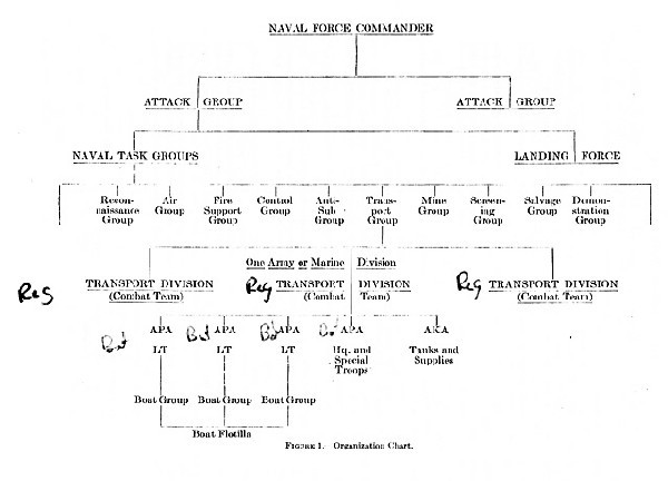
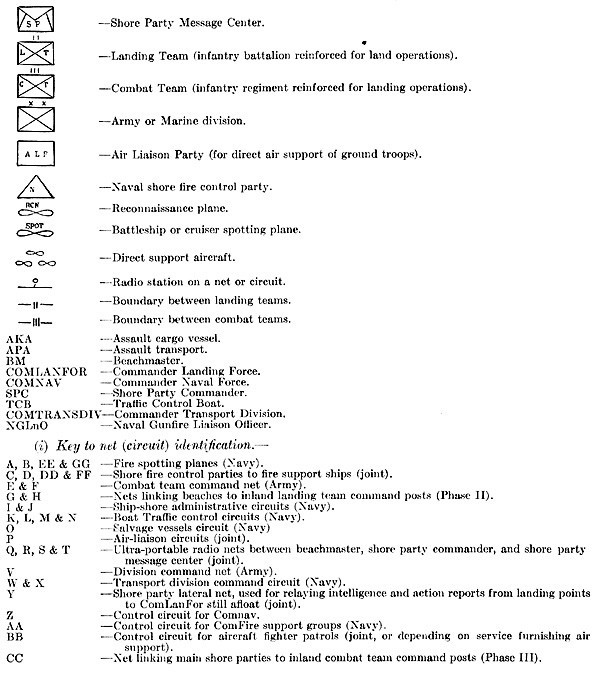
Phase I and II--Boat Group Control Circuit
Radio--TBY or SCR-511--Navy Circuit
NOTE.--This figure does not indicate the correct position of the boat relative to the waves, but merely indicates the communication net.
--39--
Phase I and II--Boat Group Control Circuit
Radio--TBY or SCR-511--Navy Circuit
NOTE.--This figure does not indicate the correct position of the boat relative to the waves, but merely indicates the communication net.
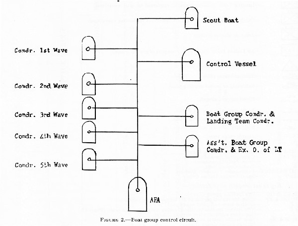
The boat waves are controlled in their movement by a control vessel, normally a destroyer, which times and directs the movement of the boat waves from the line of departure.
The scout boat, if used, usually a support boat or speedy personnel boat equipped with motor silencers, acts as a beacon or guide to boat waves approaching the beach.
The boat waves depart from the line of departure upon direction by the control vessel. The second wave commander is normally beachmaster.
The third wave carries the shore fire control party which aids in the spotting for naval gunfire by giving essential information such as location, and strength of enemy gun emplacements and batteries. The third wave also carries the air liaison party when attached to a landing team.
The third or fourth wave carries the joint shore party communication team which later establishes shore communications.
The transport must remain in communication with all the units shown in figure 1 in order that it can be prepared to supervise, receive prompt report on the nature of the landings, to alter boat loading priorities, cease unloading or withdraw, if necessary.
The ship may lose contact with the boat group passing out of radio range, in which event the control vessel may act as a relay.
--40--
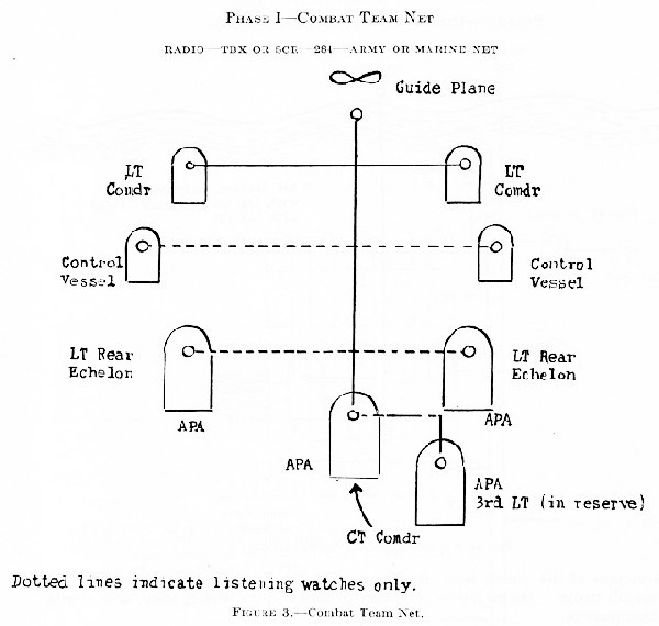
Each transport carries a battalion landing team. This circuit (net) is between the combat team commander on the Trans Div flagship and the landing team commanders for tactical control. One landing team is normally kept in reserve either in the transport or in boats. Each landing team communication platoon is divided into two echelons, a forward and a rear, the latter maintaining a listening watch on this net. The several landing teams operate on different beaches. A guide plane may be on this circuit in order to assist the boat waves to the beaches. Control vessels should listen for information.
--41--
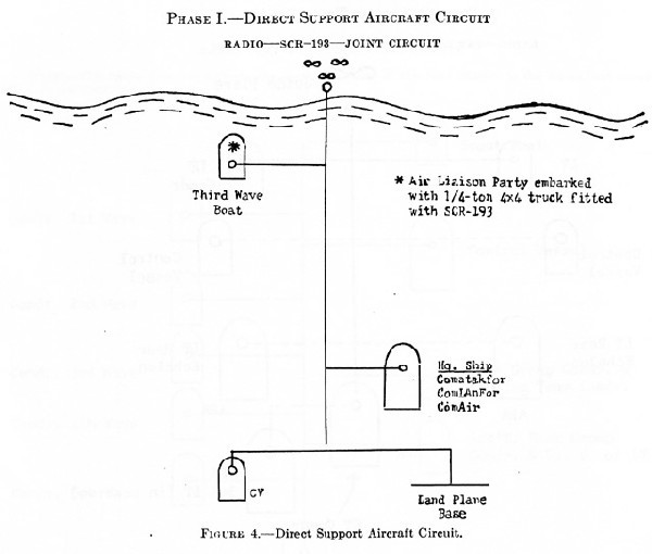
The purpose of this circuit is to afford communication between the supporting aircraft and the assault troops. The air liaison party may go ashore with a landing team; or later with the CT headquarters.
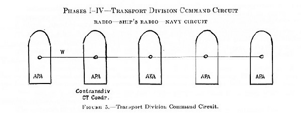
This circuit gives the transport division commander control of the ships under his command. In practice two paralleled circuits may be employed, one a voice circuit for emergency use, the second a key circuit for other purposes. Visual signalling is used whenever possible.
--42--
Phase I--Boat Control Circuits
Radio--SCR-511 or TBY--Navy Circuit
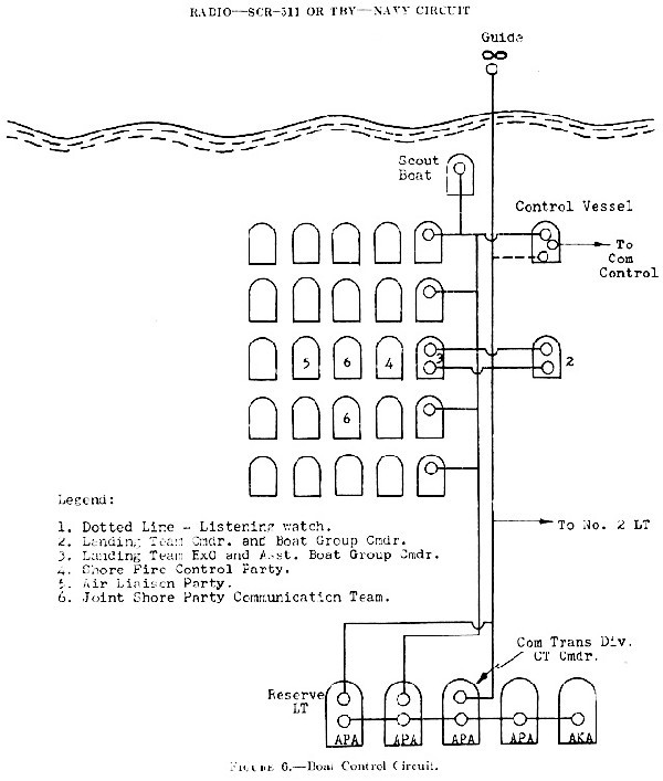
- Phase II--Introductory statement.--
- The second phase of the landing attack is the period when landing teams are ashore and combat team commanders are still afloat.
- List of diagrams:
FIGURE 7.--Traffic control and salvage vessel circuit.
FIGURE 8.--Combat team command net.
FIGURE 9.--Direct support aircraft circuit.
FIGURE 10.--Air spot and shore fire control nets.
FIGURE 11.--Ship-to-shore administrative circuit.
FIGURE 12.--Shore party lateral net.
FIGURE 13.--Local shore party circuit.
FIGURE 14.--Battalion shore party net.
FIGURE 15.--Naval task force commander's circuit.
FIGURE 16.--Division command net.
FIGURE 17.--Fire support circuit.
FIGURE 18.--Combat air patrol circuit.
FIGURE 19.--Consolidation. - During this phase radio, messenger, visual and sound systems are normal. The use of wire during the early phases of the assault will be dependent on several factors which must be carefully weighed for each particular situation. Track laying vehicles and wheeled transportation preclude the laying and maintenance of wire lines on the ground, in the vicinity of the beach and for a considerable distance inland. Overhead wire lines, when feasible at all, require time and labor, which might better be devoted to other requirements until congestion and traffic abate. Should it be determined that the bulk and weight of wire equipment do not warrant the use of boat spaces in the leading wave, detailed arrangements must be made for the subsequent landing of this type of equipment. Landing teams will plan and make provision for the use of wire as early as practicable after leaving the vicinity of the beach.
Phase II--Traffic Control and Salvage Vessel CircuitRadio--TBY or SCR-511 (Navy Circuit)--Navy Circuit
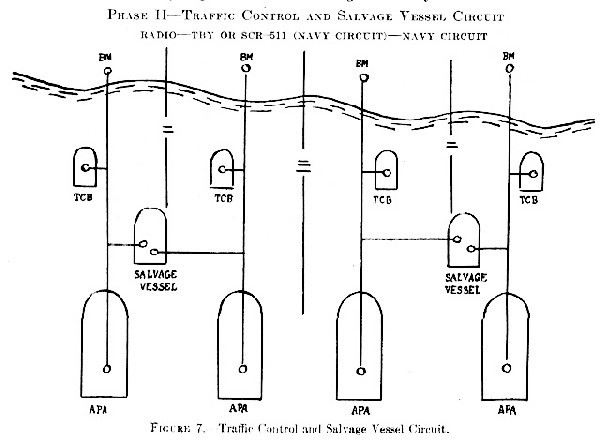
The beachmasters are ashore and in communication with the traffic control boats, salvage vessels and transports to regulate and direct the movement of boats to and from the beach. Because of short range of equipment and direct communication between beach and transport may be impossible. In this case, the traffic may be relayed by salvage vessel or sent on the ship-shore circuit.
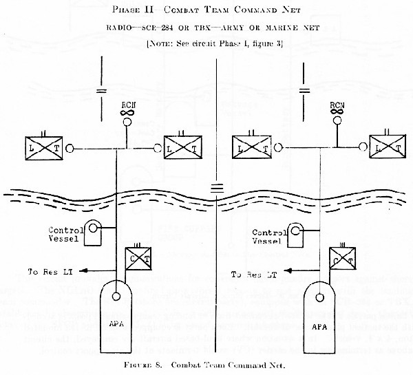
The CT commander aboard the transport is in communication with the LT's which are proceeding inland. A reconnaissance plane assigned to the CT will operate in this net. The rear echelon of the landing teams may, or may not, be operating their radio equipment at this time.
--45--
Phase II--Direct Support Aircraft Circuit
Radio--SCR-193--Joint Circuit
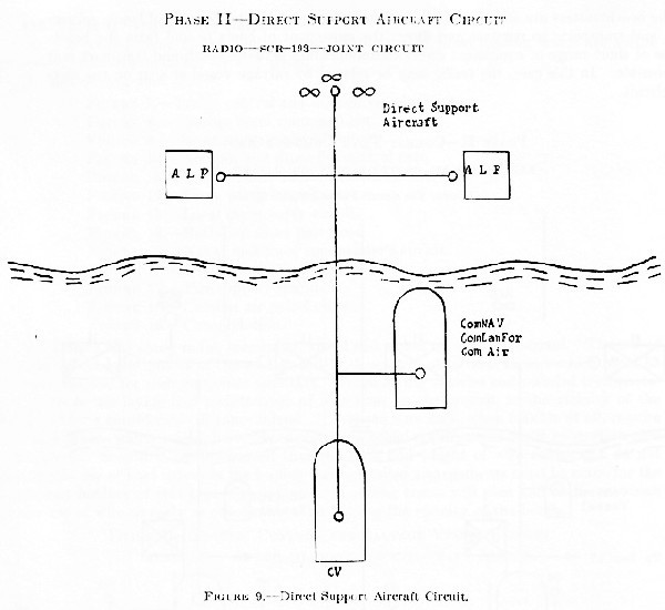
Air liaison parties will be located at combat team of landing team command posts in accordance with the tactical plan for use of aircraft. Each party is equipped with SCR-193 mounted in a 1/4-ton, 4x4 vehicle. In a situation where land-based aircraft are employed, the circuit shown above as terminating in the carrier (CV) would terminate at the air-support control.
--46--
Phase II--Air Spot and Shore Fire Control Nets
Radio--SCR-284 or TBX--Joint Net
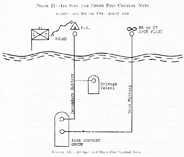
This circuit provides communications for control of naval gunfire support against shore targets. The NGLnO (naval gunfire liaison officer) reports to and remains with the landing team commander. The SFCP (shore fire control party), equipped with an SCR-284 or TBX, establishes the observation post and is in direct radio contact with the fire support ship. Contact between the SFCP and the NGLnO is by sound-powered telephone.
--47--
Phase II--Ship to Shore Administrative Circuit
Radio--SCR-284 or TBX--Joint Circuit
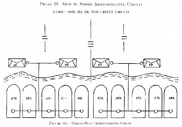
This net provides communication between the transport division and the shore parties for the purpose of controlling the flow of supplies to the beach, the evacuation of personnel, and other administrative matters. Visual and messenger boat communication is used to the maximum extent.
--48--
Phase II--Shore Party Lateral Net
Radio--SCR-284 or TBX--Army or Marine Circuit
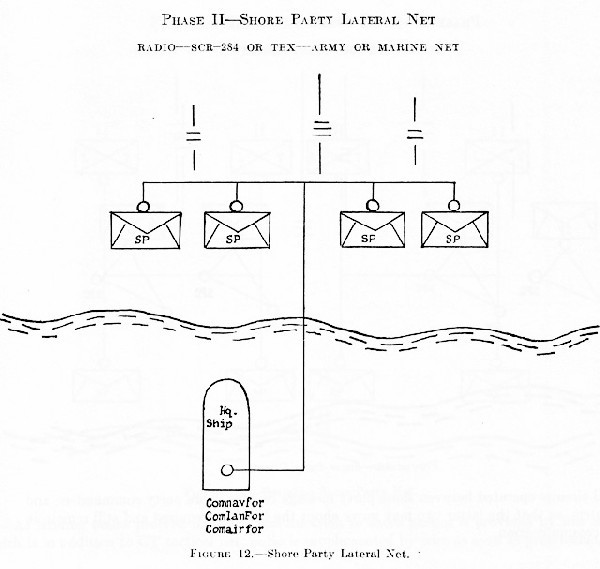
This net provides the naval, air, and landing force commanders with a flow of tactical information as to conditions on the beaches. Shore radio circuits are paralleled by wire as soon as possible.
--49--
Phase II--Local Shore Party Circuit
Radio--SCR-536--Joint Circuit
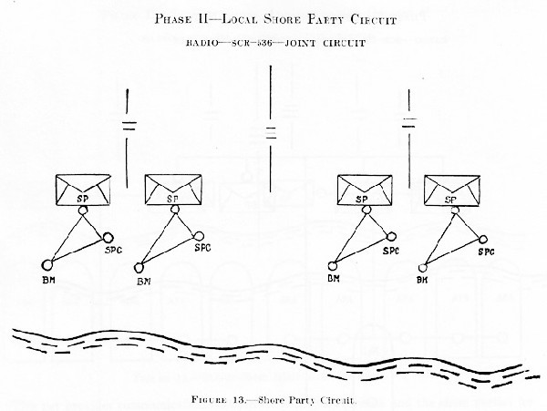
Local circuits operated between shore party message centers, shore party commanders, and beachmaster, so that the latter two may move about the beach as required and still remain in constant communication.
--50--
Phase II--Battalion Shore Party Net
Radio--SCR-284 or TBX--Army or Marine Net
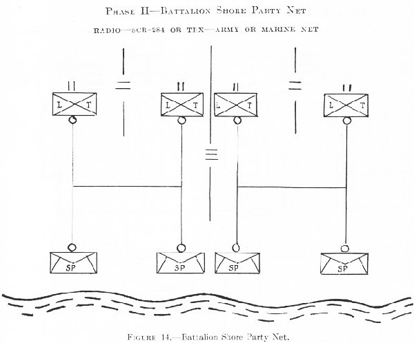
As landing teams proceed inland, communication to shore parties is provided by this net, which is in addition to CT tactical net; radio is supplemented by wire as soon as practicable.
--51--
Phased II--Naval Task Force Commander's Circuit
radio--Ship's radio--Navy Circuit
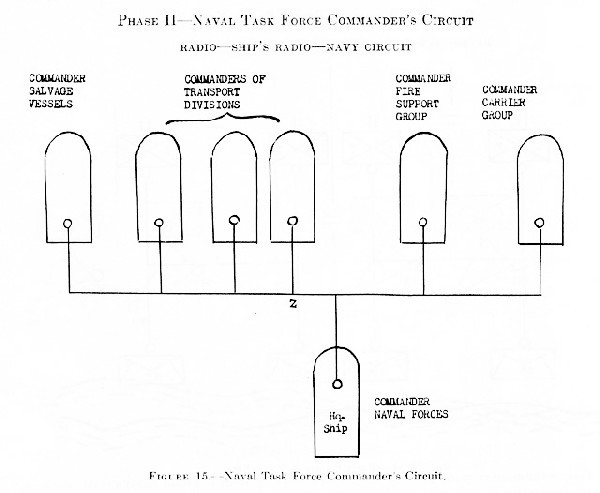
This is a command circuit and provides the commander of the naval force with communications to his subordinate commanders. The number of subordinate commanders on this circuit will vary with the size and composition of the naval force participating.
--52--
Phase II--Division Command Net
Radio (Ship's While Afloat, and Army or Marine on Shore) Army or Marine Net
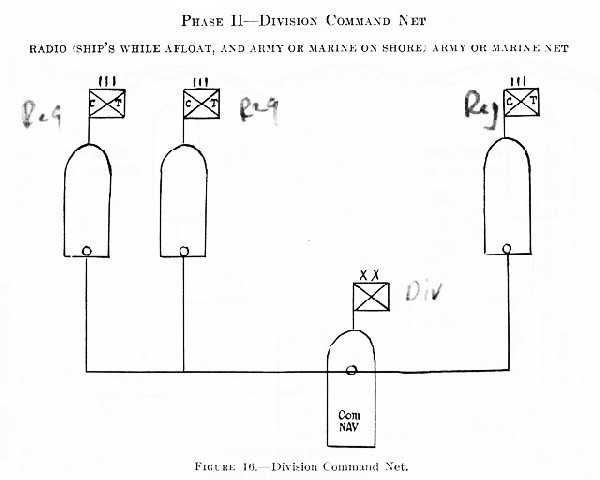
The CT commanders are usually aboard the same ships as the commanders of the transport divisions.
--53--
Phase II--Fire Support Circuit
Radio--Ship's--Navy Circuit
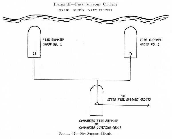
This circuit permits the commander of the fire support group to control the several elements of the fire support group.
Phase II--Combat Air Patrol Circuit
Radio--Ship and Aircraft radio--Air Circuit
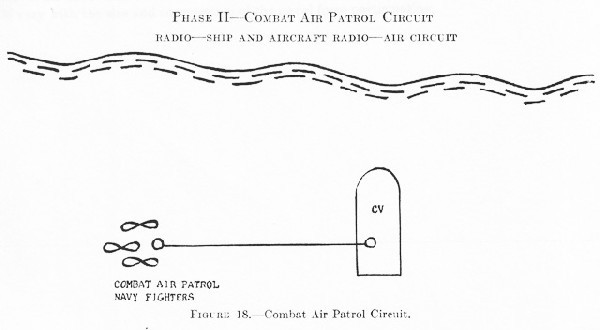
The carrier uses this circuit to control its planes on combat air patrol.
--54--
Amphibious radio Channels
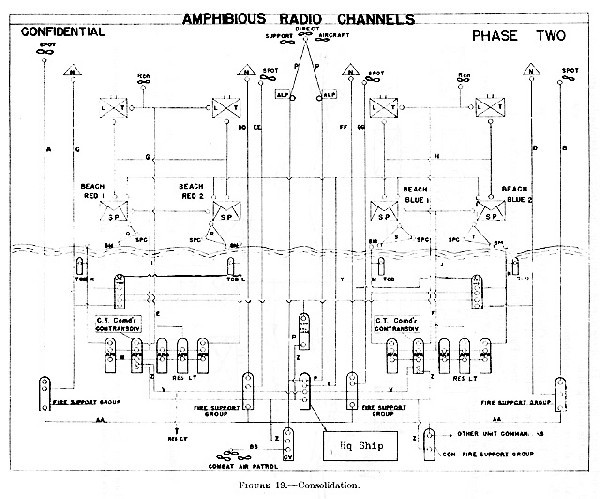
--55--
- Phase III.--
- Introductory statement.--In this phase of the landing attack the several combat team headquarters have been established ashore. The Landing Teams have proceeded farther inland. The shore parties continue in the operation of unloading stores and supplies form the landing boats.
- List of diagrams.--
FIGURE 20.--Division Command Net.
FIGURE 21.--Combat Team Command Net.
FIGURE 22.--Shore Party to Combat Team Headquarters Net.
FIGURE 23.--Consolidation.
Phase III--Division Command Net
Radio--Ship's Radio, SCR-284 or TBX--Army or Marine Net
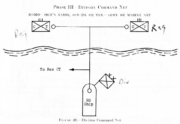
This net is the Army or Marine division command net shown after the combat team headquarters have landed, but division headquarters is still afloat.
--56--
Phase III--Combat Team Command Net
Radio--SCR-284--Army or Marine Net
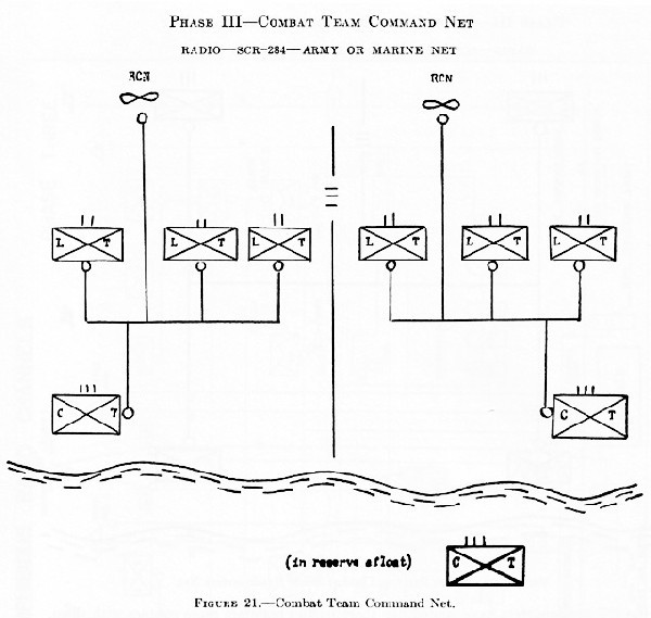
This is the same circuit as Phase II, figure 8, except that the combat team commanders and the reserve landing teams are now ashore.
--57--
Phase III--Shore Party to Combat Team Hqs. Net
Radio--SCR-284 or TBX--Army or Marine Net
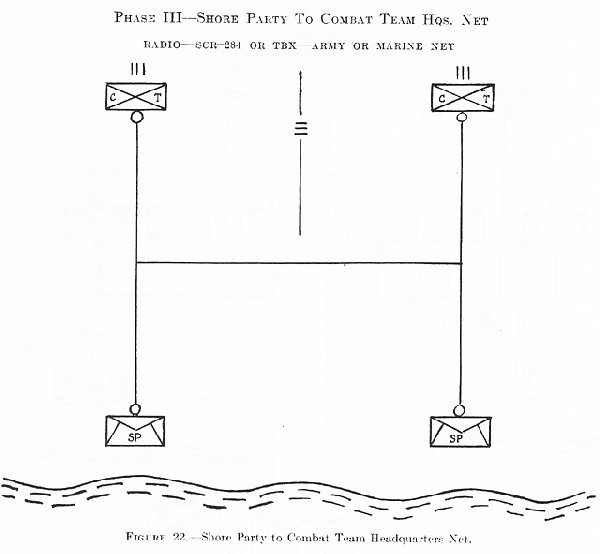
After CT headquarters have landed, the shore parties maintain radio contact with them.
--58--
Amphibious Radio Channels
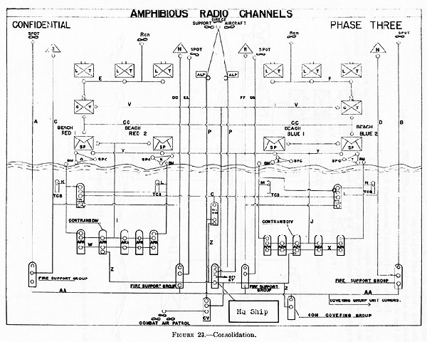
--59--
- Phase IV--Introductory statement.--
- In the fourth and final phase of the landing attack, the commander of the landing force has established headquarters ashore. The shore party is in visual communication with the unloading transports and cargo ships.
Naval air and gunfire support continue as long as they are needed.
- List of diagrams:
FIGURE 24.--Division Commander's Net.
FIGURE 25.--Consolidation. - In this phase all signal communications will approach intraservice normal systems. Joint shore party systems (wire, radio, messenger, visual and sound) will have been installed and in operation; and, modifications will be initiated in anticipation of the consolidation.
- In the fourth and final phase of the landing attack, the commander of the landing force has established headquarters ashore. The shore party is in visual communication with the unloading transports and cargo ships.
Phase IV--Division Commander's Net
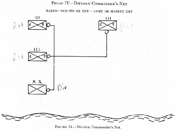
The division command net is shown completely manned on shore.
--60--
Phase IV--Amphibious Radio Channels
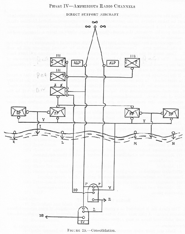
Section 9. Consolidation
- Upon the attainment of the primary objective, that of securing a beachhead, immediate action must be taken relative to the permanent communication set-up. Naval facilities afloat will be available for a limited time as the ships must be unloaded expeditiously and released. At the earliest possible moment, the signal officer must get ashore to make a thorough and an accurate estimate of the situation.
- Pre-operational intelligence will provide a certain amount of information as to existing facilities in the landing area. Communication requirements for tactical purposes will be well indicated. Thus, much of the planning and preparation for these requirements will have been accomplished. The factor that cannot be foretold with any degree of certainty is the amount of damage that the present facilities may suffer during the assault or through sabotage. In planning, liberal allowance must be made for this contingency.
- If the landings have been made in an area including a seaport, it is likely that a naval base will be established. In this circumstance, the division of responsibility between the military and naval commanders for the communications system (to include radar) must be determined. Normally, external communication with higher headquarters in the home country will be the responsibility of the Navy. Internal communications will embrace the task force headquarters and its subordinates (for example: task groups; supply, air, anti-aircraft, harbor and base installations).
- Close liaison between all officers responsible for signal communications must be maintained to coordinate the transition to the land-based system.
- Detailed consideration of the problem will include:
- Estimate of communication requirements.
- Time deadlines.
- Terrain.
- Existing facilities:
- Condition.
- Requirements for rehabilitation and extent to which these can be met.
- New installation:
- Matériel.
- Labor required.
- Personnel for operation and maintenance:
- Native.
- Military and naval.
- Alternate plans.
Section 10. Check List
- This check list is furnished as a general aid to the formulation of joint air-amphibious communication plans. A plan may omit items of the check list deemed inappropriate, and may include such additional items as may appear desirable.
- Information.--
- Date and hour when communication order or annex is to become effective.
- Enemy communications and radar.
- Friendly communications available for use.
- Limitations of intercommunication between services.
- Location of headquarters of participating services.
- Time.--
- Time system to be used.
- Time signals.
- Time tables (Sunrise-sunset, moonrise-moonset).
- Precedence (priorities).
- Information.--
--62--
- Radio.--
- General instructions, including radio silence, radio discipline:
- Use of plain language.
- Alternate arrangements in event of casualties to stations.
- Frequencies--Including time when becoming effective:
- Aircraft.
- Air-ground liaison (observation and reconnaissance).
- Air support.
- Armored force.
- Beacons.
- Boat traffic control.
- Broadcast (for example: Navy Fox).
- Command for transport divisions.
- Control for fighter aircraft.
- Control for commander of naval forces.
- Control for commander task force.
- Control for commander of fire support groups.
- Control and salvage vessels.
- Direct support aircraft.
- D/F for navigational aids.
- Fire spotting planes.
- Infantry division.
- International distress (SOS).
- Instrument landing.
- Meteorological.
- Inter-beach.
- Scene of action: (is an emergency frequency established by the combined chief of staff).
- Ship-to-Shore.
- Shore fire control parties to firing ships.
- Shore party lateral--used for relaying intelligence and action reports from landing points to the landing force commander still afloat.
- Intra-beach (between beachmaster, shore party commander and shore party message center).
- VHF.
- Call signs:
- Individual and block (group).
- International calls.
- Berne list.
- Encipherment.
- Organization:
- Army/Marine.
- Navy.
- Air.
- Joint. (Equipment and units for special purposes such as Navy gunfire liaison parties, shore party command, Army ground liaison with naval aircraft, ship-to-shore signal communications for Army command, air-support parties and controls (Army).)
- Authenticators:
- Systems.
- Methods.
- Nonmilitary communication systems:
- Surveillance.
- Allocation of stations to various services; and for propaganda purposes.
- Call signs.
- Frequencies.
- Modifications.
- Procedure radiotelephone (R/t), radiotelegraph (W/T).
- Joint.
Intra-service.
- Joint.
- General instructions, including radio silence, radio discipline:
- Radar.--
- Warning systems.
- Fighter control interception (FCI).
- Ground control interception (GCI).
- Siting.
- Interference with other services.
- Identification, friend or foe. (IFF).
- Aircraft interception. (AI).
- Beacons.
- Beam approach beacon systems (BABS).
- Aircraft surface vessel. (ASV).
- Surface search.
- Searchlight and fire control systems. (SL and FC).
- Radio and radar countermeasures.--
- Jamming by own side (deliberate).
- Jamming by enemy.
- Detection and identification.
- Frequency changes in event of jamming or interference.
- Deception.
- Communication and radar intelligence.--
- Information of enemy, radio and radar.
- Enemy stations, intercepting.
- Enemy stations, interfering.
- Reports of enemy sighting us.
- Interception of enemy radio and radar.
- Counter intelligence measures.
- Reports of interference.
- Enemy information reports.
- Monitoring of own transmissions.
- tracking.
- Direction and position finding.
- Distribution.
- Dummy traffic.
- Visual.--
- General instructions as to use:
- Restrictions.
- Choice of various means.
- Special pyrotechnic signals.
- Call signs:
- Individual and block (group).
- Time when effective.
- Channels to be set up between services.
- Procedure: Lights, flag hoist, panel and semaphore.
- General instructions as to use:
- Wire.--
- Responsibility for installation, operation, and maintenance.
- Organization of telephone and telegraph systems.
- To main base.
- Between main headquarters.
- Laterals between elements of different services.
- Antiaircraft requirements.
- Aircraft warning.
- Navy fire liaison parties.
- Air support.
- Air defense.
- Shore parties.
- terminal equipment requirements.
- Utilization of existing facilities.
- Special instructions:
- Telephone code names and numbers.
- Authenticator system, if necessary.
- Procedure.
- Teletype, teleprinter, and telegraph systems:
- Procedures.
- Call signs.
- Interchangeability.
- Nonmilitary facilities:
- Supervision.
- Allocation to services.
- Call signs.
- Modifications to normal procedures.
- Messenger Service.--
- Schedules:
- Airplane service--pick up and drop methods.
- Boat service.
- Ground messengers.
- Pigeon service.
- Special messengers.
- Whether officer or other rank.
- Schedules:
- Recognition and identification.--
- Policy.
- Types to be used, with effective times:
- Special approach doctrine for friendly aircraft.
- Emergency identification.
- Surface vessels, aircraft, submarines.
- Night fighting lights.
- Methods.
- Distribution.
- Security.--
- Instructions regarding communication and radar systems.
- Monitoring and supervision of own transmissions.
- Prompt exchange of technical information between cryptanalytic elements.
- Destruction of equipment when capture is imminent.
- Codes and ciphers.--
- Occasions when plain language may be used.
- Contact reports and methods of reporting positions.
- Systems to be used between various services with effective dates and restrictions, for example:
- Ship-to-ship visual code.
- Local allocation of signals in existing codes.
- Merchant ships.
- Visual codes, air-ground.
- Aircraft codes.
- Type to be used between higher headquarters.
- Fire control code.
- All-service emergency code.
- Emergency destruction of cryptographic aids and classified publications.
- Distribution (Holders).
- General.--
- Exchange of liaison parties between services.
- joint training for special personnel.
- Action to be taken in connection with captured equipment and matériel.
- Selection of equipment according to climatic conditions and terrain.
- Spares.
- Location of depots for signal stores. provision of special equipment.
- Service and maintenance organizations.
- Combat loading and distribution of equipment and personnel, including dispersal considerations to minimize possible losses.
- Prearranged message forms.
Section 11. Basic Communication Plan for Joint Operations
The joint communication plan will in general include the following items, which will be in the sequence indicated below:
- Information.--
- Such information of enemy communications and radars as may be essential from the point of view of joint operations.
- Such information of friendly communication and radar facilities as may be necessary for the coordinated action of the joint services in joint operations.
- Such information of the communication and radar systems of the participating services as may be necessary for the understanding by each service of the capabilities and limitations of the communication and radar systems of the other services.
- Such information of the aircraft warning service communication system as is necessary to insure the prompt reception and distribution of the information of approach of hostile and friendly aircraft.
- Such information regarding air support (naval and/or military) as may be necessary to insure that requests for air support will be expeditiously handled.
- Such information pertaining to the command "set-up" (that is, locating of the headquarters or command posts) of all services as may be necessary for the effective installation and operation of the communication and radar systems.
- Time.--Designation of the time systems to be used for communication purposes and in heading and text of messages.
- Precedence (priorities).--Establishment of various degrees of precedence (priority) and appropriate methods of indicating them.
--66--
- Radio.--
- General radio instructions, as necessary, including radio silence restrictions, etc.
- Call signs and frequencies, to include such instructions to cover assignment and distribution of radio call signs and frequencies as may be necessary to--
- Insure coordinated action and avoid interference between the services.
- Provide a guide for all services in distributing the particular items or publications.
- Indicate time when call signs and frequencies become effective.
- Instructions for the establishment and operation of such special channels of radio communication as may be required for joint operations, including--
- Assignment of personnel and special equipment when necessary.
- Operating schedules, etc.
- Authentication instructions.
- Special instructions regarding nonmilitary facilities, including supervision, allocation to various services, and designation of call signs.
- Coordinate inter-service requirements.
- Radar.--
- Radar search plans, designation of sectors to be searched by individual stations, based on capabilities and limitations of the equipment.
- Search doctrine (or policy), standard or special.
- Methods of passing Radar information, warning net.
- IFF (identification, friend and foe) instructions.
- Fighter direction procedures, instructions regarding GCI (ground control interception) and AI (aircraft interception).
- Radio intelligence.--Include such information and instructions as may be necessary for--
- Coordinated action of all radio intelligence services.
- Distribution (or exchange) of radio intelligence.
- Visual.--
- General instructions as necessary, including:
- Restrictions as to the use of visual signal equipment, daylight and darkness.
- Priority of various means (flags, searchlights, etc.)
- Meanings of special pyrotechnic signals.
- Visual call signs:
- Call signs needed for intercommunication between the services.
- Guide for the distribution of call signs to all interested elements.
- Time when call signs are effective.
- Designation of such visual codes as may be required for joint operations.
- Instructions for the establishment and operation of such special visual channels as may be required between elements of the participating services.
- General instructions as necessary, including:
- Wire.--
- Instructions for installation, operation, and maintenance of such wire communications as may be needed, including any restrictions.
- Organization of nets.
- Call signs needed for intercommunication between participating services.
- Special instructions regarding nonmilitary facilities, including supervision, allocation to various services, designation of call signs.
- Messenger service.-- Instructions for the operation of a messenger service between various elements which should state schedules, means of transportation, and whether officer or enlisted man.
- Recognition signals.--
- Recognition doctrine (or policy).
- List of the types to be used, day and night, with statements of time when each becomes effective.
- Recognition signals (surface craft, submarines, aircraft, and ground forces):
- Type or types to be used.
- Prescribed signals and maneuvers, including those used by aircraft approaching surface craft.
- Identifying marks on ships, special flags, lights, etc.
- Guide for distribution.
- Communication security and cryptanalytic activities.--Instructions to insure the coordination of the communication security activities, and the prompt exchange of technical information between cryptanalytic elements.
- Codes and ciphers.--
- Systems to be used, effective dates, and restrictions.
- Guide for the distribution of codes and ciphers.
- Equipment and personnel.--
- Instructions concerning liaison between services and the training and assignment of special personnel.
- Considerations of equipment of the various services, the limitations of use in areas of operation, available replacements, interchangeability, and spares.
- Grid system prescribed.--
- Recognition signals (surface craft, submarines, aircraft, and ground forces):
- Type or types to be used.
- Prescribed signals and maneuvers, including those used by aircraft approaching surface craft.
- Identifying marks on ships, special flags, lights, etc.
- Guide for distribution.
Sample Radio Channel Chart
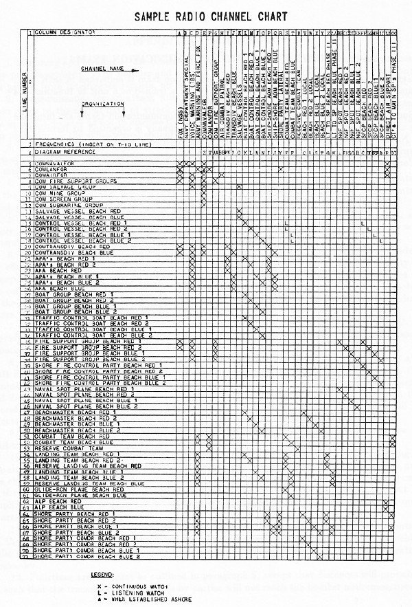
--69--
Appendix A--Joint Shore Party Communication Teams
- General purpose.--A joint shore party communication team is embarked in each APA. Each team, composed of both Army and Navy personnel, is trained as a unit to function as a unit in establishing communications on the landing beaches.
- Source.--Army Personnel of the joint shore party communication teams are furnished from the signal company, special (T/O 111-517S). Each company is organized to furnish nine teams. Naval communication ratings are assigned by commander amphibious force to complete these teams.
- Composition.--The composition of the joint shore party communication team is as follows:
Team officer (Army or Navy). Tech. Sgt. (Army/Marine). RM 3c (Navy). RM 2c (Navy). Pvt. (Army/Marine). RM 3c (Navy). Pvt. (Army/Marine). RM 3c (Navy). Pvt. (Army/Marine). RM 3c (Navy). Message center and messenger section: Staff Sgt. (Army/Marine). Pvt. (Army/Marine). Cpl. (Army/Marine). Pvt. (Army/Marine). Pvt. (Army/Marine). Traffic control boat: RM 3c (Navy). SM 3c (Navy). Visual and panel section: SM 2c (Navy). SM 3c (Navy). SM 3c (Navy). Wire section: Sgt. (Army/Marine). Pvt. (Army/Marine). Pvt. (Army/Marine). Pvt. Army/Marine). Pvt. (Army/Marine). Pvt. Army/Marine). Pvt. (Army/Marine). Pvt. Army/Marine). Pvt. (Army/Marine). Pvt. Army/Marine).
--70--
Appendix B--Air Support
- Bombing and strafing of the beach defenses, vital installations and immediate rear areas is by prearrangement. The number of type of targets so selected will depend upon information gained from intelligence reports, air reconnaissance (including photographic), spies, etc.
- Reconnaissance for an attack will, if practicable, take place during a period of several weeks prior to the actual date of attack. This reconnaissance will be conducted over a wide area in such a manner as not to disclose the proposed point(s) of landing. Bombings which may take place during the same period should be designed to soften and mislead the defense.
- It cannot be expected that missions by prearrangement will neutralize all major points of enemy resistance. To meet this contingency, a system of air support is set up whereby bombing missions are carried out "on call" or by request.
- The communications herein discussed, as they pertain to land based planes, is predicated on the assumption that one air support command will support the landing of one infantry division.
- When carrier based aircraft are used, the air liaison party will consist of one naval air officer, one radioman, one Army air officer, and one radio operator technician. The party will be equipped with an SCR-193, preferably on a one-quarter-ton vehicle.
- Normally this party will be transported in the same ship as the combat team commander, the officers becoming part of his staff. Upon debarkation and movement to shore, the party is transported in a boat adjacent to the combat team commander and, when ashore, operates at the command post of said commander. If the situation demands, this party may be directed by the combat team commander to travel and operate with the headquarters of one of the landing teams.
- An air support control (naval), composed of a naval air officer and staff sufficient to provide communications and to maintain the necessary records (availability of aircraft, losses, situation map, etc.), is set up aboard the headquarters ship.
- During the early phases of the landing operation, it is essential that direct support aircraft be on "air alert," and that requests form air liaison parties be transmitted direct to the commander of the direct support aircraft. The air support control monitors these requests and determines the priority in the event of multiple or conflicting requests. In the event the aircraft detailed for direct air support are equipped with VHF radio only, the requests will be directed to the air support, who will issue the attack order on the proper frequency.
- When there are suitable bases near enough the scene of attack to permit the use of land-based aircraft, these should be used in place of carriers.
- In this case, a control squadron (Avn) will furnish air support parties each consisting of one air officer, one communication officer, two radio operators, two radio operator-mechanics, and one chauffeur. They travel with, serve, and function with the same headquarters as in the case of the air liaison party (Naval). This party is normally equipped with the SCR-299, but in amphibious operations, a more easily transported set such as the SCR-193 mounted in a one-quarter-ton vehicle must be procured.
- The control squadron (Avn) will also provide the personnel for the air support control on the headquarters ship. Composition: one air officer, one communication officer, one chief radio operator, two assistant chief radio operators, four radio operators, and two radio operator-mechanics.
- Functions are the same as outlined in paragraph 8, except that distances will probably be such that the transmission of requests by parties will not reach the bomber airdromes, necessitating another channel (from control to airdrome) for the repetition of necessary information in the bomb attack order.
- The attack order officially goes to the bomb group headquarters, but the squadrons listen to the transmission from control to group, and can be ready (alerted, armed, briefed) when group gives the order to execute.
- An observation liaison officer is provided and functions at the command post of the ComLanFor, when afloat or ashore. He is provided communication with the land based observation group. He works in close coordination with the ComLanFor, ComNavFor and ComAirFor and controls air observation activities.
- Air support command on the friendly shore keeps informed of the air situation through its own channels and is kept informed of the general situation through ground force channels, thus is able to take over air operations if circumstances demand.
- The air support control aboard ship is equipped with high power VHF in addition to HF for contact with fighter and other aircraft so equipped. It is advisable that air support parties and/or air liaison parties be equipped with low power VHF for the same purpose.
Air Support Nets (Support Group Land Based)
Radio--SCR193 or 284, SCR-299, BC-342 Revrs.)
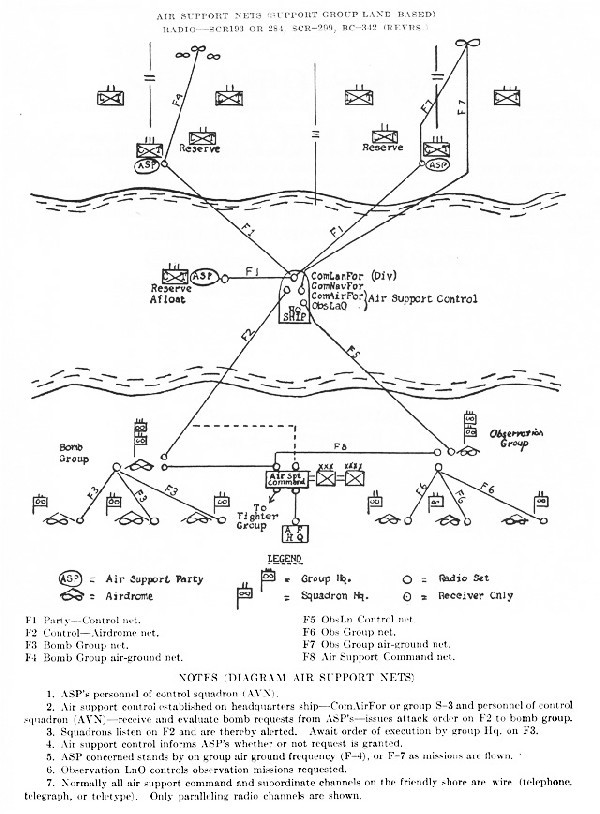
Appendix C--Air Defense
- Fighter aircraft (AAF and Naval) employed in air defense perform two functions in amphibious operations, namely:
- To provide an escort for air support airplanes. A communication channel must be provided linking fighters, escorted airplanes and fighter control, the latter to be either aboard headquarters ship, aircraft carrier, fighter direction ship or on friendly shore.
- To provide a fighter cover for landing operations in case of an attack by enemy aircraft. Fighters will require communications with fighter control on headquarters ship, aircraft carrier, fighter director ship or friendly shore. Naval radar will provide AWS and direction finding for fighter control.
--74--
Chapter IX. Hydrographic and Beach Markings

b. Boat channel.--
1. Right side of channel (from seaward)--
Day--Red pennant on buoy.
Night.--Shielded red light.
2. Left side of channel (from seaward)--
Day--Black pennant on buoy.
Night--Shielded white light.

- Beach markings.--The markings described herein are to be of the same color as the name of the beach. The examples below are for Beach Red and Beach Red Two.
- Left flank (from seaward):
Day--A solid color rectangular panel mounted horizontally. A suitable size for a single panel has been found to be approximately 12 feet long by 21/2 feet wide.
Night--A single colored light and a steady white light, mounted horizontally, the colored light to be inboard (toward the center of the beach).
- Left flank (from seaward):

b. Right flank (from seaward):
Day--A solid rectangular panel, the same as the left flank panel, mounted vertically.
Night--Two steady colored lights, mounted horizontally.
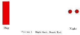
c. The following examples indicated the use of the markers when the color name of the beach is duplicated.

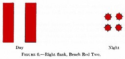
--80--
d. Beach center marking.--When it is desired to mark the center of other interior point of a beach, the following markings (of the same color as the beach) are to be used, either alone or in conjunction with the flank markings:
Day--A solid color square panel.
Night--A single steady colored light.

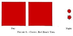
904. Landing point markings.--Landing points are marked on the beach as required in order to indicate to coxswain the points at which boats should land according to the load which is carried. The prescribed markings are shown below. A suitable size for landing point panels has been found to be approximately 6 feet square.
Improved--The beach inland from the point so marked is passable for wheeled vehicles. If desired, this marking may be combined on the same standard with any other landing point marking.
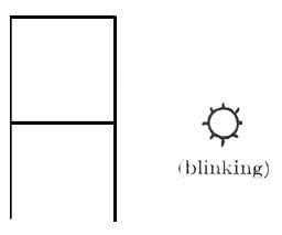
--81--
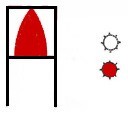


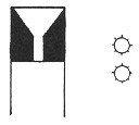

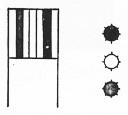
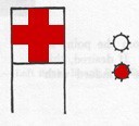
905. Ranges.--In case the negotiation of a seaward approach makes the establishment of a range practicable or desirable, ranges will be established by the erection of a duplicate landing point marker at the proper elevation and direction to landward of the landing point involved.
Chapter X. Landing Boat Material
Section 1. General Information
- Correspondence.--All correspondence regarding landing equipment shall be classified "RESTRICTED."
- Operator's manual, engine parts and instruction books.--Parts and instructions books for the engines of all landing boats as well as an operator's manual for Higgins Eureka boats, are available for issue by the nearest Naval Landing Force Equipment Depot. Vessels may obtain these books by submitting a request direct to the Commander appropriate Naval Landing Force Equipment Depot.
- Engine records.--
- Log books have been provided for the engines of landing boats. These books contain detailed instructions for the entries required to be made therein.
- Upon removal of an engine from a boat, an appropriate entry shall be made in the log book giving the reason for its removal. When engine changes occur, a report shall be submitted to the Bureau of Ships, with copies to Commander transports, Commander Amphibious Force, and Commander appropriate Naval Landing Force Equipment depot, giving serial number of the hull; Bu. Ships and manufacturer's serial number of the engine removed; Bu. Ships and manufacturer's serial number of the engine installed, and the disposition of the engine removed.
- When engines are transferred from one ship to another, or from a ship to the depot, or vice versa, a report shall be made to the Bureau of Ships with a copy to Commander transports, Commander Amphibious Force, and Commander appropriate Naval Landing Force Equipment Depot.
- Whenever a boat or engine is transferred from one ship to another or is returned to a Naval Landing Force Equipment Depot, the log book shall be completed, signed, and forwarded to the ship or activity receiving the boat or engine.
- Spare parts procurement.--
- Commanders Naval Landing Force Equipment Depots are responsible for the procurement of all spare parts and equipment required for the maintenance of all special landing boats for vessels of the Amphibious Forces.
- Material obtained from the Naval Landing Force Equipment Depot for the repair and maintenance of landing boats will be invoiced to the requisitioning vessel or activity as a charge against that vessel's Bureau of Ships general order allotments.
- Requisition swill be submitted on S & A Form 44 and addressed to the appropriate Naval Landing Force Equipment Depot, and not to a Naval Supply depot, as the latter activity has no connection with the procurement and issued of this material.
- In the preparation of requisitions, parts numbers or catalogue numbers will be given. In the absence of this information, a full description of the item desired should be given for identification.
- The commanding officer of each APA or AKA will initiate the necessary action to obtain and maintain sufficient spare parts for equipment assigned to his command.
- Do not submit requisitions to Naval Landing Force Equipment Depots for material obtainable from standard stock.
- Original boat equipage.--
- The issuing Naval Landing Force Equipment Depot provides the initial outfit of equipage for issue with each boat. Replacement of lost or damaged equipage thereafter is the responsibility of the vessel to which the boat is issued.
- When boats are being returned to the Base for exchange or repairs, outfits of equipage will be removed prior to the return of the unit to the Depot, and will be retained on board for reinstallation upon the return of the unit to its ship.
- Spare engines.--
- It is the policy of the Bureau of Ships to provide 1 spare engine for every 10 units carried on board all vessels equipped with landing boats. In the case of those vessels having more than 10 units assigned, 1 spare engine will be provided for each 10 units or major portion thereof.
- Each APA and AKA will procure and maintain its quota of engines.
- Engines will be issued on written request to the appropriate Commander Naval Landing Force Equipment Depot. It is understood that there will be no charge to the ship's allotment for the cost of these engines.
Section 2. Repair and Maintenance Facilities
- Repairs.--
- The repair and upkeep of landing boats regularly assigned to a vessel is the responsibility of the commanding officer. The Bureau of Ships has directed that repairs beyond the capacity of the ship's force be accomplished at the several Naval Landing Force Equipment Depots, where repair facilities have been established for this purpose. Requests for repairs, beyond the capacity of the ship's force, will be submitted to the Commander of the nearest Naval Landing Force Equipment Dept., on a standard Navy Yard Repair request, Form N. S. O. (105). Requests for repairs to landing craft shall be forwarded via the chain of command. This article shall not be construed as prohibiting the accomplishment of emergency repairs by activities other than the depot, the necessary parts or equipage being provided by the ship or obtained from the depot by the activity accomplishing the repairs.
- Cost of repairs.--The cost of material or equipage, expended by the Commander Naval Landing Force Equipment Depot, in effecting repairs to landing craft regularly assigned to a vessel, will be invoiced as a charge against that vessel's general order allotment.
- APA and AKA ship facilities.--
- Boat engine repair shop.--
- Set valve refacing equipment.
- Set valve seat grinding equipment, with grinding wheels for each type engine carried.
- One 9- by 3-inch bench lathe with collect chucks (may be provided in machine shop).
- Bench milling machine (may be provided in machine shop).
- Bench grinder.
- Sensitive drill, column bench (may be provided in machine shop).
- Champion spark plug cleaning equipment.
- Megger.
- Electric tachometer.
- Two 11/2 ton chain falls.
- Nozzle test (for GM, etc., Diesel engines).
- Two propeller pullers, one large and one small.
- Hydraulic arbor press, minimum capacity 5 tons (to be provided in machine shop).
- Power hacksaw (to be provided in machine shop).
- Engine compression gage.
- Vacuum gage.
- Set copper tube flaring tools.
- Set dies and taps (SAE).
- Set die nuts (SAE).
- Cylinder hone for each type engine carried.
- One 1/4-ton chain fall.
- Vise, pipe.
- Vise, 4-inch.
- Key seating machine.
- Carpenter-shipfitter shop.--
- Arc welding machine, 300 ampere (portable gasoline or Diesel drive one preferred).
- Drill press, 1/2-inch, Jacobs chuck.
- Circular saw, 12-inch blade.
- Boat engine repair shop.--
4. Sheet metal brake, 48-inch, 16-gage capacity.
5. Band saw, 14-inch wheels.
6. Two oxyacetylene cutting torches, with tips and one spare tip.
7. Two oxyacetylene welding torches, with tips and one spare tip.
8. Four regulators and gages for above.
9. One portable sander, 10-inch disk type.
10. Two woodworker's vises.
11. Power joiner, planer, 6-inch blades.
12. Bench grinder, 3/4 by 1 by 10 inches.
13. Hand shears, capacity 1/8-inch metal.
14. One 30-pound riveting hammer, pneumatic.
15. One 60-pound riveting hammer, pneumatic.
16. Two dolly bars, for riveting.
17. One air jam.
18. Air hose, 200 feet.
19. Two jacks, hydraulic, 2-ton.
20. Blacksmith's anvil, 240-pound.
21. High-speed portable grinder (only part of propeller reconditioning outfit required on individual ships).
c. Additional allowances for division flagships.--
1. Electric oven, sufficient capacity to accommodate generators in tank lighters.
2. Commutator undercutter.
3. Armature rewinding machine.
4. Propeller reconditioning equipment, consisting of the following items:
a. Pitch block base.
b. Pitch block for each type of propeller.
c. Polishing wheel.
d. Two portable high speed grinders.
e. One propeller balancing stand, Sundstrand No. 2.
Note 1.--Propeller reconditioning equipment may be supplied by the nearest Naval Landing Force Equipment depot.
Note 2.--All other equipment is obtainable only if on bureau of Ships Hull or Machinery Allowance Lists.
- Special engine tools.--Requisition from the nearest Landing Force Equipment Depot (Catalog 41, Landing Force Supply Catalog). Recommended in addition to special tools furnished in parts boxes:
Stock No. Item Specification Unit of
quantityQuantity
requiredB-1425/GD Blocks, injector valve lapping J-1330 No. 2 C-2110/GD Cleaner, spray tip driver and injector bushing J-1291A No. 2 C Cleaner, valve guide KMO-122 No. 4 C-2220/GD Compressor, piston ring KMO-231 No. 1 E-250/GD expander, oil seal, flywheel housing J-1359 No. 1 F Fixture, connecting rod and piston bushing reaming J-1506 No. 1 F-2000/GD Flange and driver, injector tube J-1229 No. 1 G Gauge set, feeler J-1523 No. 1 G Gauge, timing, fuel injector J-1564 No. 2 G Gauge, valve lash feeler KMO-233 No. 1 H Hone, cylinder, 1/2-inch drive KMO-1000-D No. 1 I Installing set, connecting rod needle bearing J-1235 No. 1 J-200 Jaws, injector, body vise (with popping tool) J-1261A No. 2 L-400/GD Lapper, valve KMO-239 No. 1 L-1460/GD Lifter, spring injector valve J-1290 No. 1 P-2800/GD Protector, camshaft oil seal J-1509 No. 1 P Puller, blower, rotor gear J-1228 No. 1 P-2940/GD Puller, main bearing cap J-1472 No. 1 --85--
Gray Diesel marine engine.--Continued.
Stock No. Item Specification Unit of
quantityQuantity
requiredP Pyrometer, exhaust manifold heat KMO-328 No. 1 R-2300/GD Reamer set, injector tube J-1231 No. 1 R-2303 Reamer set, valve seat KMO-234 No. 1 R-2305/GD Reamer, valve stem guide finishing J-192-2 No. 2 R-2310/GD Reamer, valve stem guide roughing, .341 J-714 No. 2 R Reaming fixture, connecting rod and piston bushing J-12-1506 No. 1 R-2400/GD Remover, broken push rod and cam follower J-1244 No. 1 R Remove, injector tube J-1232 No. 1 R Remover, and replacer, piston pin cam and rod checking valve J-1234 No. 1 R-2410/GD Remover, push rod J-1245 No. 1 R-2420/GD remover, and replacer, piston ring KMO-232 No. 1 R Remover and replacer cylinder sleeve, hand operated J-1479 No. 1 R-2425/GD Remover and replacer set, piston pin bushing J-1513 No. 1 R Remover, valve spring compressor and injector J-1227 No. 1 R-2430/GD Remover and replacer, valve stem guide J-1233 No. 2 S Service set, injector J-1241 No. 2 S Socket, 11/4-inch SW-40011/2 No. 1 S-4150/GD Spreader, blower drive gear, flexible coupling spring J-1471 No. 1 T-3140/GD Tool, flaring, fuel line J-978 No. 1 T-3175/GD Tool set, fuel pump J-1508 No. 2 W-651 Wrench, box, open end 15/16-inch No. 1 W Wrench, fuel pump KMO-326 No. 1 W-1380 Wrench, governor adjusting CS-1146 No. 1 W-1400 Wrenches, injector filter cap KMO-240 No. 1 W Wrench, injector nut J-1238 No. 1 b. Hall-Scott gasoline engine.--Any general automotive tools. (Plomb Tool Co. Catalogue.)
- Hand tools for boat engine repair shop.--
1 oil stone.1 12 blades, hack saw.1 1-14 file, coarse.1 2 handles, file.1 3 files, half round, small, medium and large.1 3 files, rat-tail, small, medium and large.1 3 files, mill, small, medium and large.1 6 wedges, steel, small, medium and large.1 1 valve guide puller set.2 1 brush, small wire.1 1 set punches, gasket, from 1/8 inch to 1 inch.1 5 wrenches, monkey, 6-, 8, 10-, 12, and 14-inch.1 1 compressor, ring.2 1 mallet, raw hide.1 1 maul, copper.1 1 scraper, carbon.3 1 scraper, gasket.3 1 set of easy outs, 9 pieces.3 1 tube cutting and bending set.3 2 pullers, propeller, large and small.4 1 indicator, dial.3 1 set wrenches, Allen set screw for 1/8. To 3/4-inch, No. 2381 and No. 2383.3 2 sets scraper, bearing, small and large.1 1 file card.1 1 valve spring compressor, large.1
- Hand tools for boat engine repair shop.--
| 1 | 100-piece socket set.1 |
| 1 | punch and chisel set, 12 piece.3 |
| 1 | wrenches, crescent adjustable, 4-, 8-, 10-, and 12-inch.3 |
| 1 | wrenches, pipe, 6-, 8-, 10-, and 12-inch.1 |
| 1 | drill, breast, straight shank to 1/2-inch.1 |
| 1 | gage, thickness, 0.002 to 0.025.3 |
| 1 | tap and die set, SAE, Fulton 12-piece,1/2-inch to inch.1 |
| 1 | ignition set, 10 piece, 3,200 C. Plomb.3 |
| 1 | lifter, valve.2 |
| 1 | twist drill set, 1/16- to 1/2-inch by 64ths.1 |
| 1 | drill, electric, up to 1/2-inch.1 |
| 1 | spark plug set, Plomb 5 piece, deep 5,300 C.3 |
| 1 | stud puller.3 |
| 1 | grinder, valve, hand, oscillating.3 |
1. Obtained from standard stock.
2. Obtained from engine manufacturer through Naval Supply Depot.
3. Obtained locally from dealer through Naval Supply Depot.
4. Manufacture on board.
- Material for maintenance of landing boats.--
- Experience indicates that a variety of material, in addition to spare parts for engines, is required for the maintenance of landing boats. The following general list is promulgated for information and guidance:
Anchors (for boats and tank lighters).
1. For boats manufactured by Higgins Industries Inc.
Batteries, storage (one spare for each three installed).
Beading.
Bearings, stern tube (50 percent spares).
Belts, V.
Blower.
Bulbs, light.
Cable, electric, rubber insulated.
Cable, flexible (for wheel ropes, anchor cable and ramp cables).
Cable, ignition.
Clamps, hose.
Cylinder, vacuum, power.1
Cylinder, vacuum, storage.1
Glass cylinders (for sand traps).2
Horn, electric.
Hose, rubber, water, various sizes.
Lights, running, port and starboard.
Oil, neat's-foot (obtained in 5-gallon cans--standard stock).1
packing, waterproof (for pumps).
Plywood.1
Post, rudder.2
Propellers (two spares for each shaft).
Pulleys, V-belt.
Pumps, fresh water.
Pumps, gasoline or fuel oil.2
Pumps, lubricating oil.
Pumps, magnetic (autopulse).1
Pumps, salt water.
Pumps, vacuum.
Quadrant, rudder (50 percent spares).2
Rudder.
skegs (one for ramp boats and one for landing boats.)2
Switches, various.
Tools, Craftsman master set (at least two sets, and preferably four sets for large vessels). Traps, sand (one complete trap for each type of boat.)2
Tube fittings, various.
Tubing, copper, various sizes.
Valve, vacuum, remote control.1
Wheel, steering.
2. This equipment varies with type of engine and manufacturer of boat.
- Experience indicates that a variety of material, in addition to spare parts for engines, is required for the maintenance of landing boats. The following general list is promulgated for information and guidance:
--87--
b. The information given is not sufficient for the purpose of preparing requisitions, but is intended to direct attention to various items which should be obtained and carried aboard APAs and AKAs.
c. Material other than standard stock can be obtained from the nearest Naval Landing Force Equipment Depot.
Section 3. Special Directives
- Engine speeds.--
- For normal operations, engine speeds of 1,700-1,800 r.p.m. are authorized, except when boats pass near ships, other boats, in the vicinity of docks, landings, or in restricted channels. Under these conditions, engine speeds shall be limited to 800 r.p.m. When LCVP and LCV are used as ship's running boats, engine speed shall be limited to 1,500 r.p.m., due to poor visibility ahead at high speeds.
- During landing operations, maximum engine power shall be available, therefore, no throttle-limiting stops shall be employed on gasoline engined boats and governors of Diesel engines shall be set to permit maximum r.p.m. during these periods.
- The above does not prohibit the commanding officer of any vessel from placing restrictions upon the operation of engines, which may, in his judgment, be necessary in order to conform to good engineering practices, at times other than during actual or practice landing exercises.
- Use of propeller reconditioning equipment.--
- Each division flagship should be provided with equipment necessary for reconditioning of all landing craft propellers. It is intended that division flagships recondition the propellers for the landing craft of all vessels assigned to that division. In order not to place an undue hardship on the personnel of the division flagship, vessels sending propellers to division flagships for reconditioning shall detail personnel to assist. In order that personnel may become proficient in the reconditioning of propellers, all damaged propellers of landing craft assigned to transports of the Amphibious Forces shall be reconditioned in accordance with the procedure outlined herein. Vessels not having personnel trained in the reconditioning of propellers shall arrange with the Commanding Officers, Naval Landing Force Equipment depot, for the training of such personnel.
- Measures to insure easy removal of propellers.--In order to insure easy removal of propellers during an operation, all propellers installed on landing craft shall be removed periodically, the shaft shall be cleaned and coated with a mixture of white lead and oil prior to reinstallation of the propeller.
- Emergency tiller.--The emergency tiller provided with each boat shall be available and readily accessible at all times. The protective deck plate (installed over top of rudder post and removed when emergency tiller is shipped) shall be removed before all landing exercises in order that the emergency tiller may be readily installed, should such be necessary.
- Ramp operating gear.--
- A number of failures of ramp cables and hoisting gear of landing boats have occurred during landing exercises. If, after unloading at the beach, the crew is unable to hoist the ramp of a boat, the problem becomes a serious one, inasmuch as the boat may be swamped if headed into a sea with the ramp down.
- All APAs and AKAs shall take action to equip LCM(3)s and vehicle ramp boats with a positive means for the manual operation of ramps. Two wire pendants and two jiggers are suggested, as these have worked well during past exercises.
- The Landing Force Equipment Depot is authorized to provide 1 spare set of ramp hoisting gear, complete, for each 10 (or fraction thereof) of LCVP, and LCM(3) issued to APAs and AKAs. Such issue will be considered as part of the boat equipment and not as part of the ship's allowance list.
- Ramp and ramp operating windlass--LCV and LCVP.--
- The ramp and ramp operating windlass of LCV and LCVP must be kept in excellent mechanical condition and well lubricated at all times.
- Prior to lowering ramp, for debarkation of troops, or vehicles, on the beach, remove hand crank from windlass. If it is necessary to regulate speed at which ramp is being lowered, use windlass brake. The above precaution is necessary to obviate injury to personnel. In order that the hand crank will not be lost overboard it shall be secured to the windlass with a suitable lanyard.
--88--
- Emergency equipment.--Each boat shall carry:
- One 5-gallon can of lubricating oil of correct viscosity. (This lubricating oil should be carried for emergency use only, and should not be the can from which oil to replenish that consumed is to be take
- One 5-gallon g can of fresh water, for emergency use. (This item will be carried, without fail, in those boats where the salt water systems are not arranged in such a manner that the two systems can be cross-connected).
- Tiller, for emergency use, stowed where readily accessible.
- Clutch lever, or section of pipe, for use in event of casualty to remote control system.
- A tool kit containing sufficient tools for effecting emergency repairs.
- At least six spark plugs (in gasoline engined boats).
- One roll of friction tape.
- One bucket.
- Notes on operation and maintenance--Fresh water cooling systems.--
- Unsatisfactory operation of the fresh-water cooling system has, in a number of cases, been traced to the fact that the system becomes air-bound during filling, and that after the engine has been started, circulation of the water permits the air to escape, resulting in the system being only partially filled.
- To guard against unsatisfactory operation from this cause, it is directed that the following procedure be observed during the period the fresh water system is being filled:
- If practicable, keep the engine turning over during this period.
- If impracticable to keep engine turning over during the filling period, immediately after the boat is hoisted out for operations, start the engine and recheck the quantity of fresh water after the engine has been turning over for a few minutes.
- Antifreeze solution.--An approved antifreeze solution shall be used in the fresh-water system. Alcohol shall not be used for this purpose.
- Heat exchangers.--Heat exchangers become filled with sand, and the tubes become fouled by oil deposits, etc., in service. As this results in a reduction of the heat-transfer capacity of the exchanger, it is necessary to withdraw the tube nests at periodic intervals and remove sand, etc., After the foreign matter has been removed, it will be necessary to remove the oil and other deposits from the tubes by the best method available. While immersing the tube nests in a strong solution of boiling water and boiler compound or lye will probably be effective, the best procedure is to clean the tubes in a diluted solution of muratic (hydrochloric) acid, where facilities are available.
- Vee-belt adjustment.--In many cases the cause of unsatisfactory operation of a cooling water system may be traced directly to an improper adjustment of the V-belts used on all landing force equipment. Should the cooling system be giving trouble, the adjustment of V-belts should be checked.
- Magnetic switches.--Much trouble has been experienced with the magnetic switches, due to the fusing of the points of these switches. One of the causes of this trouble has been attributed to the use of storage batteries having an insufficient number of plates. This condition results in a pronounced initial voltage drop which subsequently results in a weak magnetic field for the switch. This causes chattering and pitting of the points, resulting in the fusion and welding of these points. Coxswains and engineers shall be carefully indoctrinated in the correct procedure to be observed when operating magnetic switches.
- Cold weather precautions.--
--89--
c. Use appropriate antifreeze preparation, such as "Prestone," in the fresh water cooling system. Obtain and use a suitable hydrometer to determine proper specific gravity of solution.
d. Use appropriate grade of lubricating oil.
e. Starting will be improved by applying steam to engine compartment and heating circulating water.
Section 4. Lubricating Oils
- Variety required.--As APAs and AKAs may be required to operate on short notice, under climatic conditions varying from those encountered in Arctic regions in the winter to those encountered along the Equator in summer, it is of the utmost military importance that each vessel be provided at all times with the necessary variety of lubricating oils to enable it to be self-sustaining in any area or under any climatic conditions. Based upon experience, the following lubricating oils are recommended:
1 The Bureau of Ships has directed that only these oils be used in Gray Diesel engines. This oil is especially designed for heavy duty service encountered in high-speed diesels. Use of an oil other than the above will result in unsatisfactory engine operation, due to carbon deposits, sticking rings, etc.Operating conditions Gasoline
engines--
Navy
symbolDiesel
engines1
Navy
symbolS.A.E.
equivalentFor heavy duty and high temperatures 3080 9370 40W For medium duty and temperatures 3065 9250 30W For temperatures below freezing 3050 9170 20W For extremely low temperatures 1042
2075
22101042
2075
221010W - Identification.--The following symbol system is employed in the naval service for identification of lubricating oils: A four-digit identifying symbol is used in all cases, the first digit indicating the class of oil and the last three digits indicating the viscosity. viscosity at 130° F. is used for class 2 forced-feed oils, and for compounded air-cylinder oils. Viscosity at 210° F. is used for class 1 aviation oils, for class 3 forced-feed oils, for compounded marine-engine and cylinder oils, and for mineral marine-engine and cylinder oils.
- Classes.--The classes of oils indicated by the first digit are as follows:
- Forced-feed oils, high V.I. (aviation) (1).
- Forced-feed oils, low V.I. (2).
- Forced-feed oils (medium V.I.) (3).
- Compounded marine-engine oils (4).
- Mineral marine-engine and cylinder oils. (5).
- Compounded steam-cylinder oils (tallow) (6).
- Compounded steam-cylinder oils (lard or tallow) (7).
- Compounded air-cylinder oils (8).
- Diesel engine oil (heavy duty) (9).
- For the benefit of those desiring to use oil obtained under Navy Department contracts for the lubrication of equipment manufactured by commercial concerns, where reference is made to S.A.E. lubricating oil specifications, the following table shows the Navy symbol for lubricating oil corresponding approximately to the various S.A.E. numbers.
S.A.E. rating | S.A.E. rating specified: Use Navy symbol | specified: Use Navy symbol 10W 1042. | 40 3080, 1080, or 9370. 10 2110. | 50 3100 or 1100. 20W 1047. | 60 3120 or 1120. 20 3050 or 9170. | 70 1150. 30 3065, 1065, or 9250. | 600W 5150 or 5190.
--90--
- Attention is invited to specifications for lubricating oils of classes Nos. 1 and 3, which require that these oils maintain their viscosity at 21-° F., whereas class No. 2 oil is only required to maintain this viscosity at 130° F. Therefore, except in an emergency, class No. 2 lubricating oils will not be used in landing boats except where a lubricating oil having a viscosity of 10W is required. In the event that delivery of class No. 3 or No. 9 lubrication oil cannot be obtained, class No. 1 of the equivalent viscosity will be substituted.
- Much of the bearing trouble encountered in the operation of internal-combustion engines can be attributed to the use of a lubricating oil which does not meet the load and temperature conditions under which the engines are operating. Boat maintenance and operating personnel will be carefully indoctrinated in the selection of the correct class of lubricating oil to meet the requirements of the conditions under which the engines are being operated.
NOTE:--Bureau of Ships Pamphlet NBS No. 341 covers the properties of the various Navy symbol lubricating oils in detail. Vessels not having a copy of the pamphlet will obtain one, by letter, from the Bureau of Ships.
Section 5. Engine Operating and Maintenance Instructions
- All boat operating personnel including boat officers and coxswains shall become proficient in the following:
- All safety precautions.
- Preparation of the engine for starting.
- Starting of engine.
- Know location of and be able to clean:
- Gasoline or fuel strainers.
- Lubricating oil purifier.
- Sand traps.
- How to change from fresh to salt water cooling.
- Shift the clutch from vacuum to manual.
- Vent fresh-water pump, to free it of air.
- Start engine when starter solenoid switch has failed.
- Make necessary adjustments to clutch in both ahead and astern positions.
- Normal operating temperatures and pressures to be expected.
- Minor casualties to electrical system and corrective action, including connection of batteries in series.
- Purge Diesel fuel-oil system of air.
- Replenish oil in an emergency.
- Effecting emergency repairs to lubricating oil system, cooling system, and electrical system, as a result of damage sustained under combat conditions (such as repairs to piping by using rubber hose, replacement of damaged sections of tubing, repairs to fuel tanks and cooling water system by use of plugs, repairs to electrical and ignition systems, etc.). Ships will provide in each boat or lighter, a supply of rubber hose, hose clamps, hacksaws and blades, tapered wooden plugs, etc., for this purpose.
- Routine engine inspections.--
- Prior to being hoisted out.--
- Inspect for gasoline or fuel-oil leakage.
- Inspect bilges to see that they are dry and free of gasoline or gasoline vapor.
- Operate the hand bilge pump for at least 5 minutes after it has ceased to discharge water.
- Inspect electrical system for grounds, short circuits, chafing, or other defects which may result in a spark.
- Raise the cowl on the engine hood prior to starting. Keep cowl raised until engine is operating satisfactorily.
- See that flame arrestors are in place, properly secured.
- Check wheel rope for adjustment. Adjust as found necessary.
- Prior to being hoisted out.--
--91--
8. Recheck the following:
a. Lubricating oil.
b. Gasoline or Diesel oil.
c. Fresh water.
d. Sand traps for cleanliness.
9. Start the engine room exhaust blower and operate for at least 5 minutes.
b. After hoisting out.--
1. Before starting engine:
a. Open necessary valves in fuel and cooling systems.
b. Prime the engine.
c. Turn switch on position marked "Engine and Blower."
d. Press starter button.
2. After engine has started, haul away from ship's side as directed and lay-to for a period of 5 or 10 minutes. Keep engine idling at approximately 400 r.p.m. until engine has warmed up. During this period, check the following for satisfactory operation:
a. Cooling water for temperature and volume.
b. Lubricating oil temperature and pressure.
c. Electrical system.
d. Ignition system.
e. Remote control system.
f. Operation of boat steering gear.
g. Turn ignition switch to position marked "Engine."
c. During operation.--
1. Keep a constant check on the following items:
a. Operating r.p.m. of engine.
b. Charging rate of generator.
c. Lubricating oil for pressure and temperature.
d. Cooling water temperature.
f. Sand traps (for cleanliness).
NOTE.--Sand traps should be tended constantly during landing exercises. As soon as there is any indication of a deposit of sand in the trap, the cooling water suction should be shifted and the fouled trap cleaned. There is no acceptable excuse for shifting to a clean strainer and failing to clean the fouled strainer immediately.
d. At the end of each period of operation.--
1. Check and replenish as necessary:
a. Lubricating oil.
b. Gasoline and diesel oil
c. Fresh water.
2. Effect any repairs required, or report list of needed repairs to boat repairmen.
3. Take necessary action to replenish any material, normally carried in the boat, which may have been expended during the day's operations.
4. Whenever freezing temperatures are expected, drain all fresh water from the engine cooling system, unless protected by antifreeze or other approved methods. When temperatures below 27° F. are predicted, carefully drain all of the salt-water system, including bilge drainage system.
5. Clean:
a Gasoline or fuel-oil strainers
b. Lubricating-oil purifiers.
c. Sand traps.
6. Test battery electrolyte for condition of charge. (This is of particular importance during low temperatures. It is of the utmost importance that storage batteries be kept fully
--92--
charged, in order that there be sufficient energy to turn the engine over on a cold morning. There is also danger of the battery solution freezing if the state of charge is low.)
7. Lubricate all working parts of the remote control system; fill all other oil and grease cups and set up on grease cup caps. Inspect and set up on packing gland nuts where necessary.
1033. Inspection prior to an amphibious operation.--In order to insure that landing craft will be ready when required, commanding officers shall insure that the following directives are accomplished:
a. Remove deck plate over rudder posts and stow.
b. Insure that all storage batteries installed are kept fully charged (test daily).
c. Insure that all ramps operate. Free up and lubricate hinge pins, ramp cable sheaves, ramp windlass, etc.
d. 4.Insure that hand crank for ramp windlass, emergency tiller, hand crank for anchor windlass (where installed) and clutch control lever for manual operation of clutch of engine in Higgins type boats (in event of failure of vacuum clutch control) are in landing craft and stowed where readily accessible when boats are loaded.
e. Remove all propellers and lubricate shafts with mixture of white lead and lubricating oil to insure easy removal in an emergency.
f. Insure that life rings are not stowed in LCV where they will foul ramp cable sheaves.
g. Insure that anchors are shackled to anchor lines, and are stowed where they can be used when boat is loaded.
h. Check steering gear controls to insure that rudder travel is equalized. In some of the Chris-Craft boats the gears in the rudder control system have been meshed without the rudder first being placed in the midposition. Adjustment of the rudder control cables in other boats may have resulted in a similar condition.
i. Insure that all available items of emergency equipage, specified in paragraph 1018, are placed in the boat.
j. Place a quantity of tapered wooden plugs, about the size of .30-caliber or .50-caliber machine-gun bullets, in each boat. k. Check bilge drainage system.
1034. Tests and inspections.--
a. Periodic material inspection of landing craft.--
1.The systematic inspection and maintenance of landing craft is mandatory.
2. It is a well-recognized fact that internal-combustion engines will deteriorate, mechanically, while idle. The only criterion of the performance of an internal-combustion engine is actual operation. In order to insure that the engines of assigned landing craft are, in all respects, ready for service, commanding officers shall require such landing craft to be placed in the water periodically, whenever practicable, for test. The check-off list is an outline of the items which have given trouble heretofore.
b. Daily boat check.--Coxswains will check following items when preparing boat for service, and on completion of day's operations. Place check mark on the left to indicate items checked. Note any defective operation on back. Date, sign, and turn in to boat officer.
1. Fuel.--Be sure tanks are full.
2. Lubricating oil.--Level on oil stick should show full in crank case. Also, in supercharger for superior engines. Check oil in Diesel fuel pumps.
3. Cooling system.--Fresh water in surge tank should be filled approximately 1 inch from top. (Add antifreeze as necessary.)
4. Fuel- and lubricating oil strainers.--Clean and change elements if necessary.
5. Sandtraps.--Clean and prime.
6. Leaky lines.--Check oil and fuel lines for leaks.
7. Bilges.--Check all compartments for water.
8. Stuffing boxes.--Check rudder post and propeller shaft for leaks.
9. Packing glands.--Check for leaks on all pumps, salt and fresh water.
--93--
10. Water pumps.--Screw down one turn on grease cups.
11. Bilge pump suction.--Clean strainers.
12. Remote control.--Check forward and reverse operation. (Always use canvas cover actuator control unit when not in use.)
13. Blowers.--Check operation before starting engine.
14. Steering apparatus.--Check cables and tighten quadrant bolts.
15. Turn engine over with starter (switch off), thereby checking batteries.
16. V-belts.--See that all belts are tight.
17. Lights.--See that all lights operate.
18. Emergency equipment.--Check if aboard.
Life preservers.--One per person.
Fire extinguishers.--Two for gas boats, one for Diesel.
Fresh water.--Five-gallon container.
Lubricating oil.--Five-gallon container.
Emergency tiller.
Emergency clutch arm.
19. Propeller and rudder.--Check for damage.
20. Be sure clutch is in neutral position before turning off ignition switch and closing vacuum control valve.
c. Weekly boat check.--In addition to daily boat check, coxswains will check following items. Place check mark on left to indicate items checked. Note any defective operation on back. Date, sign, and turn in to boat officer.
- Fuel strainers.--Clean all fuel strainers, change elements if necessary.
- Crankcase.--Change oil if necessary. Check oil level in transmission (Gray Diesels).
- Oil.--All engine fittings, starters, generators, etc.
- Carburetors.--Drain water.
- Auxiliaries.--Check, oil and or grease anchor and ramp winches, ramp cable, shieves, and auxiliaries.
- Remote control actuator unit.--Put oil (30-40 SAE) in top groove.
- Batteries.--Clean and tighten connections and grease, check batteries with hydrometer. Put in sufficient amount of distilled water.
- Lights.--Check switches for corrosion, see that al lights operate.
- Ignition system.--Check, including distributor contact points, and rotor.
- Bilges.--Clean and dry.
- Strut bearing (rubber cutless bearing).--Check for excessive wear.
- Lifesaving equipment.-- Dry and check all equipment.
- Fire-fighting equipment.--Weigh CO2 bottles, check all others to see if they are full charged.
- Vacuum control power cylinder.--Add neat's-foot oil (1 teaspoonful) to both ends of power cylinder. Oil power cylinder release valves (30-40 SAE).
- Tighten all loose bolts and nuts.
- Check clutch.
When indicated by propeller damage or by excessive vibration, break engine-shaft coupling and check engine alignment and straightness of shaft.
Every boat should be operated in the water once each week if operating schedule permits.
--94--
Section 6. Special Equipment and Instructions
- Tanks, water, portable, 600-gallon capacity.--
- Commanders Amphibious Forces procure and allocate two of the subject tanks to each APA.
- When tanks are received they will be painted as follows:
- Inside surfaces: Two coats of metallic brown.
- Outside surfaces (engines excepted): Two coats of red lead or zinc chromate, and two coats of ocean gray.
- Portable fresh water tanks are used to supply water to troops on shore after original supply (landed in water carts) has been consumed.
- Tanks are filled on board, or in boats alongside, from ship's fresh water mains. When landing boats are beached, water tank remains in boat while water is pumped to empty water carts or other receptacles provided by the shore party.
- In connection with above paragraph, commanding officers are directed to install filling connections suitably located and to provide necessary hoses to insure rapid filling of tanks. The size of filling connection and hose is limited to approximately 3 inches (diameter of each of the two filling holes in portable tanks.).
- Tanks will be stowed where they will be accessible during the early part of an operation.
- Upon return from an operation, should APA's be assigned to convoy loaded operations, tanks will be delivered to the nearest Naval Landing Force Equipment depot.
NOTE.--Information on procurement of these tanks may be obtained from the Matéreil Officer, Staff, Commander Amphibious Force, United States Atlantic Fleet.
- Hall-Scott engines--Special precautions.--Salt- and fresh-water cross connections.-- on the earlier cooling systems of the Hall-Scott engines installed in the Higgins Eureka landing boats, the salt- and fresh-water systems were so arranged that the two systems could be cross-connected. It is the intention that these systems be operated with fresh water in the cooling systems at all times, and that the cross-connection valves (which permit the salt water to flow through the engine water jackets) be opened only in an emergency, i.e., failures of the fresh-water system. It is therefore directed that, where such valves are installed, they be sealed by the use of a railroad-type car seal, or other appropriate measure. Bureau of Ships directions require that notation be made in the engine log book whenever these seals are broken; giving the reason therefor, and that a report of the serial numbers of the engines on which seals are broken be reported to the Bureau.
- Gray Diesel engines-Special precautions.--
- Cooling water: Regulation of temperature.-- The Diesel cycle depends upon the heat generated during the compression stroke for ignition of the fuel oil when it is injected into the cylinder. Therefore, if the quantity of heat lost to the cooling water is excessive, combustion of the fuel may be unsatisfactory, resulting in a loss of power. Thermostats are installed in the cooling water system for the purpose of regulating the temperature of the cooling water circulating through the cylinder jackets; however, frequent trouble is experienced with the operation of these thermostats. If, due to unsatisfactory operation, thermostats are removed, and replacements are not available, the temperature of the fresh water can be readily controlled by regulating the quantity of salt cooling water flowing through the heat exchanger by operating the valve in the salt cooling water suction pipe. Should trouble be experienced with the combustion of the fuel when operating without thermostats under conditions where the temperature of the air and water is low, the operation of the engine may be improvised by following above procedure. When this procedure is employed, personnel will be cautioned that complete stoppage of the salt water will result in damage to the rubber gears of the salt circulating pumps, and overheating of the exhaust pipe, All landing craft repair and operating personnel, including boat officers, shall be instructed accordingly.
--95--
b. Lubricating oil cooler--failure of.--
- Failure of the cooling elements of the lubricating-oil coolers was of frequent occurrence in the earlier engines. This is not considered to be of major importance however, as, when the engine is in operation, the lubricating-oil pressure is greater than the cooling water pressure. Under these conditions, lubricating oil will leak into the cooling water. If operating conditions do not permit the disabling of an engine for repair, or replacement cooling elements are not available:
- Check lubricating oil frequently. Replenish as required.
- Drain and flush fresh water system when contamination becomes excessive.
- The earlier gray engines were equipped with only one lubricating-oil cooler element, while the latest engines are equipped with two elements. If failure of these elements occur proceed as follows:
- If engine is equipped with only one element, remove one element from an engine having two elements and blank off connections to the element removed.
CAUTION: With only one element in use, lubricating oil temperatures of 235° to 245° may be expected under high temperature conditions.
- On an engine having two lubricating-oil cooling elements, remove defective element and blank off connections to element removed.
- An emergency repair to these elements is practicable. To accomplish this: Remove element, Remove cooling portion adjacent to plate. Install copper pipe between inlet and outlet elements. reinstall.
- If engine is equipped with only one element, remove one element from an engine having two elements and blank off connections to the element removed.

c. Fuel-injection pumps.--Fuel injectors require special equipment and especially trained technicians for effecting repairs. Therefore, if this item gives trouble it will be replaced and, if experienced repairmen or repair equipment is not available, the defective unit shall be returned to the nearest Naval Landing Force Equipment Depot for repairs or for return to the manufacturer for repairs.
d. Salt water (raw water) circulating pumps.--
1. The present salt-circulating water pumps are unsatisfactory and early failure is the general rule. Each vessel having boats powered by this engine should obtain at least one spare pump for each engine installed.
2. Circulating pumps are driven, through gears, by the engine, and therefore function whenever the engine is running. The impellers of this pump are composed of synthetic rubber.
3. In order to conserve the rubber impellers, adhere strictly to the following directive:
a. Do not run Gray Diesel powered boats in the skids.
b. When boat is water-borne, if circulating water suction is lost, stop engine immediately.
c. If suction cannot be restored and no replacement pump is available:
Connect discharge from bilge pump to inlet side of heat exchanger.
Admit water into boat bilges by removing one of the sand trap elements.
Regulate entrance of water to insure that bilge pump suction in immersed.
NOTE.--Commanding officers shall insure that boat repair officers and boat repairmen are familiar with the above
--96--
Chapter XI. Landing Craft Operating Instructions
- LCP(L) and LCP(R).
- Operation.--
- The handling of LCP(L) and LCP(R) boats is, in general, similar to the handling of any standard Navy boat. These boats are steered by means of a small steering wheel located forward. An emergency tiller is provided as a secondary method of steering in case of casualty to the primary method. The emergency tiller is attachable directly to the rudder head.
- A feature of some of these boats, not found in any standard Navy boat, is the vacuum remote clutch throttle control. By means of a single lever, the clutch can be engaged in the ahead or astern position and the engine speed regulated. This feature greatly simplifies the duties of the coxswain inasmuch as the boat can be steered with one hand and the engine entirely controlled with the other hand.
- When moving slowly astern, these boats can be steered the same as any other craft. When going astern rapidly, this is not the case. As long as the rudder is kept exactly amidships when the boat is moving astern rapidly, the boat will move astern on a substantially straight course. When the rudder is moved slightly from the center position, it will be thrown hard over by the force of the water acting against it, and the boat will spin around in its own length. When this occurs, the steering wheel, if in use, spins rapidly. If the auxiliary tiller is in use under this condition, it will be thrown rapidly across the stern. Regardless of the steering method in use, all personnel must be cautioned to stand clear in order to avoid injury when the boat is being moved astern rapidly.
- Landing on a beach.--
- These boats are designed primarily for landing on sand beaches. When properly beached, the center line of the boat is at right angles to the surf and the keel of the boat is grounded throughout its entire length. In this position, the boat will not broach while being loaded or unloaded.
- The type of beach and the number of outer bars off the beach combined with sea conditions determine the type, height, and condition of the surf to be encountered. Unless surf conditions have been accurately predetermined, the coxswain, on approaching a beach, should regulate the speed of the boat so that the bow will be riding on the back of a wave and the boat will ride into the beach with the wave.
- If the boat should ground on an outer bar the engine should be kept running ahead slowly. When the next wave comes under the boat and the boat gains partial flotation, the engine should be accelerated and the boat moved nearer the beach. The ability of these boats to get over shallow places is outstanding, but coxswains must remember to wait for a wave to give the boat partial flotation and then to apply the power. It will cause damage to the engine by uselessly racing it while waiting for flotation from succeeding waves. If the boat strikes an inner bar and grounds, the same procedure should be followed in crossing this bar.
- After clearing all bars, the boat should be run under full power up and onto the beach. As soon as the boat has grounded, the engine should be idled with the clutch engaged in the ahead position. As each succeeding waves gives partial flotation to the boat, the engine should be accelerated and the boat driven farther up on the beach. This should be continued until the full length of the keel is well grounded and there is not possibility of broaching.
- While loading or unloading on the beach, the centerline of the boat must always be kept normal to the surf. This is very important. The coxswain must maintain his station at all times while the boat is being loaded or unloaded at the beach. Depending upon the length of time the boat is to remain on the beach, vigilance must be exercised by the operator to back the
- Operation.--
--97--
boat down with the water if the tide is ebbing so that the boat will not be left stranded. With a flooding tide, the coxswain must see that the boat is constantly driven higher on the beach so that the full length of the keel will remain well grounded, thus preventing the boat from broaching.
c. Retracting.--
1. It is important that the rudder be amidships before any attempt is made to retract the boat from the beach. It is only when the rudder is amidships that the propeller has full effect. This position of the rudder can be determined by removing hands from the steering wheel and running the engine about half-speed ahead. The wash from the propeller will force the rudder into the amidships position.
2. With the rudder held in the amidships position, the engine should be engaged in the reverse position at idling speed. As succeeding waves come under the stern of the boat, the engine should be accelerated sharply. The boat will retract a short distance, depending upon the amount of water and the length of time the water is under the boat. As each wave recedes, the engine should be slowed to idling speed but kept engaged in the reverse position. The boat will retract some distance with each succeeding wave until complete flotation is obtained. As soon as complete flotation is obtained, the engine should be slowed and the boat moved slowly out to sea stern first. LCP(L) and LCP(R) boats can be steered under these conditions. When moving rapidly astern, control is lost and the boat will spin. In addition, no damage will result if the stern strikes an outer bar while the boat is moving slowly astern. Should the stern strike an outer bar while the boat is moving astern rapidly, the steering quadrant will probably be broken.
3. If a high sea is running with large breakers, the boat should be moved stern first out to sea beyond the breaker line. Immediately after getting through the breakers stern first, and on the crown of a wave, the rudder should be put hard over and the engine accelerated full-speed astern, causing the boat to swing end-for-end in time for the bow to be headed out to sea by the time the next wave reaches the boat. Between waves while headed out to sea, good speed should be maintained. But, upon approaching the crest of a large wave while in close to shore, the speed should be reduced to a minimum. This procedure should be followed until the boat is well clear of the shore line and out to sea.
4. In the event little or no surf is running, the boat, upon reaching flotation after retraction from the beach, can be turned immediately and headed out to sea without danger. If the beach has one or more outer bars, upon which the boat would be grounded, there is not much possibility that the seas, after passing over such shallow bars, will be of any consequence. Under this condition the boats, after retracting from the beach, can turn immediately and jump the bars bow first.
5. In the event there are bars on which the water is not shallow enough to ground the boat, the waves passing over these bars will probably hold force and height up to the beach. In this case, it is best to steer the boat out to sea stern first as previously described.
d. Use of anchors by landing craft.--
1. On most landings, stern anchors should not be used as it has been proved by experience that the anchor and anchor line are a hindrance to successful retraction, as the anchor line from either the same boat or from other boats offers a source of danger in that they become entangled in the propeller and underwater assembly of the boat and further, that the boat must be maneuvered exactly over the anchor for its recovery. As the engines powering these boats have ample power with which to retract themselves from the beach, it is not necessary that an anchor be utilized for this purpose. In addition, the use of a stern anchor will hold the stern down, and prevent the stern from rising as the anchor line is always under tension, thus destroying to a very great extent the inherent ability which is built into the boat to retract itself under its own power from any beach.
2. Anchors are carried and must be used on steep hard beaches on which it is impossible to ground boats sufficiently to prevent broaching.
e. Towing and hauling off stranded boats.-- See chapter XII, Salvage Craft and Operations.
--98--
- The LCV.--
- Operation.--
- The LCV is steered by means of a small steering wheel located on the after deck of the boat. An emergency tiller is provided as a secondary method of steering in case of casualty to the primary method. In case of necessity, this emergency tiller is attached directly to the rudder head.
- Like the LCP(L) and PCP(R), some LCV are equipped with the vacuum remote clutch throttle control. The steering wheel and engine control is mounted on the center line of the after deck.
- When moving astern, the LCV behaves in the same manner as do the LCP(L) and the LCP(R). That is, when moving slowly astern, the LCV can be steered the same as any other small boat. When going astern rapidly, this is not the case. So long as the rudder is kept exactly amidships, the boat will move astern on a straight course. When the rudder is moved slightly from the amidships position, it will be thrown hard over by the force of the water acting against it, and the boat will spin around in its own length. Coxswains must be warned of the danger of being struck by the spinning steering wheel or the auxiliary tiller when the boat is moving astern.
- Landing on a beach.--
- The methods followed in getting the LCV over outer bars and in landing it on a beach are, in general, the same as described for the LCP(L) and LCP(R).
- The LCV is designed to transport small and medium-size vehicles. Should the LCV, carrying a vehicle, become grounded on an outer bar, the vehicle can be used to assist the boat in crossing the bar. This is accomplished by moving the vehicle all the way forward in the boat and then all the way backward under its own power. This results in a change of trim and, with engine going ahead and advantage taken of partial flotation gained from succeeding waves, the boat may be moved over outer bars.
- Prior to beaching an LCV, the cargo being carried should be moved well aft. This facilitates beaching the boat throughout the entire length of the keel.
- When properly beached, the LCV should be kept on an even keel while troops are being debarked and material unloaded over the ramp.
- Retracting from the beach.--
- The method followed in retracting an LCV from a beach is, in general, the same as that employed in retracting LCP)L and LCP(R). Due, however, to the fact that this boat normally will trim well down by the stern, two important performance differences have been noted during landing exercises between the LCV and the LCP(L) and LCP(R).
- Due to the trim of the LCV, the stern is much more easily damaged should the boat strike an outer bar while backing off the beach. It is, therefore, important that the speed of this boat be reduced to bare steerageway as soon as the boat has gained complete flotation during retraction.
- Due to the normal trim of the boat, experience has shown that it will retract much more readily from a beach if embarked personnel and/or material are moved well forward in the boat before commencing to back off.
- Operation of ramp.--
- The ramp on the LCV is raised and lowered by means of a hand-operated windlass located on the starboard quarter of the boat.
- Great care must be exercised to avoid lowering the ramp while there is still headway on the boat. Experience has shown that a loaded LCV will swamp if the ramp is lowered all the way down while there is headway on.
- Operation.--
- LCM(3).-- [See also Skill in the Surf, a training manual for LCM(3)/LCVP crews.]
--99--
3. The LCM(3) has a fuel capacity of 210 gallons of Diesel oil. The oil is carried in two tanks located in the after end of the engine room. Consumption of fuel is estimated to be 10 gallons per hour per engine at full speed.
b. Drainage.--
1. Each engine drives three centrifugal bilge pumps located in the engine room. Two of these pumps (one per engine) take suction from the engine room bilges. The other pumps take suction, through manifolds, from the voids on each side of the cargo space and from the double-bottom compartments below the cargo space. Water entering the cargo space drains into a well at the after end of the cargo space from which a suction can be taken by any or all of these pumps. This drainage system enables the LCM(3) to ship a great deal of water and still remain afloat. With the drainage system functioning as designed, this boat can be moved ahead with the ramp down. However, the failure of the drainage system under this condition would probably result in the loss of the tank lighter. Therefore, this boat must never be moved ahead until the ramp has been properly hoisted and secured. While making landings on a beach, the ramp must never be lowered until the boat has been properly beached.
c. Steerage and control.--
1. The LCM(3) is equipped with two rudders. These rudders are synchronized by a suitable linkage. The lighter is steered by a wheel located on a stand on top of the engine room. This wheel is connected to the rudder posts by tiller ropes. There is no auxiliary method provided for steering in the event of a casualty to the primary steering gear.
2. Starting switches, throttle controls, and instruments are located near the steering wheel at the coxswain's station. Clutches are controlled through mechanical linkage, and are operated from the coxswain's station.
d. Ramp.--
1. The ramp is raised and lowered by a small hand windlass located on the port side of the after deck near the coxswain's station.
2. There is no alternate means of hoisting the ramp, therefore LCM(3), like the LCV, must be equipped with 3. LCM(3) are provided with a preventer which is used to lock the ramp in the closed position and to take the strain off the ramp cables.
3. LCM(3) are provided with a preventer which is used to lock the ramp in the closed position and to take the strain off the ramp cables.
e. Landing.--The method to be followed in landing these boats on beaches does not differ from that described for the LCP(L), LCT(R) and LCV. Stern anchors are not necessary and this boat should be driven up on a beach in the same manner as is the LCV. When carrying vehicles, these boats can be forced across outer bars in the same manner as the LCV, that is, by changing the trim of the boat by moving the vehicle forward or aft under its own power.
f. Retraction.--The method to be followed in retracting LCM(3) from a beach is in general the same as that described for LCV, considering the availability of twin propellers which should be employed in the usual manner peculiar to twin screw craft.
- Other types.--Other types of landing boats which may at this time be in use or which may at some future date be developed should be operated in the general manner described in the preceding paragraphs, taking into account any peculiarities in the type.
--100--
Chapter XII. Salvage Craft and Operations
- General.--
- The tasks of the salvage craft are outlined briefly in paragraphs 203(a)(9), and 447 to 450, inclusive, of FTP 167. the following instructions are intended to supplement the above references.
- Salvage units are primarily composed of landing boats (LCP(R) or LCVP) equipped by the APA or AKA for salvage operations, and manned by specially qualified boat crews. In addition, when available, heavier nonlanding craft should be detailed to assist in the later stages of the landing. These latter types may be minesweepers, tugs or similar vessels equipped for salvage operations, available on call to the beachmaster or to the traffic control officer.
- The salvage units composed of landing boats from APA's and AKA's will normally participate in the landing of the assault echelon of troops under the direct control of the boat group and wave commanders. After the landing of the assault troops has been accomplished the control of these boats will shift to the beachmaster and the traffic control officer. Additional boats will be made available by APA's and AKA's for salvage duty on call from the beachmaster.
- Salvage boats should preferably be boats powered with either Hall-Scott or Gray Diesel engines. The crew should be experienced seamen with special training in salvage work and should include men skilled in line handling. Crews should be required to wear life jackets throughout salvage operations.
- Such heavier craft as minesweepers and tugs will normally be held in reserve under order of the Commander transports who will allocate craft where needed as the landing develops.
- Tasks.--Salvage units will perform the following tasks:
- Transfer troops and equipment from disabled boats to the beach.
- Keep sea approaches clear of disabled boats which may endanger later boats and delay the landing.
- Duties of salvage units.--
- Take station in the rendezvous area astern of the leading wave.
- Follow the leading wave until close to shore.
- Establish and maintain radio communication with the beachmaster and control vessel.
- Tow disabled boats, still adrift, clear of sea approaches and anchor them.
- Haul off all stranded boats that should and can be retracted. Boats that can be repaired will be towed clear and anchored or returned to parent vessel. Boats beyond repair will be stripped, hauled clear, and sunk in deep water.
- When the situation permits, deliver anchored boats to the beach boat repair station or to the parent ship.
- Salvage and towing methods.--
- Towing.--the general principles of towing with any vessel apply to landing craft. In taking another boat in tow, the towing craft should parallel close aboard the one to be towed; and, after passing the line, go ahead so as to be clear. After the line is made fast a gradual strain should be taken.
- Promptness in commencing salvage operations is of utmost importance. The salvage boat crew must be alert at all times to initiate action immediately without waiting for orders when any landing craft appears to be in trouble.
- With a light surf, the salvage boat may back in far enough to pass the towline to members of the crew of the stranded boat, who may have waded out to received it. If other surf boats are available, a better way is for the salvage boat to remain outside the surf, pass a towline to any available boat, which proceeds to make a landing close aboard the stranded boat. The
--101--
towline is then passed to the stranded boat by hand or heaving line. The free boat may then retire.
d. With a heavy surf the use of a line throwing gun may be required. If a number of boats are stranded at once, considerable time will be saved if a heaving line is kept bent to the towline and tended on the beach so that as soon as one boat is towed clear, the towing line can be hauled in for the next stranded boat. Another method of saving time is to have any boat going out carry the anchor line of the stranded boat and pass it to the salvage boat to be used for hauling the towline back to the beach.
e. The towline is made fast to center-line towing bollards on both salvage and stranded boat. If no center-line bollard is available on stranded boat, then a bridle should be used, made fast to the two Samson posts on the quarters of the stranded boat. The practice of towing from one quarter fitting is dangerous as well as inefficient.
f. In cases where a current runs parallel to the beach it may be advisable to have an additional boat aid in keeping the salvage boat headed to seaward. This is accomplished similar to towing in tandem, the assisting boat taking an occasional strain to keep the salvage boat on the proper heading and aiding with a steady strain during the final effort.
g. In cases where a very heavy pull is going to be required, a bridle should be passed entirely around the hull of the stranded boat. Boats which were high and dry have been pulled off in this manner, using a bridle of two parts of wire or 5-inch manila and a 9-inch manila towline, and three landing craft, a patrol vessel, or a minesweeper for pulling. Bridle should be led twice around the hull from a point immediately under the beading at the bow down under flat after portion of hull, with a clamped or seized eye about 2 feet astern of and under the propeller. This lead tends to lift the stern instead of burying it. The bridle is held in position by 2-inch manila lashings passed over and under the hull. Boat must be strengthened against compressive strain by 4x4 timbers across ramp opening and amidships at deck level. Short pieces of 4x4 at the same position are used as chafing pieces between bridle and hull. In place of the bridle, a cargo net may be thrown over the bow, pull being taken from the beckets under the stern of the stranded boat. Sand must be dug away from stern and sides, skids may be placed under the boat, and a bulldozer or other vehicle used to push on the bow. In all cases, it is necessary to break the suction under the boat. This may be done by rocking the boat, care being taken not to break the skeg by using too much force.
h. When surf is heavy, it may be desirable to salvage boat to anchor outside the line of breakers, with the anchor line at the bow. The boat should then be dropped astern until a line can be run to the stranded boat. While pulling, a strain on the anchor line will hold the bow to the sea. Under usual conditions an anchor is not required, and little difficulty should be experienced in controlling the salvage boat by use of the rudder. The salvage boat must always be headed seaward. Never attempt to tow by backing out with the towline led from the bow of the salvage boat.
i. With the salvage boat outside the line of breakers a gradual strain is taken on the towline. Take up slack without jerking and keep line from under the stern. Full throttle should ordinarily not be used, but a steady strain must be maintained. With this steady strain, each sea will lift the stranded boat and allow her to come off a few inches. From seaward, the movement may be imperceptible. Do not be discouraged if the boat does not come off on the first few pulls. Keep pulling until directed from the beach to stop.
j. Before pulling a boat off a steep beach with high surf, or pulling off a damaged boat, it may be necessary to build an emergency decking of plank and canvas over the after compartment to prevent swamping. Holes in the boat may be patched by nailing on lead or canvas, backed up if necessary by any pieces of planking available.
k. The general principles of towing apply in all salvage operations. Do not waste time, but do not attempt to make too much speed. It takes longer to pass a line after it parts than to slow down a little in the towing. Care must be exercised to ease the tow when towed craft
--102--
meets incoming breaker. Failure to observe this precaution may result in a parted towline or a swamped boat.
l. The following equipment, in addition to regular equipment, is considered essential for a salvage boat:
150 fathoms 5-inch manila line with wire bridle attached.
One line throwing gun with spools.
Three heaving lines.
One portable radio equipment.
One megaphone.
Two sets semaphore flags.
One handy-billy.
Three extra buckets.
m. The beachmaster is responsible for getting boats off the beach promptly, and he must keep in close communication with the salvage boats and direct their operations. If necessary he should not hesitate to assign additional boats to salvage work as required to keep the beach clear of stranded boats. If possible one or two trained salvage men should be taken from the regular salvage boat to direct operations in each emergency salvage boat.
Chapter XIII. Evacuation and Handling of Casualties
- General.--
- The Navy is responsible for medical care to all personnel of all services between port of embarkation and high-water mark on overseas landing beaches, including evacuation and hospitalization afloat.
- Wounded will not be evacuated until the assault troops have been landed.
- Beach masters attached to the shore parties will be responsible for moving the wounded from the beach evacuation stations and placing them in the boats, assisted by the medical section of the shore parties.
- A landing boat carrying casualties will return them to its parent transport.
- Advantage will be taken of the opportunity to place wounded directly on ships berthed at the docks to the limit of their capacity to care for wounded.
- Transports and such other vessels as designated will be prepared for automatic exchange of litter units with the Army.
- Ships will provide eight bunk straps per litter, metal pull type, to the Medical Department for landing operations. Bunk straps may be used to secure patients to litters while being hoisted aboard.
- Handling of casualties.--The shore to ship evacuation of casualties in amphibious operations presents certain problems hereinafter discussed:
- Any boat used in landing operations may be utilized for embarking casualties at the beach. When practicable, boats with bow ramps should be used.
- In accordance with present practices, specially designed ambulance boats, or boats converted for exclusive use as ambulance boats will not be available.
- All landing boats will carry sufficient first-aid matériel in addition to the medical boat boxes to effect emergency first aid.
- Casualty estimates show approximately 50 percent of the casualties to be litter cases. However, future experience may necessitate revision of this figure.
- Ineffectives resulting from casualties occurring in the boats during any phase will be retained in the boats until they can be evacuated to the ship.
- Boat crews of landing boats will be responsible for casualty handling and emergency first aid in their boats.
- Standardization of equipment and methods of handling casualties as described herein will decrease confusion and increase the efficient consummation of this phase.
- Removal of casualties from boats.--
- Hoisting landing boat with casualties therein and unloading at the rail or on deck of ship.
- Hoisting casualties from boat alongside ship:
- Litter cases.--
Litters, Army type.--Secure patient with bunk straps and use Milles-Harris dual litter sling.
Litters, Stokes.--Hoist be means of suitable slings. - Ambulatory cases:
Salmon board.
Schmahl--one-man sling.
- Litter cases.--
--104--
- Methods and equipment for casualty handling.--
NOTE.--All reference to "corrosion-resisting metal" may be interpreted to mean--corrosion-resisting metal or metal treated to resist corrosion.
- Landing boats--Litter capacity.--The litter capacity of all landing boats at present in use may be augmented by sets of cables as follows:
1 Types illustrated.Boat Total load Number
suspendedLCP(L)--Personnel, 36-foot 6 3 LCP(R)--Personnel ramp1 7 3 LCV--Vehicle ramp1 14 6 LCM(2)--Tank ligher 45-foot 24 9 Since all boats to be outfitted to carry casualties are of two basic designs, one of each was used as test models: the LCV--vehicle ramp, and LCP-(R) personnel ramp. Adaptation of this plan to other types of boats may be made but must be similar in the final accomplishment. As an example, where armor plate is contacted to suspend the cables, a corrosion resisting metal plate of sufficient thickness and surface, bored and threaded to receive the eye bolt must be welded to the inboard surface instead of the method used in the LCV as hereinafter explained. Each set of cables must be as nearly 58 inches apart (center to center) as possible to accommodate the various types of litters as the distance between litter legs vary (figs. 2 and 3).
- LCV--vehicle ramp--14 litters.--This type boat is well suited to be an "ambulance boat" and needs little alteration. On the working model used, it was found that the metal angle braces were well situated to take the cables. In the test, the braces were drilled in exact center, as may be seen in all side view pictures of this boat, placing the cables 60 inches apart. As shown in figure 1, if the holes are offset 1 inch from center of each brace, the better distance of 58 inches will be obtained. the center braces are also well placed, leaving a "walking space" between the ends of the two sets of suspended litters (fig. 14), a point that must be allowed for in other type boats that will accommodate more than one set of suspended litters. The forward brace on the boat is not correctly spaced to take the forward cable and another brace, of suitable metal and similar design to those already on the boat, must be manufactured and installed at the proper distance (figs. 5, 6, 7).
The corrosion resisting metal eye bolt (fig. 1) is removable in that the brace is first bored and the nut, also of corrosion resisting metal, is welded to the outside of the brace (fig. 1), thus when the yee bolt is removed, the clearance of the boat is retained and the nut remains in place.
The cable assembly (figs. 4, 5, and 6) consists of a turnbuckle, wire pennant and shackle. the entire assembly should be long enough to insure easy installation and when in place, i.e., hooked in both eye bots, to have adequate space in the turnbuckle for adjustment. Caution must be exercised in that the cables, when in place but without a load, should have a slight degree fo slack to prevent excess stress on the securing points.
Stowage of litters is essentially a plan designed to place the most litters in the least space with an eye for ease in handling (figs. 6 and 7), the aftermost litters being the first to be lifted (figs. 14, 15, and 17). Space around the engine is left to accommodate ambulatory casualties.
- LCP(R)--Personnel ramp--7 litters.--The pictures of this boat are self-explanatory, the only added feature being a set of check lines (for both tiers) to prevent the litters from sliding over and interfering with the coxswain. The litters should be stowed as far aft as practicable and the eye bolts, which are not necessarily removable, should be installed in the double thickness portion of the coaming (figs. 8, 9 and 10).
- LCV--vehicle ramp--14 litters.--This type boat is well suited to be an "ambulance boat" and needs little alteration. On the working model used, it was found that the metal angle braces were well situated to take the cables. In the test, the braces were drilled in exact center, as may be seen in all side view pictures of this boat, placing the cables 60 inches apart. As shown in figure 1, if the holes are offset 1 inch from center of each brace, the better distance of 58 inches will be obtained. the center braces are also well placed, leaving a "walking space" between the ends of the two sets of suspended litters (fig. 14), a point that must be allowed for in other type boats that will accommodate more than one set of suspended litters. The forward brace on the boat is not correctly spaced to take the forward cable and another brace, of suitable metal and similar design to those already on the boat, must be manufactured and installed at the proper distance (figs. 5, 6, 7).
- Landing boats--Litter capacity.--The litter capacity of all landing boats at present in use may be augmented by sets of cables as follows:
--105--
b. Hoisting aboard.--Four methods of hoisting casualties aboard the ship must be considered, namely:
1. Hoisting landing boats with casualties.--By this procedure, the boat is hoisted aboard and casualties are unloaded on deck. Directives from the Bureau of Ships give the following instructions:
a. Safe to hoist with 8,100-pound load (on triple bank Welin davits only).--
-
LCP(L) (No ramp).
| C-1781. C-1793. C-1817. C-1830-1834. C-1923-1946. C-1947-1978. C-2020-2049. |
C-2143-2182. C-2282-2254. C-3438-3442. C-3513-3700. C-3800. C4039-4138. C-6545-6594. |
b. Safe to hoist with 7 litter cases only.--
-
LCP(L) (No ramp).--
LCV (Vehicle ramp).--
2. Litter cases--Hoisting aboard form boat alongside.--The Milles-Harris litter sling meets the following specifications: (a) Simple design; (b) can be made aboard ship; (c) safe; (d) ease of manipulation; (e) applicable to present needs.
Litter sling.--Milles-Harris type (double and single):
Construction: A six-legged sling as per figures 11, 12, and 13, of 2 1/2-inch manila and whose center legs have an additional leg splice in. The ley eyes must be just large enough to allow them to slip over the litter legs in a tight fit. These eyes may be served to prevent wear. It is essential that the legs of this sling be of such length as to insure a level lift. (The center legs will be a few inches shorter than the outer legs.)
Use: This sling as shown in figures 12 and 16 may be used to raise a double or single load of litters. Due to the split center leg, it will carry evenly litters whose legs are different distances apart (figs. 3 and 13), however, the same method of securing the sling to the litter must be used on each load to insure an even lift. Two methods of securing the legs are shown in inserts 1 and 2A-2B of figure 11.
When used as a single litter lift, any combination of legs may be used. The most even lift will be accomplished by using both sets of outer legs, the center (spliced) legs being left unused.
In lifting, there is some danger of a sling leg slipping off a litter leg. This can be avoided by inspecting the security of each sling leg as the hoisting lines are slowly drawn taut.
3. The sling may be loaded for lifting with patients head-to-head or head-to-feet.
As illustrated in FTP-167, figure 11, page 233, bunk straps used to secure the patient in the litter not only increases his sense of security but greatly facilitates handling (figs. 14, 15 and 16). Ships will provide a minimum of 500 bunk straps to the medical department for landing operations.
4. Ambulatory cases--Hoisting aboard from boat alongside.--It is virtually impossible for ambulatory casualties to come aboard via debarkation nets. Captain Forster, U.S.N., U.S.S. Harris, suggested the salmon board as a simple lift. This was modified by the Destroyer Base, San diego, Calif., and has proven to be safe and satisfactory.
Salmon board sling.--
Construction: The salmon board may be any type of standard design. The working model used in tests was 5 by 6 feet with the usual corner eye bolts. The sling (figs. 18 and 19) is of conventional design with life line and grab ropes added as a safety factor.
Use: Use of the salmon board (figs. 20, 21 and 22) is indicated where ambulatory cases are to be lifted. The size of the board allows easy access to any type boat and when possible, the
--106--
board may be lowered on the boat's engine hood and loaded in that position. the sister hooks should be moused when in use with the board (insert 1, fig. 18.)
4. Individual cases.--
One man sling--Schmahl type--Modified parachute lift.--
Construction: A 21/2-inch manila strap as per figure 23. Eyes in the securing lines should be large enough to insure easy travel along the larger line.
Use: This sling is intended primarily to lift one man vertically, allowing the lift to be made through the smallest possible opening. It is simple in design and use and is easy to construct. It is versatile in that it is adaptable to lift casualties whether wounded above or below the waist. (figs. 25 to 29). In use as the arm lift, it has been found that the securing line should be placed just above the elbows and, for maximum comfort, the arms bound tightly to the body. In use as the body lift, one securing line forms the leg loops at pocket level on both sides while the arms are extended through the upper portion of the large loop thus forming a body brace (figs. 25 to27.) The remaining securing line may be used to encircle the body at breast level or may be used as a guide line.
As an emergency lift, periods of contact with the body will be short, therefore padding the sling was not considered necessary.
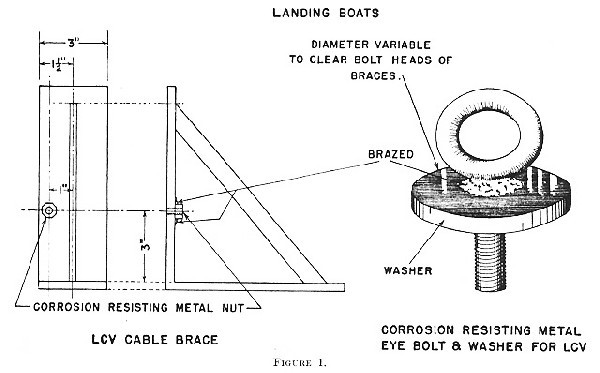
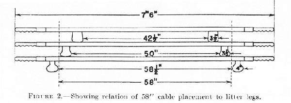
--107--
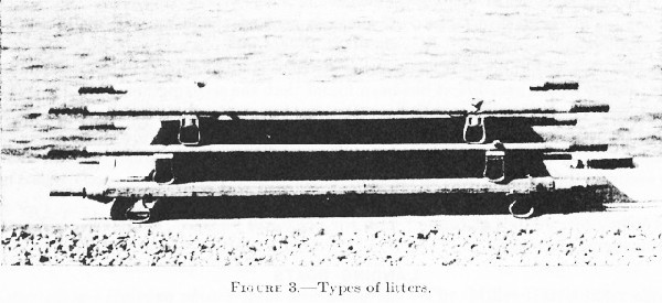
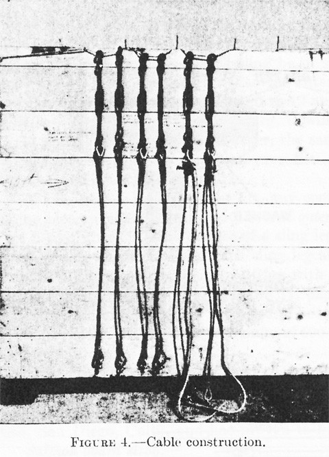
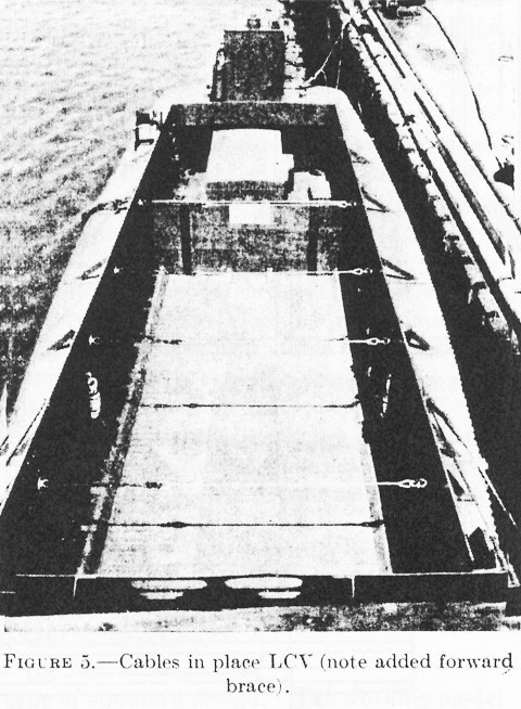
--108--
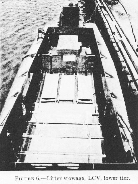
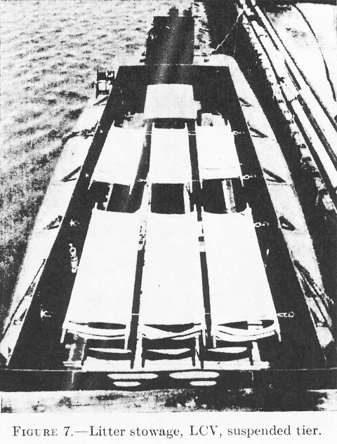
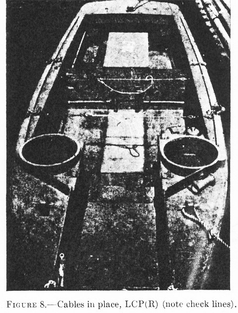
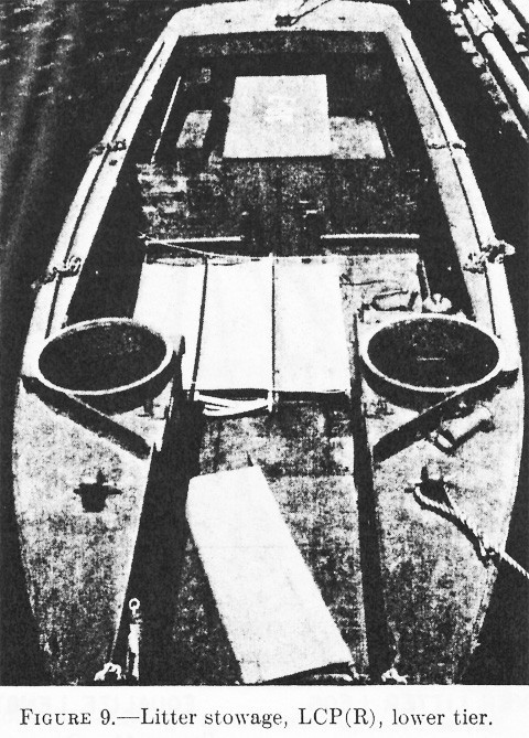
--109--
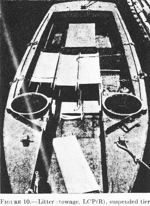
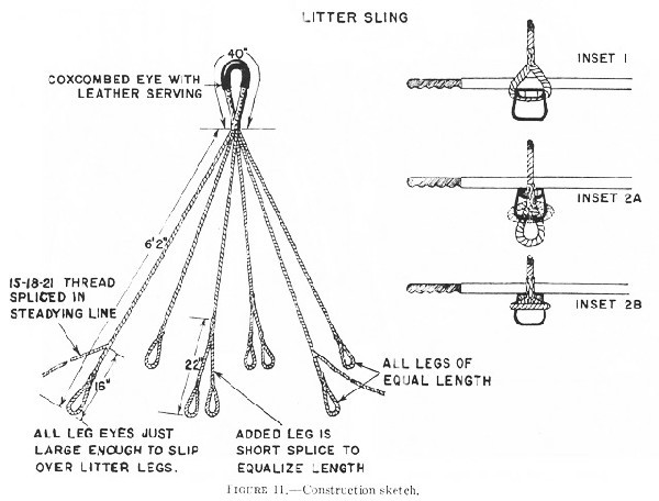
--110--
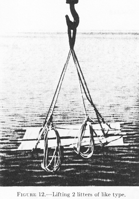
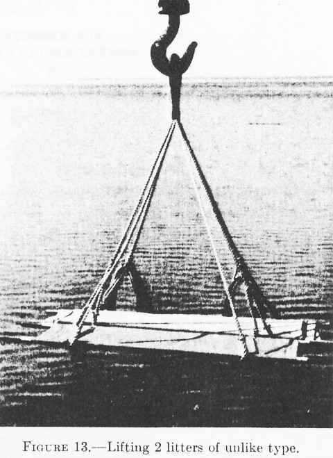
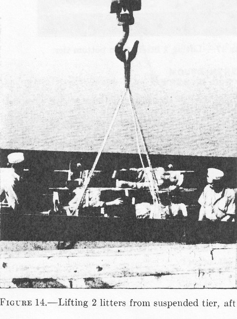
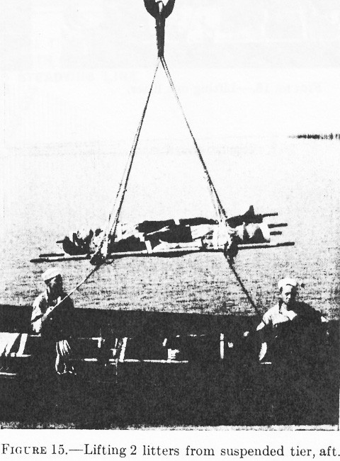
--111--
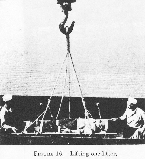
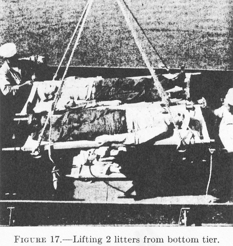
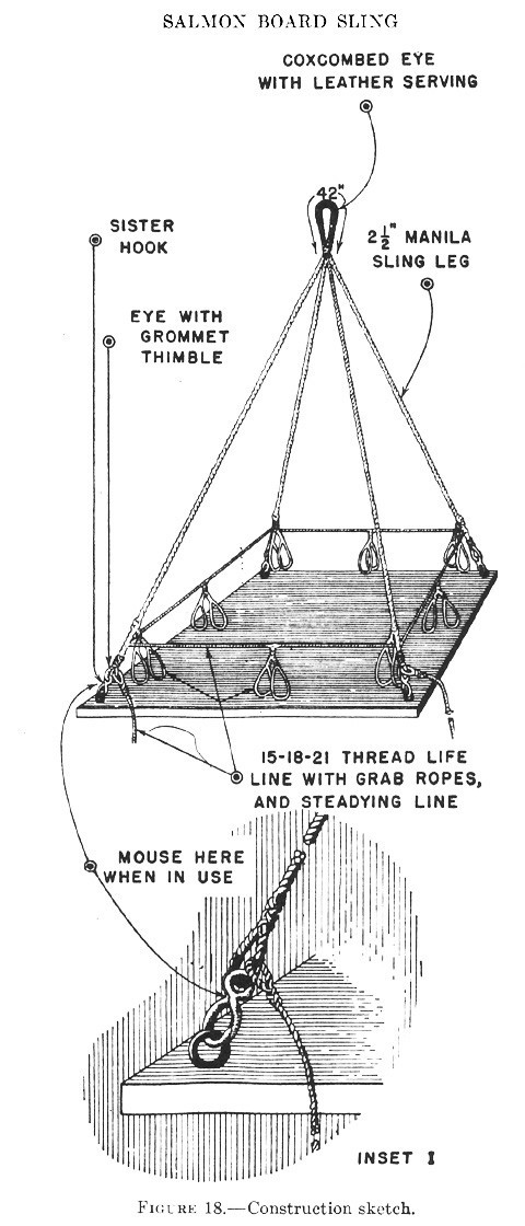
--113--
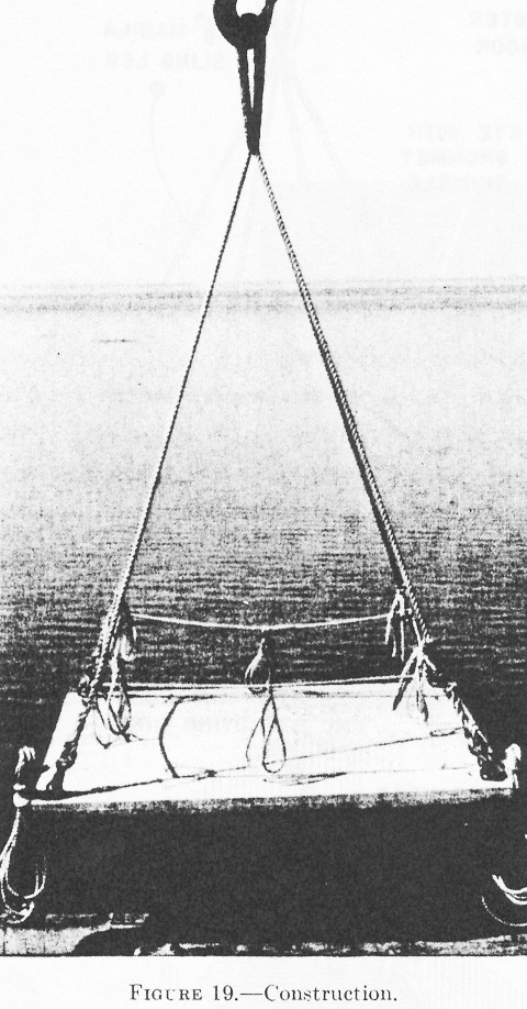
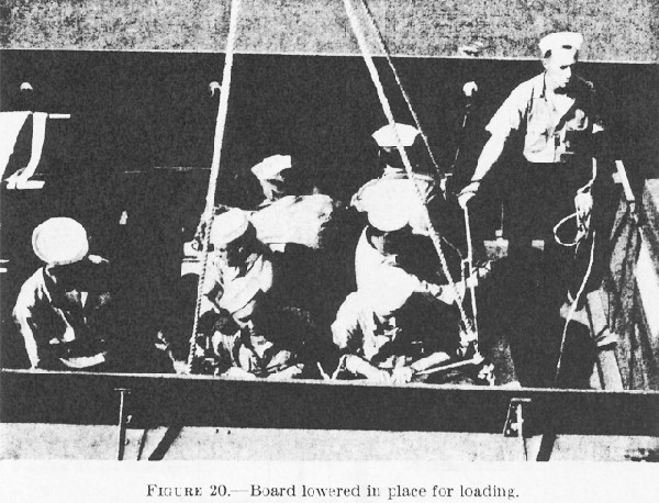
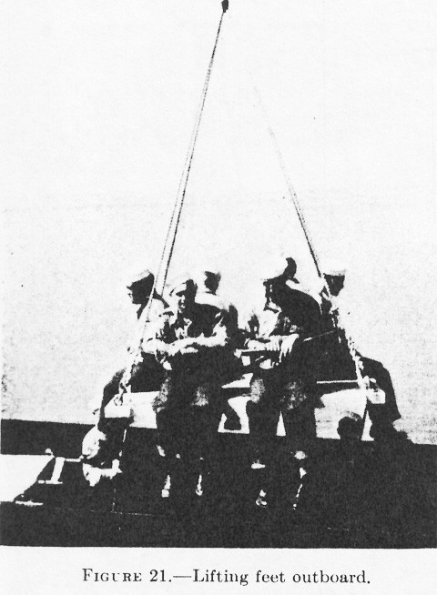
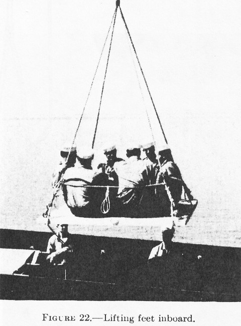
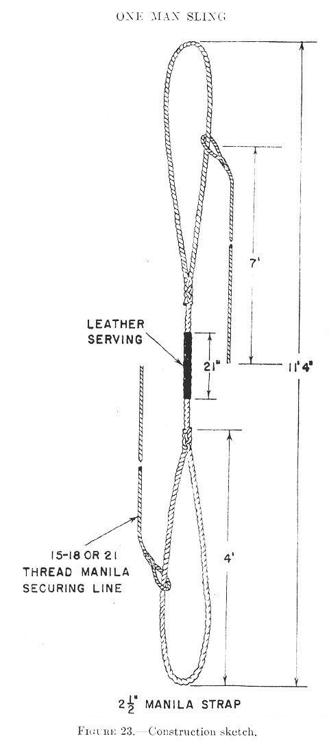
--116--
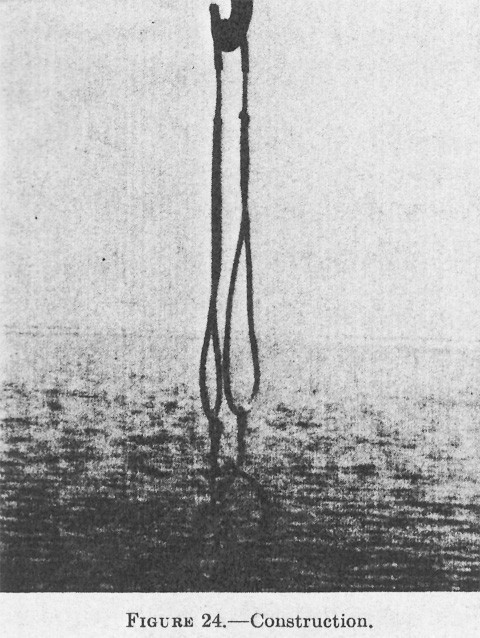
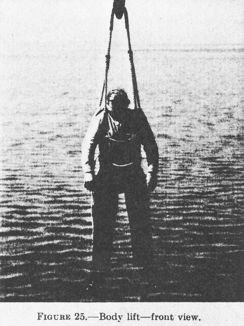
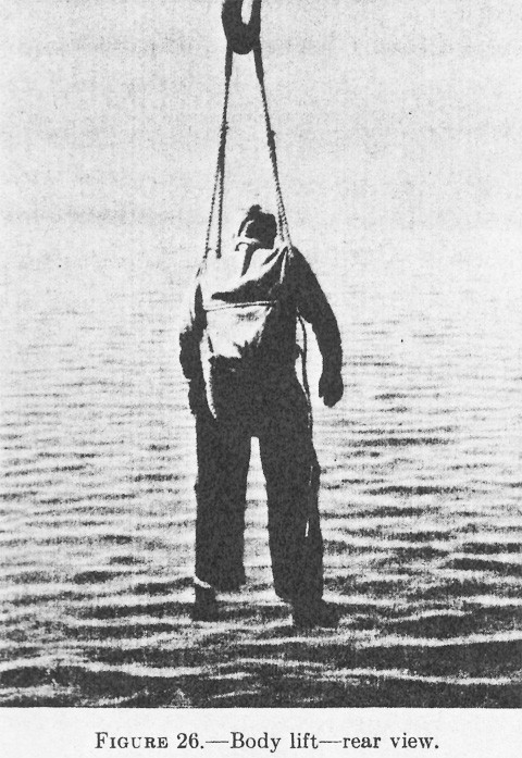
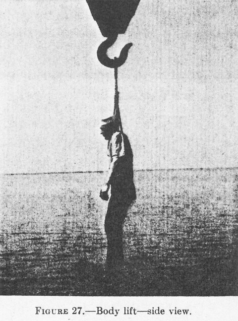
--117--
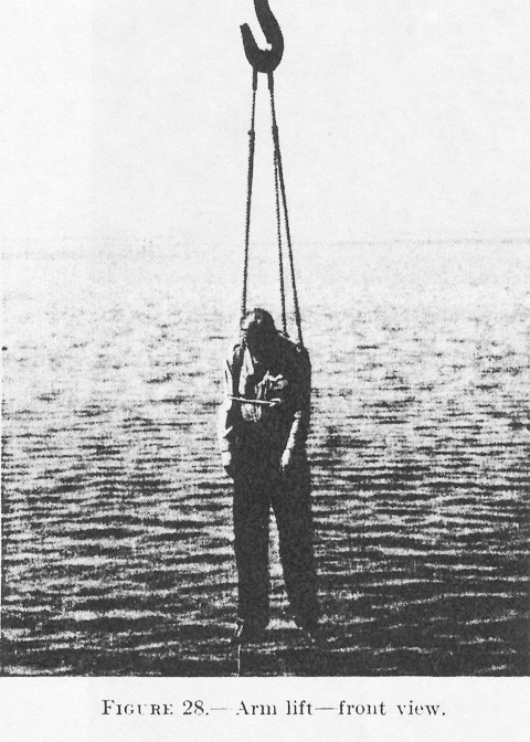
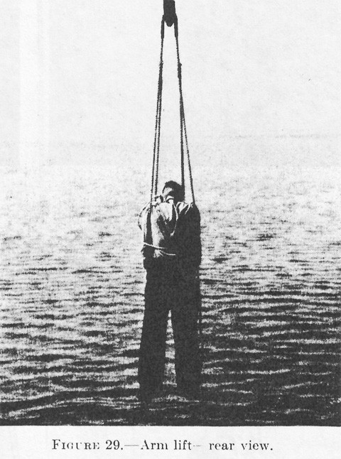
--118--
[END]
