The Navy Department Library
Japanese Radio Communications and Radio Intelligence CinCPOA 5-45
"Know Your Enemy!"
[Declassified] Confidential
1 January 1945
Japanese Radio Communications
and
Radio Intelligence
"Know your Enemy"!
CinCPac - CinCPOA Bulletin 5-45
IT IS PARTICULARLY REQUESTED THAT THIS ARTICLE BE BROUGHT TO THE ATTENTION OF ALL COMMUNICATION OFFICERS AND SIGNAL OFFICERS.
Japanese Radio Communications and Radio Intelligence
Introductory
This article on Japanese radio communications is based on captured documents, with some information added from interrogations of prisoners-of-war. It should he remembered, therefore, that the data given represents Japanese theory rather than practice, and that much of the information may now be outdated. Within these limitations, however, a fair picture may be drawn of Japanese Naval radio communications.
Information on Army communications is far less satisfactory. There is not enough material available for an over-all survey, and Army communications have therefore been treated chiefly in relation to the Navy.
General
Japanese communications in general comprise a complex, modern system, highly flexible and efficient. Older equipment is obsolete by American standards but ruggedly built. The newest enemy equipment compares favorably with our models. There is some evidence that the system is handicapped by a shortage of trained personnel, but an evident determination exists to make the best use of existing facilities.
A captured log of the Control Station of the Army Signal Office at SAIPAN gives an example of what Japanese communicators accomplish under the most adverse conditions:
"20 June 1944. Although there was a bombardment close to us, it did not affect our personnel or equipment. By the utmost effort in maintaining the lines, at 9 o'clock...all lines except the second were open and working well. (Comment: This refers to the control lines from the central station to the various transmitters on the island.) At 2220 all lines were severed by bombardment. Immediately set out to restore the lines....
"21 June. Although we worked to keep the lines operational since last night, the lines were cut in as many as ten places due to shells. At 0730 we restored the line; at 0950 all lines were restored; at 1500 they were severed again." (Comment: The document further indicates that on that day 18 despatches of 606 words were cleared to TOKYO.)
This same emphasis on keeping communication open in spite of all difficulties is reflected in repeated instructions for the dispersal and revetting of transmitters and the camouflaging of radio stations.
However, Japanese communications have their shortcomings, as indicated when the CVE Chuyo was sunk. The failures of ship-borne equipment at this time became the subject of a formal official study, compiled in February 1944 by the
--1--
Yokosuka Naval Communications School.
On 30 November 1943, the CVEs Zuiho, Chuyo, and Unyo, the CA Maya and four destroyers sortied from TRUK bound for YOKOSUKA. Just before midnight on 3 December, while the formation plowed northward through typhoon weather, the Chuyo was torpedoed by the U.S.S. Sailfish, but was able to proceed. Only the Maya received the stricken ship's report of the torpedoing over the ultra-high frequency circuit. Twenty minutes later, the Chuyo transmitted an amplifying message over the Combined Fleet command circuit which was received by the Maya and by the other carriers. The destroyers did not learn of the attack until 0200 (I) the next day, via the TOKYO broadcast. At 0500 the Chuyo was torpedoed again and was unable to make headway. Through faulty communications she lost contact with the formation, and was torpedoed a third time. The ship sank at 0848. (Comment: For a full story on the sinking of the Chuyo, see "Weekly Intelligence", Vol. 1, No. 5).
The official Japanese report concluded:
"Since the plan of communication and the communications command were not suitable, and since there was an error in judgment regarding the reports concerning the enemy submarine, and because the measures taken after the first torpedo attack were inadequate, the Chuyo received two more torpedo attacks and finally sank."
There is not enough definite information available on Japanese Army radio communications to attempt a systematic description. It is thought that radio plays a less important part than in Navy systems, since extensive land wire and cable facilities are available. However, numerous Army radio circuits are in use. SAIPAN, for example, maintained direct Army circuits with TOKYO, CHICHIJIMI, PAGAN, TRUK, RABAUL, GUAM, YAP, MENADO, MANILA and NAHA.
An interesting feature of Army communications is the friction which has been noted on several occasions when cooperation with the Navy has been necessary. In the MARIANAS, the Navy system was ordered for all joint Army-Navy communications, with considerable resultant hard feelings.
One typical incident was described in a captured Staff Diary of the SAIPAN-based Jap 31st Army, on 16 March (1944). The question here was whether the 8th Expeditionary Unit, scheduled to reinforce the enemy's Central Pacific Command, was to land at SAIPAN or TRUK. The issue was in doubt as late as the day before the Unit was supposed to land at SAIPAN - when it was ordered on to TRUK! The Army document complains that "the decision on the landing point...was a very complicated matter and many things were not clearly understood, because:
- Army orders, the relations between the Army and Navy, and the way of handling transport and convoy problems are very complicated.
- The 5th Base Force Signal Unit was responsible for communications. Not only did they make the wireless messages late, but they left out the Navy's serial number on the orders and made mistakes in distributing them. For example, although one message was identical with the message dated 3 March mentioned in 'H' above, the Navy
--2--
serial number was omitted when it was stamped 16 March; furthermore, the serial number on the 3 March order from Headquarters of the General Staff was also omitted; it was very difficult to compare these messages and the ones received previously. This is only a minor case but a very important one from the standpoint of a unified command...It is necessary to establish codes and signal sections for the Army's special use."
It may have been such an incident that led to an Army order that in case of a breakdown or emergency, the South Seas Government communications nets were to be used in preference to the Navy systems.
Navy Communications
Japanese Naval communications are under the general cognizance of the Minister of the Navy and the Chief of the Naval General Staff, which exercise control through the Communications Section of the Navy Department at TOKYO. Little is known of the functioning of this organization, but presumably it sets policies, standardizes procedures, and inspects and administers the entire Naval communications network.
The backbone of the system consists of the enemy's Communications Units, of which there are approximately 25. These units have no direct parallel in the U.S. Navy. Like other Jap shore-based Naval units, they are provided and maintained by the major Naval Districts in the Empire and in a few cases by Guard Districts. They are under the Minister of the Navy in regard to communications necessary to military administration, and under the Chief of the Naval General Staff in regard to communications necessary to tactical operations. Outside of Japan, their organization generally parallels that of the Base Forces, and presumably they are under the tactical command of the Base Force commanders.
Communications Units are divided into the regular Units, the "Specially Established" Units (activated in addition to the normal peacetime establishment), and Combined Communications Units (for radio intelligence). Communications Units and Specially Established Communications Units are shown on the accompanying tables, extracted from the Japanese Navy Administrative Orders (NAIREI). This organization is believed to be complete as of 1 June 1944. There has been no attempt to revise it according to events since that date. Combined Communications Units are not shown on these tables, since only the First is known to have existed, and this may have been wiped out on SAIPAN. The activation of further Combined Units is probable but not yet demonstrated.
No difference in function is known to exist between Communications Units and Specially Established Communications Units. Both types serve as communications centers for their areas, and are in general responsible for delivery of traffic within these areas. Both types have detachments, frequently three or four to a Unit and sometimes as many as five.
--3--
Communications Units
Taken from the Japanese Navy Administrative Orders (NAIREI) revised to 1 June 1944.
Notes:
- Specially Established Communications Units are marked with an asterisk (*).
- Unless specifically designated by a name or number, detachments of Communications Units are named according to their locations (e.g., SHIMUSHU Communications Unit, MATSUWA Detachment).
- Classifications are given as follows:
KO - Communications Command; code and voice signal, sending and receiving. OTSU - Primarily code signal dispatch. HEI - Primarily code signal reception. TEI - Primarily RDF. BO - Primarily RDF control. KI - Primarily Radio beacon installation.
| Assignment | Designation | Main Unit | Detachments | ||
|---|---|---|---|---|---|
| Location | Classification | Location | Classification | ||
| YOKOSUKA N.D. | TOKYO Naval Communications Unit | TOKYO | KO, HEI | FUNABABASHI TOTSUKA KANIGAYA |
OTSU OTSU HEI |
| YOKOSUKA Naval Communications Unit | YOKOSUKA | KO, HEI, BO | MUTSUAI HATSUSE SHIRAKATA HACHIJO OSHIMA |
OTSU HEI, TEI, BO TEI TEI KI |
|
| *OWADA Communications Unit | OWADA | KO, HEI, TEI, BO | |||
| *1st Communications Unit | To be decided by CinC Combined Fleet | KO, OTSU, HEI, TEI | |||
| *2nd Communications Unit | To be decided by CinC Combined Fleet | KO, OTSU, HEI, TEI | |||
| *3rd Communications Unit | PALAU, KOROR | KO, OTSU, HEI | 1st det.,PELELIU 2nd det.,AIRAI |
TEI OTSU |
|
--4--
| Assignment | Designation | Main Unit | Detachments | ||
|---|---|---|---|---|---|
| Location | Classification | Location | Classification | ||
| YOKOSUKA N.D. (cont.) | *4th Communications Unit | TRUK, DUBLON I. | KO, HEI | 1st det., DUBLON I. 2nd det., ULALU I. 3rd det., PONAPE 4th det., UMAN I. 5th det., MOEN I. |
OTSU, TEI, KO, OTSU, HEI OTSU OTSU |
| *5th Communications Unit | SAIPAN | KO, OTSU, HEI, TEI | |||
| *8th Communications Unit | RABAUL | KO, HEI, BO | 1st det., RABAUL 2nd det., RABAUL |
OTSU TEI |
|
| *SHIMUSHU Communications Unit | SHIMUSHU | KO, OTSU, HEI | PARAMUSHIRO MATSUWA |
TEI, BO TEI |
|
| KURE N.D. | KURE Naval Communications Unit | KURE | KO, HEI | SHOSAN MIYASAKI NAKAKUROSE KOCHI |
OTSU TEI HEI, BO TEI |
| *OSAKA Communications Unit | OSAKA | KO, HEI | MORIGUCHI det., OSAKA SHIONOMISAKI |
OTSU TEI |
|
| *10th Communications Unit | SINGAPORE | KO, HEI, BO | 1st det., SINGAPORE 2nd det., SINGAPORE 3rd det., SABANG 4th det., PENANG |
OTSU TEI TEI KO, OTSU, HEI, TEI |
|
| *25th Communications Unit | To be decided by CinC Combined Fleet | KO, OTSU, HEI, TEI | |||
--5--
| Assignment | Designation | Main Unit | Detachments | ||
|---|---|---|---|---|---|
| Location | Classification | Location | Classification | ||
| SASEBO N.D. | SASEBO Naval Communications Unit | SASEBO | KO, HEI | HARIO MAMBA HAKATA EI TANEGASHIMA |
OTSU HEI, TEI, BO TEI TEI TEI |
| *12th Communications Unit | At location of 13th Base Force | KO, HEI | 1st det. 2nd det. (both at location of 13th Base Force) |
OTSU TEI |
|
| *21st Communications Unit | SOERABAJA | KO, HEI, BO | 1st det., SOERABAJA 2nd det., SOERABAJA 3rd det., MALABAR 4th det., (to be decided by CinC Combined Flt. |
OTSU TEI OTSU TEI |
|
| *24th Communications Unit | AMBOINA | KO, HEI, BO | 1st det. 2nd det. (both to be decided by CinC Combined Fleet) |
OTSU TEI |
|
| *85th Communications Unit | To be decided by CinC Combined Flt. | KO, HEI, BO | 1st det. 2nd det. 3rd det. (all to be decided by CinC Combined Fleet) |
OTSU TEI KO, OTSU HEI, TEI |
|
| *RASHIN Communications Unit | CHOSEN | KO, HEI, BO | MEIKO DO det., RASHIN KAIMON EIKO |
OTSU TEI |
|
| MAIZURU N. D. | MAIZURU Naval Communications Unit | MAIZURU | KO, HEI, BO | SHIRAKU UESUGI SHIBATA NAKAHOJO |
HEI, BO OTSU TEI TEI |
--6--
| Assignment | Designation | Main Unit | Detachments | ||
|---|---|---|---|---|---|
| Location | Classification | Location | Classification | ||
| MAIZURU N. D. | *31st Communications Unit | MANILA | KO, HEI, BO | 1st det., MANILA 2nd det., MANILA |
OTSU TEI |
| OMINATO Guard District | OMINATO Naval Communications Unit | OMINATO | KO, HEI, BO | CHIKAGAWA SEKINE NEMURO WAKKANAI HENASHI |
OTSU TEI TEI, KI HEI, TEI, KO, OTSU TEI |
| CHINKAI Guard District | CHINKAI Naval Communications Unit | CHINKAI | KO, HEI | JONAN RAKUTO GYUTO HEIKAI |
OTSU TEI TEI TEI |
| TAKAO Guard District | TAKAO Naval Communications Unit | BAKO | KO, HEI | SAIEN TESSEMBI |
OTSU TEI |
| TAKAO | KO, HEI | HOZAN GARAMBI SHINJO |
OTSU TEI TEI |
||
--7--
In addition to the enemy's Naval Communications Units and their detachments, ships and shore activities not directly served by Communications Units participate in the communications network.
To tie together Communications Units, ships, and shore stations, three main types of radio service are provided: broadcast, ship-shore and point-to-point.
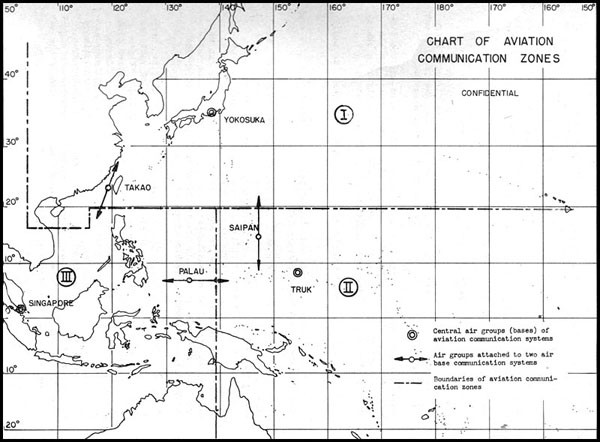
Broadcast zones are divided into the Central Broadcast Communications Zone, which includes all areas, with TOKYO as the sending station, and the so-called Local Broadcast Communication Zones, shown in the attached Chart No. 1. This chart is taken from the 1943 Communications Regulations, and has been outdated by subsequent Allied campaigns, but it serves at least to illustrate the general system used.
In general, main radio ships and stations guard central broadcasts, as well as the local broadcast of their particular zones. Minor ships and stations guard local broadcasts or point-to-point circuits according to specific instructions.
Central broadcasts are organized as follows:
Central Broadcast #1 is guarded by flagships of Divisions and Fleets attached to the Combined Fleet, and by Communications Units. It carries despatches concerning operations, and important despatches originating centrally.
Central Broadcast #2 is guarded by main radio ships and stations, except aircraft.
Central Broadcast #4 is guarded principally by submarines.
Local broadcasts serve to deliver traffic to ships and stations within particular zones, and are closely dovetailed with the ship-shore circuits. A ship with limited reception facilities may guard either the local zone broadcast or the frequency used to call ships in that area, according to a special arrangement. For purposes of convenience or security, a ship may be served by a communication zone in which it is not actually located. As far as ships are concerned, the geographical boundaries shown in Chart No. 1 are merely indications, and not hard and fast rules.
Ship-shore communications systems are likewise divided into a central system, with the main unit at TOKYO, and local systems. Local ship-shore systems are guarded either in conjunction with, or alternately to, the local broadcasts. According to Jap Communications Regulations, "If their positions or movements make it necessary, ships may be attached to a local ship-shore communication system other than the nearest one, or may be attached to two or more local ship-shore communication systems at the same time." These ship-shore systems use principally long wave, but short wave may be used as necessary. Shore stations other than communication units, as well as ships, may communicate over these circuits.
--8--
ADAPTED FROM THE 1943 EDITION OF JAPANESE NAVY COMMUNICATIONS REGULATIONS CHART
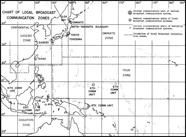
CHART OF LOCAL BROADCAST COMMUNICATIONS ZONES
--9--
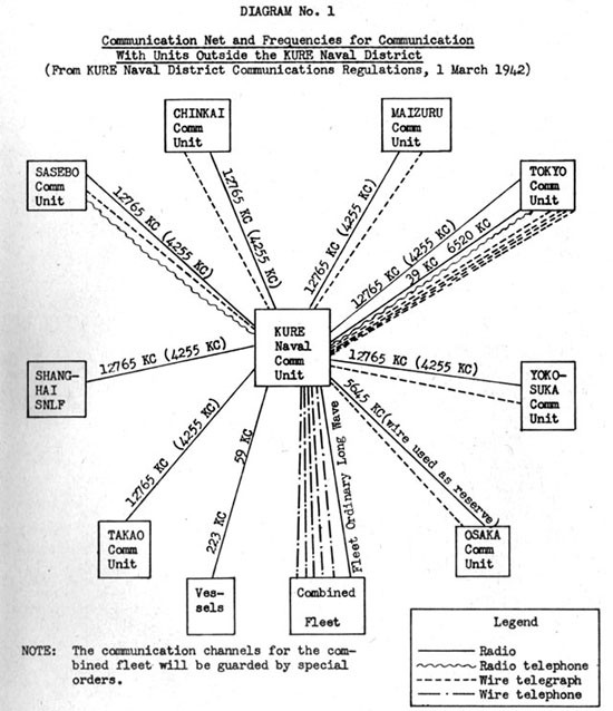
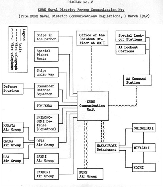
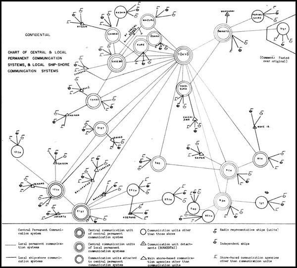
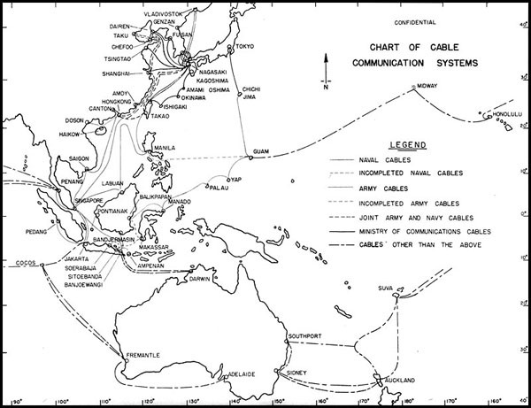
The permanent - or point-to-point - communication network is also divided into general and local systems, as show in Chart No. 2. The general system provides point-to-point service between TOKYO and the major Communications Units, while the local systems serve to link each Communications Unit with neighboring Units and detachments. A good illustration of the network built up around each Unit is given in Diagram No. 1, showing the circuits between KURE and neighboring Units.
Aircraft communications, plane-to-plane and ground-to-plane, have their own circuits and frequencies, tied into the regular communications network through the Air Groups and Air Bases.
Radio communications are supplemented to a considerable extent by wire transmissions, particularly in the Empire. In addition to the cable facilities shown in Chart No. 4, a telephone and telegraph network connects all important bases in Japan, with connections to fleet buoys at KURE, MIKAWA BAY, KISARAZU, and OMINATO. A teletype system connects TOKYO with SASEBO, KURE, YOKOSUKA and MAIZURU. It is not known to what extent actual despatches are passed over these circuits, but all communications regulations which have been examined call for the use of wire instead of radio whenever feasible.
--10--
--11--
--12--
Outline Chart of Host Common Frequencies Used by the Japanese Army and Navy Radio Sets
| Transportation | Type of Radio (Jap name) | Frequency ranges (megacycles) | Power (KW) | Maximum range (kilometers) | Use | Miscellaneous remarks |
|---|---|---|---|---|---|---|
| Air-borne | Type 1 Air Mk III (W/T) | 30-45 mc/s | 5 KW | 50 miles at 10,000 feet | Command set | Has Code and Voice emission & reception. Receiver is a superhet. Used in Jap ZEKE, OSCAR, and HAMP |
| Air-borne | Type 96 Air Mk I Radio | 7.5-10.0 mc/s | 30 watts (output) | (code) 600 nautical miles (voice) 150 | Air-ground comm. | Has code and voice emission and reception. 3 tube receiver. Used in single seater and 2 seater planes. Chiefly in submarine-borne aircraft. |
| Non-portable | Type 92 Mk III (long wave transmitter) | 0.1-1.0 mc/s | 1 KW | 500 to 12,000 miles | Fixed station work | Has Code emission only. Transmitter a Hartley oscillator. Electrical design poor throughout. No weather proofing or fungus protection noticeable. |
| Non-portable | Type 95 Mk IV, Modification 1, shortwave transmitter | 3.7-18.2 mc/s | 500 W | 300--12,000 miles | Fixed station work | 5 tube transmitter. Only code emission. Has separate 2.5 KW power supply. Well constructed and electrical design is good. |
| Field (mobile) | Type TU shortwave portable transmitter, Modification 3 | 1.5-18.0 mc/s | 200 W | 1,000 miles | Div. HQ ft larger unit nets | 3 tube transmitter. Only code emission. Gasoline generator is power source. Well designed mechanically and electrically. No fungus or weather protection. |
| Field (pack) | Type 97 Light Radio Set (Jap "Walkie-Talkie") | 22.7-29.5 mc/s | 300-400 Milliwatts | Under 2 miles | Small infantry units; air-ground liaison also | Receiver simple; has regenerative detectorself quenched. Batteries or hand generator are power source. Attempt made at waterproofing. Still not completely moisture proof. Used by landing parties. |
| Vehicular (cars & trucks) | TTK Model 147 Mobile Radio Set "B" | 1.5-5.5 mc/s | 30 or 5 Watts | 25 miles on high power; 5 miles on low power | Inter-mech. unit comm. | Antenna is "whip" type. Receiver is superhet. Code and voice emission. A dynamotor is power source. Good mechanical and electrical design. |
| Vehicular (tanks, cars, trucks) | Type TM Model 305 Mobile Radio Set | 19.6-30.6 mc/s | 30-50 W | 25 miles | Inter-mech. unit comm. | Receiver is superhet. Code and voice transmission. Dynamotor is power source. Excellent mechanical design and construction. Comparable to American gear of recent design. |
| Field (mobile) | Type 94 Mk I (W/T) Radio Transmitter | 0.14-15.0 mc/s | 275 W | 75 miles | Regimental net | Code and voice emission. Rugged set. No evidence of anti-moisture, fungus measures. Difficult to change frequencies. |
| Navigational Aid (air-borne) | Type 1 Air Mk III Direction Finder and Homing Device | 170-460 kcs (guiding.)450-1200 kcs (broadcast) | None (not a transm) | Direction finding & homing | * See note below | |
| Navigational Aid (fixed) | Type 93 Close range Radio Direction Finder, Modification 1 | 2.2-25.7 mc/s | None (not a transm) | Plane locating | Superhet. Generally of fair design but shielding between the stages is good. No evidence of waterproofing. | |
| Field (Navigational Aid) | Type 94 Model 1 Portable Direction Finder | 0.1-2.0 mc/s | None (not a transm) | D/F'ing on land stations & planes | Old-fashioned receiver, of good mechanical construction. Electrical design is good with exception of large number of tuning controls. No anti-fungus, or anti-humidity measures. |
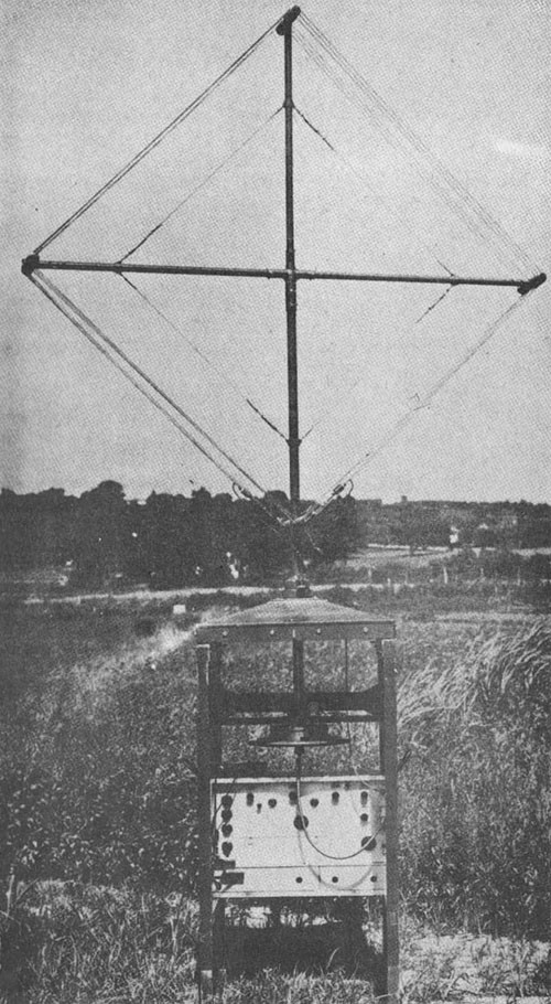
* Course-indicator does not operate over great distances, has many defects. Appears that Japanese use this receiver in fighter aircraft to direct them to a rendezvous with enemy planes. Gear identical with that designed by Fairchild Aerial Camera Company. The antenna is a single rotatable loop with sense antenna.
--13--
Japanese Radio Intelligence and Counter-Intelligence
Data on Japanese radio intelligence is fragmentary, although considerable information is available on the Navy R. I. set-up, particularly as it existed in the MARSHALLS and the MARIANAS prior to Allied landings.
The Jap Army and Foreign Office are known to maintain radio intelligence activities, although organizational details are lacking. Information is apparently exchanged between the Army, Navy, and Foreign Office, and documents reveal the high importance attached by the enemy to data derived from this source.
The Japanese conception of radio intelligence is illustrated by the following quotation from the 6th Communication Unit Secret Order No. 1, dated 15 January 1943:
"The designation of Radio Intelligence in these regulations is a general term for attacks on the communications and operations of enemy communications. It includes the interception of enemy messages, RDF and its control, searching for enemy messages, the receiving and transmitting of intelligence, the treatment of related wireless messages, interference, deception messages and the exchange of deception messages."
It appears that Japanese Navy radio intelligence activity is carried out by special sections attached to certain regular Communications Units, as well as by certain special semi-independent outfits. RDF activity is extremely widespread, and is carried on by all regular Communications Units, and on occasion by ships and shore stations independently. Analysis of traffic load and call signs, and cryptanalysis, are apparently restricted in general to the regular RI units.
Naval RI activity is apparently centered in the Radio Intelligence Section of the Owada Communication Unit. According to a seaman 2/c, who was attached to the training section there in May 1944, the organization consisted of about 500 men, and was considered highly secret and very important. This prisoner, who was born and educated in the HAWAIIAN Islands, was selected for this work because of his knowledge of English, and was trained for about six weeks in radio telephone procedure, foreign broadcast interception, and translation.
Next in importance to the Owada Communications Unit was the 1st Combined Communications Unit, which was at one time located at RABAUL but moved to SAIPAN prior to the American attack. We have recovered a document prepared by this Unit in May, 1944 entitled "An Outline of the Enforcement of the Central Pacific Area Communications Intelligence." This document defines the Unit's mission thus:
"In the present war situation, what is expected of the communication intelligence at SAIPAN is that we shall have prior intelligence of enemy offensive operations from the east or southeast against the MARIANAS, the Eastern CAROLINES, or even JAPAN, and from the southeast against Northern NEW GUINEA area and even the PHILIPPINES."
--14--
Attention was to be focused on the movements of surface vessels, submarines, and patrol planes, in that order of priority, with the activities of submarines and planes to be studied particularly in their relation to the movements of Task Forces. The document contains the following statement of policy:
"Investigation and study continue over a long period of time and are minute and continuous... in carrying on this daily intelligence operation, it is necessary not to overlook any minute indication concerning intelligence of movements of enemy Task Forces."
There has also been recovered a table of allotment of RI personnel of the Central Pacific Area Fleet, dated 13 May 1944. The 1st Combined Communications Unit is not mentioned. While it is possible that this Unit was attached to the 5th Communications Unit, and that its complement is included, it appears more likely that it was in addition to these figures. A total of twelve officers and 215 men were attached for RI duties to the following Units:
| Officers | Men | ||
|---|---|---|---|
| 5th Comm Unit | 4 | 91 | |
| 4th Comm Unit | 5 | 75 | |
| 6th Comm Unit, 3rd Det. | 1 | 25 | |
| 6th Comm Unit, 1st Det. | 1 | 13 | |
| 3rd Comm Unit | 1 | 11 | |
| 12 | 215 |
Prior to our invasion of the MARSHALLS, KWAJALEIN served as a strategic center for Japanese radio interception. As of 15 January 1943, the Radio Intelligence Section of the 6th Communications Unit consisted of about forty-five officers and men. The principal effort was directed toward RDF and the interception of long and medium length wave transmissions for U.S. vessels and aircraft.
Little is known of the remainder of the Japanese Navy RI organization. Other Combined Communications Units may have been organized, but information is lacking. Intercept stations have been reported at SHANGHAI and SINGAPORE, and RI Units are said to be attached to all Fleet flagships and Fleet headquarters. In November, 1943 the CVE Zuiho had aboard two members of the 6th Comm Unit RI Section for the trip from TRUK to the EMPIRE, but their efforts in the interception of U.S. submarine transmissions did not prevent the sinking of the Chuyo in company. On 25 April 1944, the Opord for a transportation run to MERIR, SONSOROL and TOBI specified that the Yubari, acting as flagship for the convoy, should use her surplus receiving facilities to intercept U.S. submarine communications.
The Yubari, shepherding a large convoy, was reported sunk on 27 April near SONSOROL by the USS Bluegill (on the first attack of this sub's first war patrol), indicating the ineffectiveness of these precautions. Bad weather further handicapped the enemy in this case, just as at the time of the Chuyo's loss.
--15--
Taken From the 1943 Edition of Japanese Navy Communications Regulations Chart 2
--16--
Some hint of the methods employed by Japanese radio intelligence is found in the following quotation from an official Reference Manual on Communications issued in January 1944:
"The organization of Radio Intelligence within the Navy Department:
- The OWADA communications unit, as well as the stations at RABAUL, SINGAPORE and SHANGHAI, maintain a listening radio watch on all frequency bands.
Method of monitoring:
Receive by typewriter. Decode messages. A phonograph recording is made. Also recorded on oscillograph photos. The latter offers a method of determining the transmitting ships or stations by means of their Morse spacing.
Receive by longhand. In this fashion, not only are the enemy's communications intercepted but his transmission peculiarities are discovered. Moreover, our own communications are monitored; the bad features are noted and those concerned informed accordingly. Example: During the ATTU campaign, the Northern Force was constantly engaged in communications. It was then pointed out from Central Hq. that there was too much radio traffic. At that time, the operational force maintained radio silence while the rear echelon troops of the Northern Forces sent dummy communications.
- Direction Finding.
All Navy communication units. Low freq. - High freq. Unified control.
- The RI Units which are attached to all fleet flagships and fleet headquarters intercept all enemy radio messages relating to operations and movements.
Receive by typewriter and in longhand."
A high-ranking Japanese meteorologist POW reports that in addition to the regular radio intelligence organizations, the Japanese have about 300 Army and 150 Navy cryptanalysts at work breaking Allied weather codes. This unit was established at the outset of the CHINA incident, and was recently enjoying considerable success in reading Allied weather reports from SIBERIA, ALEUTIANS-ALASKA, and the Southwest, particularly AUSTRALIA. (Comment: For further data on Jap meteorological practices, see "Weekly Intelligence", Vol. 1, No. 18).
The degree of success enjoyed by Japanese radio intelligence is difficult to gauge. Numerous captured intelligence reports indicate, however, that the Japs attach considerable significance to their findings, particularly with regard to RDF and the analysis of traffic volume. A few excerpts from captured
--17--
reports serve to indicate their general tenor:
(From an intelligence report of the 14th Division, dated 10 July 1944)
"NEW GUINEA Area
1. The number of vessels assessed to be in the NEW GUINEA Area on the 5th was 56, a reduction of 46 ships as compared to the 3rd, and of 16 ships as compared with the 4th. The vessels assessed to be at the principal bases were as follows:
| MORESBY | - | 37 ships | (increase of 17 over the 4th) |
| GOODENOUGH | - | 5 ships | (decrease of 12 from the 4th) |
| ADMIRALTY | - | 11 ships | (decrease of 8 from the 4th) |
Further it is necessary to pay heed to the fact that there have been urgent messages all day between MORESBY and ADMIRALTY, and that the vessels at ADMIRALTY are being gradually reduced in number."
(From a First Air Fleet intelligence report on enemy movements during March 1944).
"Although details regarding the Northeast Australia area are not known, it is estimated that landing operations will not begin from this area in the immediate future. A conspicuous point recently is that there has been a marked increase in the appearance of call signs for air and transport bases in occupied areas, and it is thought that the construction of air and supply bases is being rushed.
Patrol plane units (in the MARSHALLS) have been appearing in greater number since the middle of the month, and it is observed that patrol plane complements are gradually being filled. Since the end of the month, the movement of aircraft to the MARSHALLS has become gradually more active.
During March many RDF fixes were obtained on Naval vessels in Hawaiian waters, and the movement of transports and naval vessels in that area seemed very active.
Recently, while the enemy was operating in the South, intensified communication among those under the command of the CinC SoW Pacific Fleet was seen usually to precede the operation by six days. These developments may be preliminaries which indicate the communication of orders, etc., relating to operations six days hence.
Since the 25th radio messages concerning the Eastern NEW GUINEA Area Army were sent frequently addressed to four ships and stations, and at the same time dispatches from WASHINGTON, which were numerous, decreased in volume after the 25th and now amount to one or two a day.
--18--
Adapted From the 1943 Edition of Japanese Navy Communications Regulations Chart 3
--19--
"Important despatches, among messages issued from MORESBY on the 27th, were broadcast from GUADALCANAL addressed to three powerful ships and stations, these indicating the movements of strong forces on the North coast of NEW GUINEA. These forces are deemed to be the ones which subsequently attack PALAU. Many RDF fixes have been obtained on naval vessels in the area to the east of NEW GUINEA, and progressively intensified operations in the above area will probably continue."
(From an undated Battle Lessons Report)
"Signs of imminent landings which appear in communications:
In order to plan a landing operation and to concentrate strength at an advance base from two weeks to a month beforehand, the (American) fleet takes vigorous action and repeatedly sends out urgent messages.
Before attempting a landing, they enforce and revise calls and the dispatching code. At the same time, they adopt a common system for the radio broadcast net. In short, there is a high probability of a landing directly after active communications have abruptly ceased.
Aircraft use the ordinary telephone for contact among themselves and with their bases."
Enemy dissatisfaction in his radio intelligence was noted in a 31st Army Staff Intelligence report dated January 1944:
"As a type of electronic offensive in occupying isolated islands, they (the Americans) increase the effectiveness of surprise attacks after making ineffective the radio of the said island and frustrate our counter-measures. When our radios did not function at all as expected at the time of recent enemy landing operations, we must not come to the hasty conclusion that it was enemy interference. However, as we plan for management of communications between isolated islands hereafter it is necessary to study new technical methods devised by the enemy, and corresponding counter-measures."
"There are continued indications that the enemy is attempting to carry out entire operations more successfully with an active use of radio as a tactical weapon. That is to say, by using a special radio transmitting ship, false signals are transmitted, according to a fixed plan, which ring true from the standpoint of time and sector. In this way, an impression of a powerful enemy force is created; then, while we are being diverted, the real enemy force, maintaining strict radio silence and concealing its plans, carries out its movements in another area, and so confuses our signal intelligence. We must strengthen our signal intelligence net, therefore, and give thought to the problem of how we may read the enemy's moves in advance."
--20--
Japanese radio counter-intelligence measures involve the enforcement of radio security, jamming, and radio deception.
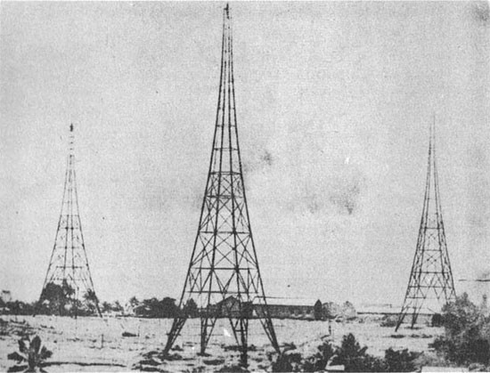
A number of documents have illustrated the increasing Japanese emphasis on radio security. Probably the most authoritative statement yet captured is found in a security manual issued by the First Combined Communications Unit on 15 August 1943, based on a study of both U.S. and Japanese radio traffic. This manual places great emphasis on the security of call signs, recommending frequent change of calls, encipherment of calls, the use of collective and general calls, and the changing of transmitter characteristics at the same time that call signs are changed. It further recommends the use of frequencies and power which will not reach the enemy, and the use by ships of shore-based transmitting facilities whenever possible.
--21--
Some idea of Japanese strategy for radio deception and jamming may be gained from "Navy Rules for Deception Messages and Jamming", a portion of which is quoted below. In this document a "KO" deception message is one in which the Japanese imitate Allied communications, and an "OTSU" deception message is one in which they imitate features of their own communications system.
"NAVY RULES FOR DECEPTION MESSAGES AND JAMMING
NAVY MINISTRY SECRET PUBLICATION #300
4 Nov. 1941
Deception Messages
Article 7. KO deception messages shall be used in the following situations:
- When an enemy code has been obtained.
- Compose the required message in the enemy code and transmit with the names of the necessary originator and receiver. (Method A)
- Depending on the contents of the intercepted enemy message, compose and transmit another, changing a part of the original text, or its number, time of origin, or the originator's and receiver's name. (Method B)
- When part or all of the call, originator's and receiver's name has been learned.
- Send, changing only the heading, time of origin, etc., of the intercepted enemy encoded dispatch. (Method C)
- Divide and transpose an intercepted enemy encoded text, or transpose a portion into another encoded text, in either case, adding elements from Method D.
- Compose and transmit the text of a deception message, employing plain language. (Method E)
- Carry on deception communication with the enemy by means of service messages. (Method F)
- When the code, call, and originator's and receiver's names are known.
- Change the call, and the originator's and receiver's names on the intercepted message and transmit. (Method G)
- Change all or part of the calls in the encoded text of the intercepted message and transmit. (Method H)
- Transmit the intercepted message after several days (weeks, months). (Method I)
--22--
Article 8. OTSU deception messages shall be used in the following situations; when necessary, use them in conjunction with deceptive maneuvers.
- When an encoded or meaningless text is used.
- Encode the message to be sent, using a superseded code book identical in form with the current code book. (Method M)
- Encode the necessary message, using the current code book. (Method N)
- Use a meaningless text whose form is identical with that of an encoded text derived from the current code book. (Method O)
- When plain language and abbreviations are used.
Compose a message which befits the circumstances, using the form of an actual communication. (Method P)
Article 9. The rules for deception message distinction must always be applied to OTSU deception messages.
Article 10. The Imperial General Headquarters (Naval General Staff) plans and directs, for the most part, the use of the following deception messages:
- KO deception messages using captured codes.
- Strategic KO deception messages.
- Strategic OTSU deception messages.
Article 11. The supreme commander of each fleet, naval station, special guard district, and secondary naval base force will principally decide and execute matters concerning the following deception messages:
- In tactical areas, KO deception messages utilizing simple enemy codes.
- In tactical areas, KO deception messages to be used against the enemy's meteorological communications.
- Tactical KO deception messages using plain language.
- KO deception messages based upon an exchange of service messages.
- Tactical OTSU deception messages.
JAMMING
Article 20. Jamming shall be conducted only after its hindrance to enemy communication has been weighed against the advantage to be gained by our using
--23--
Adapted From the 1943 Edition of Japanese Navy Communications Regulations Chart 4
--24--
the enemy's communications and against the enemy's use of our wave length.
Article 21. Except for instances when it is urgently necessary to the operation at hand, it is an established principle that notice be sent to all parties concerned before the jamming is started.
Article 22. The Imperial General Staff (Naval General Staff) generally plans and directs the jamming of strategic enemy communications; but when necessary, it will plan and direct the jamming of tactical communications, too.
Article 23. Jamming by all fleets, naval stations, special guard districts, and secondary naval base forces shall be prescribed and conducted by their respective supreme commanders, when it concerns principally tactical matters and enemy communication related to operations in their area."
Japanese Radio Equipment
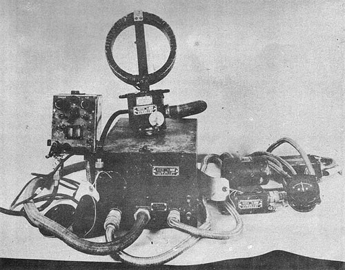
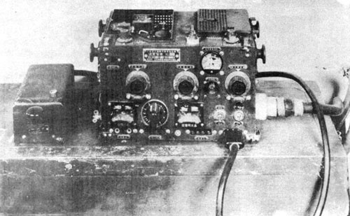
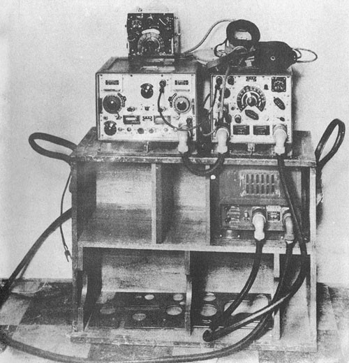
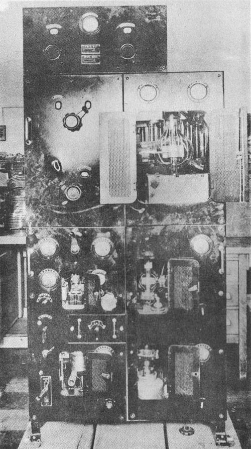
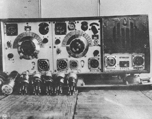
Japanese radio materiel has varied from poor to excellent. All the early equipment captured has shown both poor design and construction and appeared to be several years behind American standards. The last few pieces of equipment to fall into our hands have shown marked improvement in these respects.
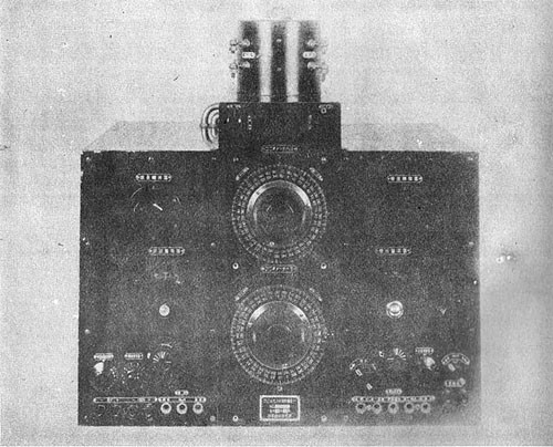
Some materiel manufactured late in 1943--for example the air-borne Type 3 Air Mk. 1, and two vehicular sets TTK Model 147B and TM Model 305C--have the latest features of electrical design and show real excellence of construction. Their main features are comparable to the latest American models.
In outward appearances, Japanese radios are neat and modern-looking. They are of light weight, require a minimum of space and are easy to transport. Many are obviously copied from leading types manufactured by the United States, Britain or Germany.
The enemy has taken considerable pains to build radios which will withstand field conditions without need of servicing. The Naval Research Laboratory in Washington, commenting on a portable radio transmitter and receiver, states: "...this set is very well constructed and its ruggedness, simplicity, and general excellence of design is worthy of note." However, the article goes on to say, "...no fungus protection or weatherproofing is detectable." This technical manual declares that the majority of Japanese radios studied are similarly lacking in weatherproofing of any kind. Japanese radios are apparently not built to withstand fungus or extreme humidity.
Another shortcoming of Japanese radios is the fact that they are in general extremely difficult to service. This feature is perhaps a by-product of the haste with which Japanese engineers have copied features from foreign-built radios. In some instances, entire back and front sections of the transmitter or receiver must be completely removed in order to repair one damaged part. Lack of trained personnel has also apparently adversely affected Japanese radio maintenance. The YOKOSUKA Air Group stated in December 1943 that only 300 radio maintenance men were available, whereas the Navy needed some 6,000.
--25--
The radio tubes manufactured by JAPAN at the present time are by and large inferior to our own. Japanese have in the past copied our tube designs and are continuing to do so.
As mentioned above, Japanese radio and electrical engineers have made remarkable strides recently towards the improvement of their apparatus. Generally speaking, Japanese radio sets have lagged several years behind those of America, Britain, and Germany. However, since the outbreak of war, JAPAN has captured large quantities of American radio gear and has made good use of its design. It should be remembered that the efficiency of any radio equipment varies widely with such factors as the skill of the operator, the frequency used, atmospheric conditions, sun-spot activity, and countless others. From the materiel point of view, however, it seems probable that JAPAN is approaching reasonably closely the quality of American equipment.
--26--
--27--
--28--
--29--
--30--
--31--
--32--
--33--
[END]
