
The Navy Department Library
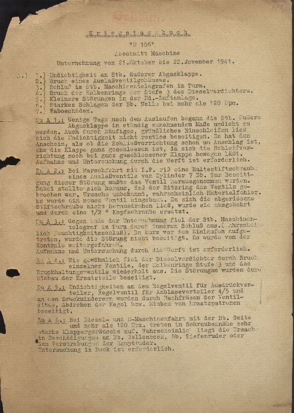
U-606 Engineering Section War Diary
The following Engineering Section War Diary reports are from U-106 and cover the period 21 0ctober 1941 to 29 July 1942, when the submarine was commanded by Captain Lieutenant Hermann Rasch. At that time, U-106, like U-505, was based at the German Navy Yard Lorient, France, and was part of the 2nd [ U-boat] Flotilla, composed of approximately 91 submarines. Since these reports were captured on U-505, presumably they were reproduced and distributed among submarines in the flotilla. Experiences and lessons learned by individual submarines would thus be shared among vessels in the flotilla.
-2-
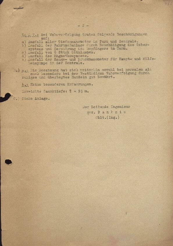
Additionally A7.: By depth charge action the following damage:
a) Failure of all depth meters in the tower and central control room.
b) Failure of the log system through damage to the transmitter systems and destruction of the receivers in the tower.
c) Failure of 6 electric lamps.
d) Failure of magnetic compass.
e) Failure of the vacuum and pressure meters for main-prime pump in the control room.
B.) a.: The crew has continued to function normally as expected and especially after 7 hours of depth charging through which considerable action was well taken.
b.: No further experiences.
Attainable diving depth T= 93 m.
C.) [See ?] Plans
Chief Engineer
Panknin
Lieutenant ( Engineer)
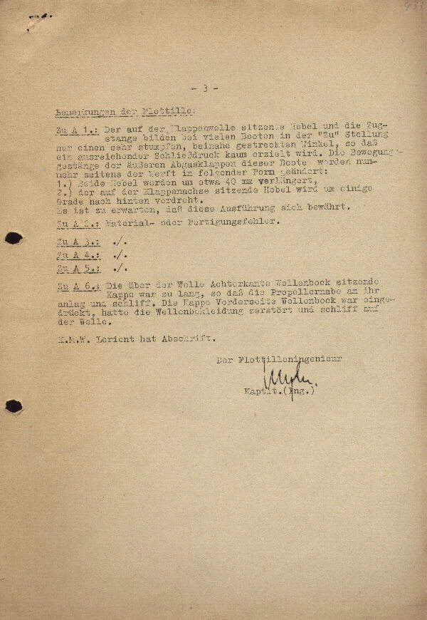
-3- Additionally A1.: Navy Yard Lorient Section.
The valve shaft handle is of the traction type which many boats have in the closed position, so that only a very blunt, acute angle pull may close the leak in the external gas flapper valve in these boats. Henceforth the following must be disposed of at the yard in following form:
1.) Both handles to be extended at about 40mm,
2.) In which the valve axis setting handle is set back about one degree.
It is advised that these measures be tried.
Additionally A2.: Material- or manufacturing defect.
Additionally A3.: ./.
Additionally A4.: ./.
Additionally A5.: ./.
Additionally A6.: where over the valve shaft eight edge shaft ram the cap was too long, so that your screw hub lays against it and grinds. The cap at the front side of the shaft ram was depressed, and the shaft ram assembly was destroyed and ground the shaft.
The Flotilla Engineer
[illegible signature]
Captain Lieutenant (Engineer)
Secret! 7) Obstructions in the diesel and E-motor compressor. 16) Damage to diving cell 8 and the water condenser port. 7) Obstructions in the diesel and E-motor compressor.
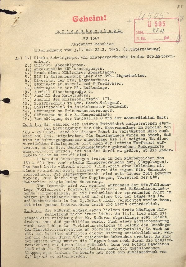
War Diary
"U-106"
Engineering Section
Operations from 3 January to 22 February 1942 (5th Operation)
A.)
1) Strong vibration and rattling noise in the starboard motor assembly.
2) Leaking exhaust valve.
3) Bulge in cool water pump.
4) Break in a cooling tube of exhaust gas flapper valve.
5) Rupture in the central section over the starboard exhaust turbine.
6) Oil loss in the starboard gas turbine.
8) Obstructions in the high pressure air systems.
9) Loss of cylinder group 6.
10) Loss of the main rudders.
11) Loss of the auxiliary switch board 111.
12) Ship shutting in starboard telegraph.
13) Ship shutting in power motor of lathe.
14) Obstruction in fresh water generator.
15) Obstruction in the E-compass assembly.
Additionally A1.: During conclusion of the last war patrol a strong vibration in the starboard motor assembly in the zone of 160-220 rpm. was reported. By the end of the patrol the degree of vibration had increased to over 400 rpm. The vibration was so strong, that the vibration meter registered measurement of about 1,2. That this strong vibration first occurred after last Yard time, where in the starboard vibration damper broke the exchanged spring packet, at the yard the test will be done to see if the spring packets are not tight.
Next to the vibration in the range of 160-220 rpm. is coming a strong clatter sound. (coupling). During its U.A.K.- time the boat had a collision with a concealed boat, and by this smashed the starboard screw. The clattering sounds began from this time. An overhauling of the junction, shifting the starboard E-engine shows no improvement.
As from Command we have measured exactly the starboard shaft assembly, controls for the diesel and E-principal machinery damage. The tachometer from the stores office is in transit from above mentioned tachometer section and through this long return course in the operational area an examination cannot be done, it is obligatory that an thorough examination at the yard be performed.
Additionally A2.: The external exhaust gas flapper valves are not always airtight despite continuous
cleaning. On 14th, Jan. the gears for the port external exhaust gas flapper valve turned very lightly without grinding. After an improvement in the weather the failure in the connecting bolts to the joints
of the gear rods in the superstructure remained firm. From the starboard side it appeared evident that a sudden breakdown occurred, with the screw bolts shifting through 1/2 inch. At the end of the operation the valves flaps barely maintained their seal fitting hold with the shutting mechanism., then in two machines the gear mechanisms of both flapper valves stopped rotating. This failure could only be halted by an external blowing of 0.4 kg/cm sq.
-2- The internal exhaust gas flapper stopped venting, it seems the gear shaft, especially at high temperatures, despite continuous lubrication, rotates very poorly (crooked shaft). With draining of external exhaust gas valves and closed drains, the packing of the pressure tight housings are have been sealed for a dive depth of A- 40m.
Additionally A3.: The crank position in the cupolas of the cool water pumps must be greater than 4 in case 6 weeks of operation is undertaken. The auxiliary crank position doesn't fit, the position is too great.
Additionally A4.: On 28.1 the cool water pump of the starboard exhaust gas turbine broke. The break occurred in the middle of the rubber threaded sleeve and 2 clamps leaked.
Additionally A5.: On 27.1 A rupture in the middle section over the starboard exhaust gas turbine occurred. Apparent material defect. The rupture was electrically welded, after two days there is still a small circular rupture.
Additionally A6.: Near higher operational combinations the oil ran through the labyrinth in the clean air shaft and continued to the motor, where it created major problems.
Cause: Leaking labyrinth.
Operations at the yard is mandatory.
Additionally A7.: On 20.1 the Diesel compressor failed.
a) Pressure in stage 3 climbed.
Cause: Piston ring stage 2 broken, part fell into stage 4.
Recovery of the broken part and replacement of the damaged piston rings.
b) Pressure vents leaking strongly.
Cause: Ball valve of the drain damaged. The ball will be replaced. Additional minor obstructions can be removed.
On 12.2 the E-air compressor failed through an increase in the pressure of stage 2 and 3. The pressure valve of stage 3 was broken and replaced.
Additionally A8.: Leaking in the blow manifold "main exhaust pressure valve compensating tank", water separator, pressure reducer through machining the valve setting, turning the cone with respect to the installation of the replacement tank of the pressure reducer removed. The main exhaust pressure valve compensating tanks were very frequently leaking, this was remedied with a shift in the stability setting and inserting a bronze cone. Through the work on these valves, the valves "blowing regulator and negative tank" and high pressure manifold were closed. During the overhaul time the negative (buoyancy) tank could not be compressed.
This would evade, when the joining of the main exhaust pressure valve compensating tank through a second valve is closed off.
Additionally A9.: On 1.2 [February] Occurred a strong air pressure loss from the high pressure air manifold. Through closings in the tank valves in the high pressure air manifold a pressure loss in tank group 6 was ascertained.
Therefore the port valve of tank group 6 is close. Because of the weather situation the obstruction in it can not be removed. Through a late examination a break in the supply tube to the tank was discovered. Cause: The support clamp had loosened,
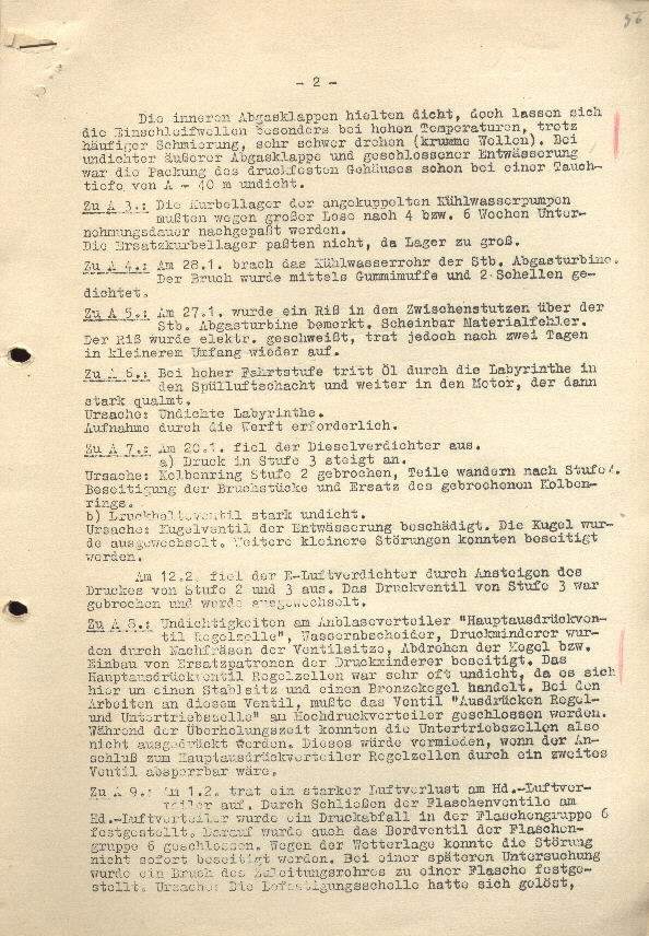
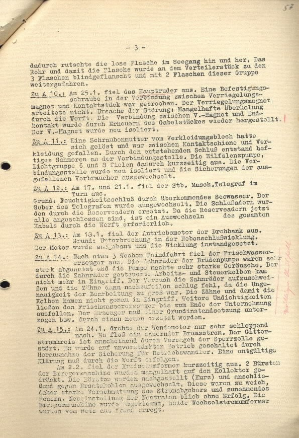
and by this slid the loose tank back and forth from sea force. With the tube bottle to the manifold piece of the 3rd tank blank flanged, and on 2 tanks we continued to drive on.
Additionally A10.: On 25.1 [January] Failure of the main rudder. A mounting screw in the cross connection between the locking magnet and the contact piece was broken. The locking magnet is non-functional. Cause of the obstruction: Defective overhaul at the yard. The cross connection between the L.-magnet end contact can through re fabrication of the yoke section, continue to be recovered.
The L.-magnet is newly insulated.
Additionally A11.: A shaft housing from the cowling sheet metal came loose and fell between the contact rail and cowling. A violent blow struck the upstanding end of the cross connection point. The secondary drainage pump, and light group 6 and 8 failed within short time. The cross connection point had a new insulation replacement and the failed auxiliary is replaced.
Additionally A12.: On 17. And 21. 1 [January] The starboard machine telegraph in the tower failed.
Cause: Moisture damage through leaking sea water. The transmitter of the telegraph was replaced. The close down was replaced with a reserve. The reserve is now completely connected, and its cable must be replaced at the yard.
Additionally A 13.: On 18.1 [January] the drive motor to the lathe failed.
Cause: Breakdown in the shunt motor wire winding. The motor and winding must be replaced urgently.
Additionally A14.: Up to about the 3rd week of the war patrol the fresh water generator failed. The gears to the vapor condenser pump were severely stripped and the pump produced a very loud noise. No further interference occurred in the gears helm works-and the rudder piston. In the test the gears were silent and the cog had the defects stricken off., The in exactness of the work (manufacturing) was great. The cog and with it the piston can not function exactly with this interference. Continual leaking is shutting down the fresh water generator which towards the end of operations, failed. The generator must be thoroughly pulled out and interchanged with a new replacement.
Additionally A15.: On 24.1 The rotating motor turned only very slowly. It maintains a continuous breaking current. The grating current orifice is apparently obstructed through a breakdown in the water tank. It was operationally weakened through removal of the securing for operational conversion. An effective purifying cleansing at the yard must occur.
On 2.2 failed the gyro stabilizer transformer in short time. 2 brushes to the excitation [electrical] machine are defective due to a depressed electrical connection. The brushes were [post positive] (short) and connected up to the exchanged replacement carbon. This was soaked and severely contaminated by the current transmitter and the increasing fire. New position of the neutral remains without consequence. The "excitation" machine jammed, both alternating current transformers became excited by outside excitation from the power circuit grid.
-4- The Chief Engineer
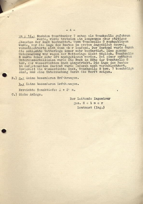
Additionally A16.: When the fuel reserve tank [ballast tank]7 already used as a reserve tank became endangered, in spite of going slow and steady, a sink in the bow was observed. When fuel cell 8 was blown, the position of the boat during the first moment was normal, but then was aggravated by running the engine. The condition was always aggravated more by the severe weather. An exact examination is not possible because of the weather. Reserve tank 8 must therefore be blown very frequently. By a later underwater collision the bow with respect to the level of reserve tank 8, the water pressure was lowered in the bow. The situation of the boats reserves standings is therefore worse. To what extent the water pressure in the bow reserve tank 8 with respect to no. 7 were damaged, a further inspection at the yard is indicated.
B.)
a.: No special experiences.
b.: No special experiences.
Available diving depth: A + 20m.
C.)
Self Arrangement.
Signed, Helmer
Lieutenant (Eng.)
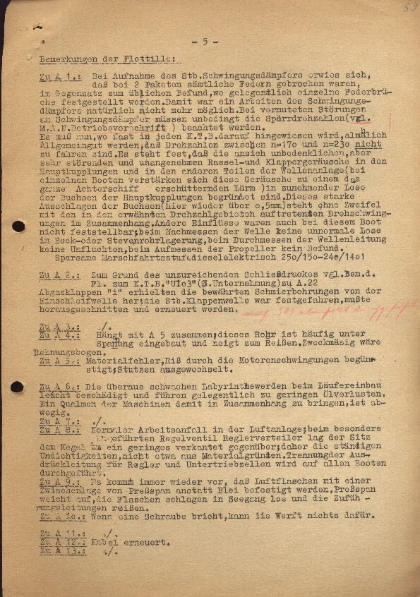
-5- Remarks by the Flotilla:
Additionally A1.: By activating the starboard vibration dampers it was established that 2 packets of the spring assembly were broken, contrary to standard results, where single spring breaks are normal. Because of this functioning in the vibration dampers naturally was no longer possible. Suspected obstruction of vibration dampers must be noted strictly according to the locking gear (M.A.N. Reliability regulations.)
It is now, as in each K.T.B. according to current knowledge, generally correct to set the rpm running between n=170 and n=230. Not ready to go. It stands firm, that the view is this is harmless, but very troubling and unpleasant rattling and clattering sounds in the main coupling and in other sections of the shaft beading ( in particular boats this strong shuddering sound can be heard in a quarter of the ship.) are caused by increasing looseness in the metal sheeting of the main coupling. This strong vibration in the sheeting ( here over 0.5mm) remains without a doubt connected to the available revolution speed and the associated acoustic effects. Another influence which surfaced from this boat: to measure the shaft for any abnormal loosening in the bilge [belly]-or stem tube beading, by measuring through the shaft pipeline for elimination of drifting, which has not been found in the propeller.
Economize on diesel electric fuel 250/150-240/140!
Additionally A2.: The cause of the insufficiencies in the closed pressure compressor system, refer to the notes from K.T.B.( war diary) "U103" ([?] Operation) to A.22
Exhaust gas flapper valves "I" obtained an effective grinding shaft lubricating bore.; The starboard valve shaft was grounded, it must be replaced in sections.
Additionally A3.: ./.
Additionally A4.: Connected together with A5; this tube is frequently built in under pressure and inclined while traveling. Functional when it is elongated in a curve.
Additionally A5.: Material defect, damage by the motor vibration increase; defected part replaced.
Additionally A6.: The overall problems with the continuing repairs of the labyrinth are light damage followed by the occasional small oil leak. An unusually thick smoke from the machine comes with it, connected the damage.
Additionally A7.: ./.
Additionally A8.: Normal work load in the Air System; through special operation across the regulator valve regulator manifold position of the plug lays across the seat of the hub at a slight cant. The continuing leak is not caused by material base. Separator pressure pipes for regulator and negative tanks were taken from all boats.
Additionally A9.: It always occurs, the air bottles with intermediate storage capacity instead of lead. Pressure leaked out, as the bottles were damaged by sea force and the supply pipes ruptured.
Additionally A10.: If a propeller brakes, it is not possible to return to the yard.
Additionally A11.: ./.
Additionally A12.: Cable replaced.
Additionally A13.: ./.
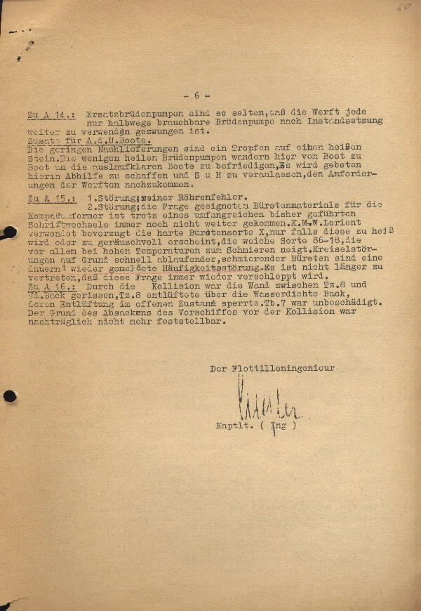
-6- Additionally A14.: Auxiliary vapor concentrate pumps [AVCP] are so scarce, that the yard will deploy half functional auxiliary vapor concentrate pumps for replacement.
Addition for A. D . U Boat.
The small additional delivery are a drop out of a hot stone. The few undamaged AVCP's travel from boat to boat and whenever one is free for exchange, it will be offered as help is needed and requested, the request to the yard will also come.
Additionally A15.: 1. Damage; clean tube defect.
2. Damage; the problem of suitable brush material for the compass motor generator is so far, unresolved because of an unsuccessful operational written request, Navy Yard Lorient: preferable application for the hard brush is a 10, only these have failed due to heat exposure or sound damage, during the retreat [sortie] 86-18 Due to high temperature increase all brushes were lubricated. Gyro damage from the bottom, [flooding] in precisely drained off, quickly. Lubrication of the brushes will be a further step toward resolving this problem. This is no longer a question of concern.
Additionally A16.: Due to the collision the barrier between diving cell 8 and the bow barrier, diving cell 8 is being ventilated out of the water tight bow, [aperture] the Tb7 is in a state of open venting and was undamaged. The base sink rate of the fore ship from the collision has not been ascertained.
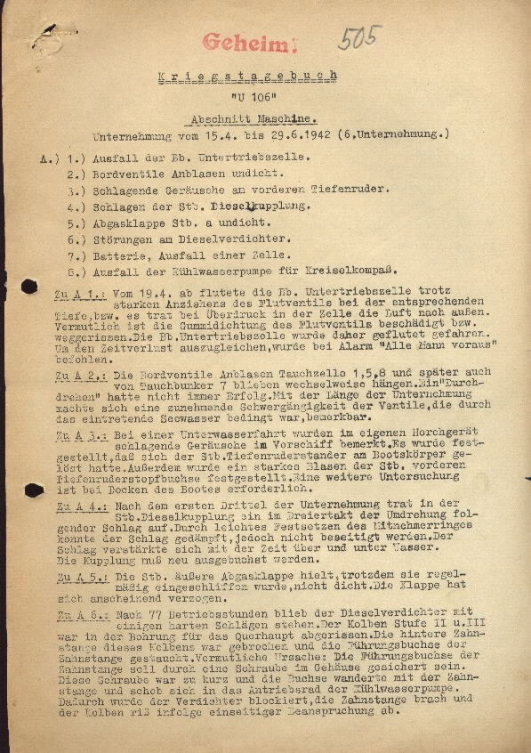
Secret! 8. Failure of the cool water pumps for the gyro-compass.
War Diary
"U 106"
Engineering Section
Operations from 15 April to 29 June 1942 (6th Operation.)
A.)
1.Failure of port negative buoyancy tank.
2. Hull valve ballast leak.
3. Vibrating noise on the forward hydroplane.
4. Striking on the starboard diesel clutch.
5. Exhaust gas flapper starboard leak.
6. Obstruction in the diesel compressor.
7. Batteries, failure of a cell.
Additionally A1.: From the 19.4 flooding in the port negative buoyancy tank due to strong draw on the flood valves at the appropriate depth followed by high pressure in the cell's air exhaust. Probable that the rubber seal for the flood valves are damaged in transit. The port negative buoyancy tank therefore became dangerously flooded. In about the same time, the alarm sounded "All Men Forward".
Additionally A2.: The hull valve ballast dive cell 1,5,8 remain caught up, and later alternately the diving bunker 7. An "attempted removal" was not always successful. With the length of the operation causing it to make things very difficult for the valves, which was noticed through the intrusion of see water.
Additionally A3.: During a journey underwater a special listening device vibration sound in the for ship was noticed. It was established that the starboard hydroplane guard on the boat body [hull] had been lost. Also a severe flaw in the starboard forward hydroplane sleeve was ascertained. A further examination of the boat at the dock is required.
Additionally A4.: After the first third of the operation damage to the starboard diesel clutch coupling was pulled out in triple time. By the minimal remedies undertaken it was possible to dampen the vibration sound. The vibration became stronger as time passed above and below water. The clutch coupling must be booked for replacement.
Additionally A5.: The starboard external exhaust gas flapper held, in spite of periodic grinding, no leak. The flapper valve had apparently been misshapen.
Additionally A6.: Up to 77 operational hours the diesel compressor continues to operate with a strong vibration. The piston stages 11 and 111 are transversely traveling through the bore [cylinder] in an oblique angle.
The reverse side of the gear rod of this piston was damaged and had pushed into the driving wheel of the cool water pump. By this, the compressor became blocked, the gear rod broke and the piston fractured due to one sided stress loads.
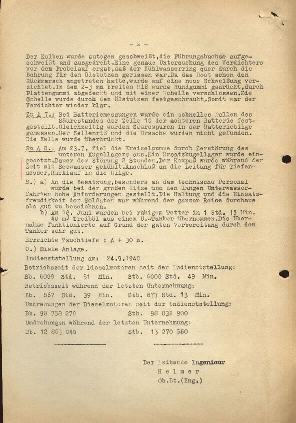
-2- The piston was [autogen] welded, the pilot bushing welded shut and switched off. A thorough investigation of the compressor and a test run was made, and the cool water ring broke through the bore orifice for oil flow. By such reliable welding, the boat has already made course for the return journey. A rubber sheet was pressed through the 2-3 mm wide rupture and closed secure with a clip. The clip was screwed through the oil flow. By this the compressor was kept clear.
Additionally A7.: Through battery measurements a rapid decrease of the oxygen level in cell 10 of the 8thbattery was determined. Equal measurements of the oxygen flow in the battery bilge were taken. The cell rupture and the cause were not found. The cell was bridged.
Additionally A8.: On 23.7 the circulating pump failed through destruction of the lower spherical tanks. A replacement spherical tank was substituted. The obstruction lasted 2 hours. During this time the compass was cooled with see water. Supply in the piping for the depth meter, return line is in the bilge.
B.)
a) About the crew, especially the technical personnel whom during the high intensity and the less than tolerable underwater travel set high standards. The bearing and the keenness of the soldiers was throughout the entire journey good to witness.
b) On 18. June with quiet weather in 1 hour 15 min. 40 cubic meters of fuel oil from a U boat tanker were taken on. The operation functioned in principal with the tankers very good preparations.
Attainable depth: A + 30 m.C.)
See Layout.
Commissioning on: 24.9.1940
Operating time of the diesel motor since the [commissioning, mobilization?]:
Port 6009 Std.
51 min.
Starboard 6000 Std. 49 min.
Operating time during the last operation:
Port 867 Std.
39 min.
Starboard 877 Std. 13 min.
Revolutions of the diesel motor since the [commissioning, mobilization?]:
Port 98 758 270
Starboard 13 270 560
The lead engineer
Helmer
1st. lieut. (engineer)
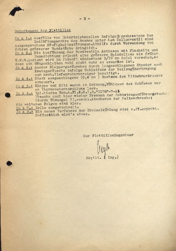
-3- Remarks by the Flotilla: The Flotilla Engineer
Additionally A1.: Loss of the negative buoyancy tank as a result of marked frequent obstructions through the ventilation tube.
Additionally A2.: The implementation of the hull valve blowing with flax lubrication of the rubber gasket permits a higher spindle speed than earlier.
Navy Yard Lorient will see in the future at least 5/10 mm of play, so that a fastener will no longer be necessary.
Additionally A3.: External clapping sound released through the continual vibration caused by scraping due to the abrasion in the line transmission for the mechanical hydroplane indicator. Repair.
Additionally A4.: Strong vibration in the (0.6mm) sheeting for the transfer lever cam cross renewed.
Additionally A5.: Valve lid and base were in order, cool space in housing was leaking in the thermometer assembly.
Additionally A6.: The following are the remarks from the flotilla for the war diary of the "U-108" -7-A.
Here the cause again is the gear rod operator sheeting (due to defective oil?) connection sheared off for support screw; follow up is clear.
Additionally A7.: Cell replaced.
Additionally A8.: A new procedure for the rotary cooling is to be put to the test. Hopefully something will come of it.
[illegible signature]
Capt. Lieut. Eng.)
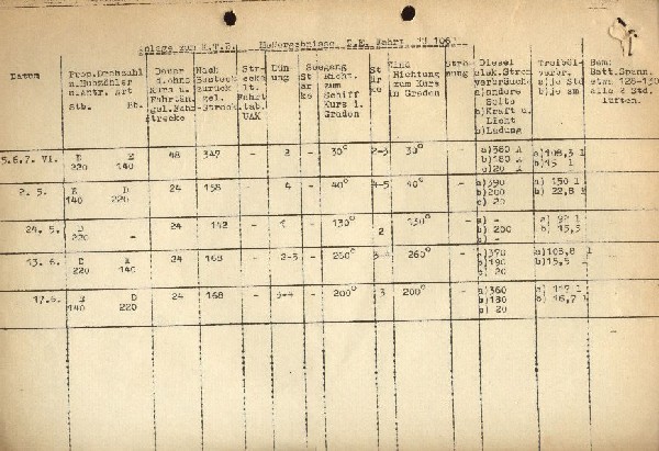
Datum |
5.6.7.VI |
5.6.7.VI |
5.6.7.VI |
5.6.7.VI |
5.6.7.VI |
Prop. rpm as indicated under driving speed Starb. Pt. |
D E |
D E |
D E |
D E |
D E |
Duration without course and position |
48 |
48 |
48 |
48 |
48 |
Return position |
347 |
347 |
347 |
347 |
347 |
Distance travelled |
- |
- |
- |
- |
- |
Swell |
2 |
2 |
2 |
2 |
2 |
Power |
- |
- |
- |
- |
- |
| Wind direction in degrees | 30 |
30 |
30 |
30 |
30 |
Current |
- |
- |
- |
- |
- |
D.E. Current In Amps. a)other side b)power and light c)load |
a)380 |
a)380 |
a)380 |
a)380 |
a)380 |
Fuel oil Burnt a)std b)sm |
a)108.31 |
a)108.31 |
a)108.31 |
a)108.31 |
a)108.31 |
Battery voltage 128-1302 hoursto air |
|
|
|
|
|
“U-106” Operations from 25-29 July 1942 (7th Operation broken off early)
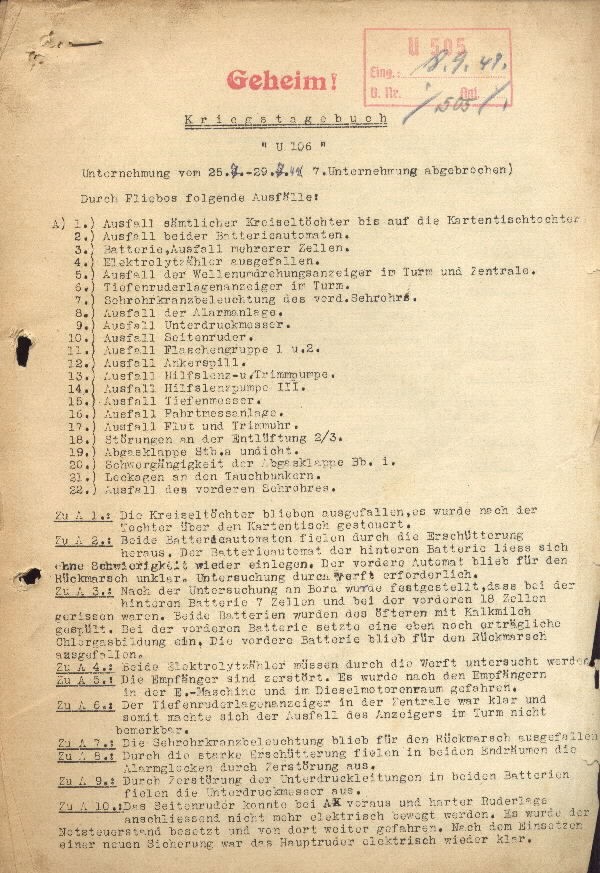
Through journey closing losses:
A)
1.) Loss of complete centrifugal subsidiary up to the chart table subsidiary.
2.) Loss of both auto batteries.
3.) Batteries. Loss of additional cells.
4.) Loss of electrolyte meter.
5.) Loss of shaft rotation (rpm) indicator.
6.) Hydroplane indicator in the tower.
7.) Azimuth circle illuminator of the forward periscope.
8.) Loss of the alarm system.
9.) Loss of diving meter.
10.) Loss of side rudder.
11.) Loss of tank group 1 and 2.
12.) Loss of anchor.
13.) Loss of auxiliary bilge- and trim pump.
14.) Loss of auxiliary bilge pump 3.
15.) Loss of depth gage.
16.) Loss of navigation system.
17.) Loss of tide and trim clock timer.
18.) Obstruction in the vent 2/3.
19.) Exhaust gas valve starboard and leak.
20.) Difficult passage in the exhaust gas valve port.
21.) Leaking in the dive bunker.
22.) Loss of the forward periscope.
Additionally A1.: The centrifugal [subsidiary repeater] remains out of operation. It shifted up to the [subsidiary] over the chart table.
Additionally A2.: Both auto batteries lost through shock vibration.
Additionally A3.: After the investigation on board, confirmed, that two of the aft battery cells and two of the forward 18 cells were damaged. Two batteries were repeatedly rinsed with limewater. The forward battery remains in a tolerable chlorine gas.
Additionally A4.: Both electrolyte meters must undergo investigation at the yard.
Additionally A5.: The receivers are destroyed. It occurred at the end of journey.
Additionally A6.: The hydroplane indicator in the control room was clear, and therefore made the loss of the indicator in the tower un noticeable.
Additionally A7.: The periscope azimuth indicator remains lost for the return journey.
Additionally A8.: Through strong vibration failure of both aft ship alarm bells.
Additionally A9.: Through destruction of the vacuum lines in both batteries. Loss of the vacuum meter.
Additionally A10.: The side rudder can not deflect forward and back any longer by electronic means. After replacement with new security the main rudder electronically clear.
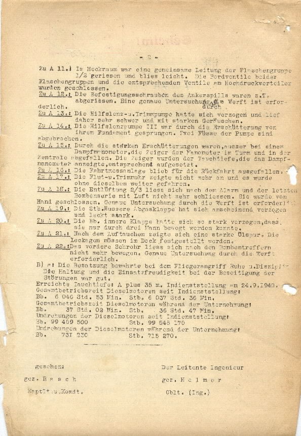
Additionally A11.: In the stern space a combined line of the container group ½ damaged and light blowing. The hull valve of both container groups and the corresponding valves on the high pressure manifold were closed.
Additionally A12.: The support screws of the anchor capstan were damaged. A thorough investigation at the yard is mandatory.
Additionally A13.: The auxiliary bilge and trim pump had dislodged themselves and are in a severe state and with severe noise.
Additionally A14.: The auxiliary bilge pump 111 was cracked through the vibration from the foundation. Two footings to the pump are broken.
Additionally A15.: Through strong vibration, externally one of the steam gage, the indicator of the meter in the tower and the control are lost. The indicator for the dive, the steam gage, ordered repaired.
Additionally A16.: The position indicator for the return journey remains lost.
Additionally A17.: The flood- and trim counter indicator can no longer continue travel without diesel drive.
Additionally A18.: The venting 2/3 dropped off after the alarm and the last bombing series with the air no longer closed off. They were closed by hand. A thorough investigation at the yard is required.
Additionally A19.: The starboard external exhaust gas flapper valve had apparently been pulled and deformed and is leaking severely.
Additionally A20.: The port internal flapper had been so severely deformed, that it can be operated only through three men.
Additionally A21.: After the dive a severe oil leak occurred. The leak must be repaired at the dock.
Additionally A22.: The forward periscope remains inoperable after the bombing damage. Thorough investigation at the yard is required.
B) a: The crew maintained throughout the air attack quiet and disciplined. The posture and the keenness while repairing the obstructions were good.
Attainable depth: A plus 35m.
Commissioning on 24.9.1940.
Operational time for diesel motors since commissioning:
Port 6 046 hours 53 min.
Starboard 6 037 hours 36 min.
Operational time for diesel motors during the operation:
Port 37 hours 02 min.
Starboard 36 hours 47 min.
RPM’s for diesel motors since commissioning:
Port 99 489 500
Starboard 99 548 170
RPM’s for diesel motors during the operation:
Port 731 230
Starboard 715 270.
Witnessed:
Signed [Captain Lieutenant Hermann Rasch] Rasch
Capt. Lieut. Comnt. The Chief Engineer
Signed Helmer
1st. Lieut. (Eng.)
The Flotilla Engineer
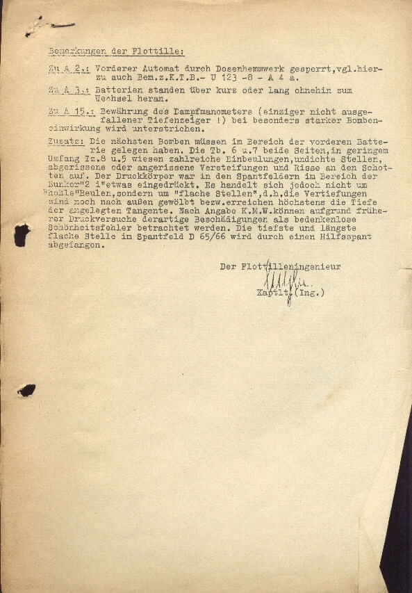
Remarks by the Flotilla:
Additionally A2.: Forwarding automatically through closed network halted. The following from here out comes from the war diary – U-123 –8 –A 4 a.
Additionally A3.: Battery standing over short or long without being replaced.
Additionally A15.: Success with the steam gages (only not with lost depth indicator!) by particularly severe bombing effects are underscored.
Addition: The last bombing must have impacted in the area of the forward battery. The batteries 6 and 7 in both sides, in the lower range main ballast tanks 8 and 5 retained a large number of dents, standing leaks, damage or ruptures in the hardened and cracked bulkhead. The pressure hull was in the spacing area of the bunker 2 [something pressurized ?] The operation to each “hole” blister, especially in the “level places”, that is, the deepening is not always in a curve with respect to ruptures high in depth to the tangential layout. After the statement by the Navy Yard on account of earlier pressure testing to determine extent of the damage, there was without doubt a failure of duty. The low and long flat place in auxiliary frame D 65/66 was submerged through an auxiliary frame.
[signature]
Capt. Lieut. ( Eng.)
Note: The library has additional un-translated and fragile damage reports captured on U-505 from the following German submarines:U-106 (covering the period 21 Oct.-4 Apr. 1943), U-108 (Aug. 1941-24 Feb. 1943), U-109 (25 Mar. 1942-1 Apr. 1943), U-123 (23 Dec. 1941-8 Jun. 1943), U-124 (21 Feb. 1942-13 Feb. 1943), U-125 (Feb. 1942-19 Feb. 1943), U-126 (5 Jul. 1941-25 Jul. 1942), U-128 (25 Apr. 1942-15 Jan. 1943), U-129 (28 Sep. 1942-6 Jan. 1943), U-130 (1 Dec. 1941-6 Jan. 1942), U-137 (14 Sep. 1940-27 Nov. 1940), U-140 (26 Nov. 1940-), U-153 (10 May 1942-30 May 1942), U-154 (9 Feb. 1942-6 Jul. 1943), U-156 (19 Jan. 1942-7 Jul. 1942), U-157(30 Apr. 1942-5 Oct. 1942), U-162 (7 Feb. 1942-8 Jun. 1942), U-168 (3 Mar. 1943-18 May 1943), U-183 (30 Jan. 1943-13 May 1943),U-190 (5 Jan. 1943-Aug. 1943), U-502 (29 Sep. 1941-9 Nov. 1941), U-504 (19 Jan. 1943-25 Jan. 1943), U-507 (4 Apr. 1942-4 Jun. 1942), U-518 (Jan.-Apr. 1943), U-521 (7 Jan. 1943-30 Mar. 1943), U-A (18 Mar. 1941).
[END]


