
The Navy Department Library
Destroyer Report
Gunfire, Bomb and Kamikaze Damage Including Losses in Action 17 October, 1941 to 15 August, 1945
The Chief of Naval Operations directs that this report be shown only to those persons to whom the report would be of value in the performance of their duties.
Steps shall be taken accordingly to insure that the report will be seen by those persons responsible for design, construction and repair of naval vessels, as well as for their operation, but by no others.
Preliminary Design Section
Bureau of Ships
Navy Department
25 January, 1945
WAR DAMAGE REPORT No. 51
Printed By U. S. Hydrographic Office
CONTENTS
| Page | Section |
| 1 | I FOREWORD |
| II SUMMARY AND DISCUSSION | |
| A. General | |
| 9 | B. Effect of Kamikaze Tactics |
| 10 | C. Enemy Weapons |
| 11 | D. Structural Damage and Hull Strength |
| 13 | E. Buoyancy, Stability and Control of Flooding |
| 17 | F. Fire Protection |
| 19 | G. Ammunition Behavior |
| 23 | H. Machinery Damage and Casualty Control |
| 25 | I. Conclusions |
| Ship Name | DD No. | Standard1 Displacement | Damaged By | Date | ||
| 28 | III | RALPH TALBOT | 390 | 1500 | Gunfire | 8/9/42 |
| 37 | IV | JOHNSTON | 557 | 2050 | Gunfire | 10/25/44 |
| 42 | V | ALBERT W. GRANT | 649 | 2050 | Gunfire | 10/25/44 |
| 58 | VI | AARON WARD | 483 | 1630 | Bomb | 4/7/43 |
| 62 | VII | MAYRANT | 402 | 1500 | Bomb | 7/26/43 |
| 73 | VIII | SHUBRICK | 639 | 1630 | Bomb | 8/4/43 |
| 80 | LX | BROWNSON | 518 | 2050 | Bomb | 12/26/43 |
| 84 | X | KILLEN | 593 | 2050 | Bomb | 11/1/44 |
| 95 | XI | ABNER READ | 526 | 2050 | Kamikaze | 11/ 1/44 |
| 102 | XII | HUGH W. HADLEY | 774 | 2200 | Kamikaze | 5/11/45 |
| 112 | XIII | STORMES | 780 | 2200 | Kamikaze | 5/25/45 |
TABLES
TABLE I - Analysis of 251 Reported Instances of Destroyer Damage by Enemy Action
TABLE II - Governing Elements in Loss of Destroyers Sunk by Gunfire, Bomb or Kamikaze Attack
PHOTOGRAPHS
Appropriate views of damage and repairs are included in Sections II, III, V, VII, VIII, X, XI, XII and XIII.
PLATES
At the end of each section concerning an individual ship's damage a plate is included to show the arrangement in way of the damage. These plates were prepared by this Bureau and usually were based on similar drawings forwarded by the ship or the repair activities.
1 Standard displacement is a term established by the Washington Naval Treaty of 1922 and is defined as normal wartime displacement less fuel and water. With the lapse of the treaty in 1936 this tonnage became merely nominal. The 2050-ton Class is generally known as the 2100-ton Class and actually displaces around 2700 tons in what might be considered a typical combat condition with a two-thirds load of ammunition, fuel and provisions.
SECTION I
FOREWORD
1-1 This report and War Damage Report No. 50 analyze cause, effect and countermeasure of damage received in action in the recent war by U.S. destroyers. Damage from torpedoes and mines is covered in Report No. 50, while this report embraces damage caused by gunfire, bomb and Kamikaze attack. The purpose of the two reports is to present, after sifting the great volume of destroyer war experience, information of lasting value to damage control and engineering personnel aboard destroyers and subsequent vessels of which they are the prototype, to salvage and repair activities, and to those responsible for the design and outfitting of similar vessels. No attempt is made to anticipate the effect of the recent CROSSROADS OPERATION on the future of destroyers. Undoubtedly, much of the information herein on ammunition behavior will be outmoded as new weapons are developed; however, the damage control problem remains essentially the same though the relative importance of various factors will change.
1-2 Eleven cases of destroyer damage have been taken up in detail in this report and are grouped as follows: three cases of damage by gunfire, five exclusively by bombs and three by Kamikaze crashes. The cases chosen are typical of damage incurred by destroyers from each of these three types of attack. The sequence of cases, within each group, is chronological. It will be noted, therefore, that the latter cases of each group involve ships of later and improved design and probably more adequately trained crews, the two factors together accounting for the greater resistance of later destroyers. The text of each case includes a narrative describing the action, the damage and the damage control measures including a resume of salvage or interim repair procedure, a discussion of the ordnance material which inflicted the damage and also such conclusions as may be drawn regarding material design and damage control technique. For the sake of brevity, the discussions of ordnance, communications and medical problems in the damaged ships have been limited to those phases which directly concerned the ship's survival.
1-3 A general summary and discussion precede the detailed case analyses in this report so that those whose duties preclude time for perusal of the entire report may more readily obtain the salient data.
1-4 By odd coincidence what were probably the two most spectacular cases of survival after very extensive damage in destroyer hulls occurred not to DD's but to DM's converted from vessels of the short-hull DD692 Class. Illustrations of these two cases immediately follow this Section. Their damage experience has not been taken up in further detail because they were no longer, in the strict sense, destroyers.
--1--
SHIP AARON WARD (DM34)
2200 Tons Standard
Damaged in Action off Okinawa 3 May 1945
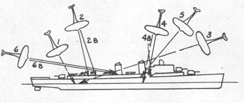
1 Near miss crash. Engine and propeller hit Mt. 3.
2 ZEKE hit Mt. 44. 2B Bomb blew out side after engineroom.
3 Near miss crash damaged rigging and No. 1 stack.
4 VAL hit main deck, frame 81.
4B Near miss bomb blew in side forward fireroom.
5 VAL crashed deckhouse, frame 90.
6 Plane hit after stack.
6B Bomb detonated in after uptakes.
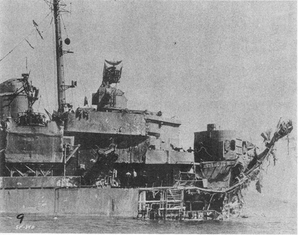
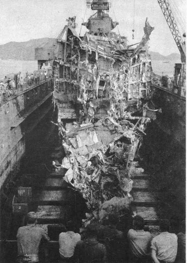
Photos 2-1 and 2-2: The two photographs on the page opposite are classic illustrations of the survival power of the modern U.S. destroyer. The AARON WARD shown was one of the minelayers converted from 692 Class destroyers and should not be confused with DD483 which was sunk in 1943. She was hit as shown in the above diagram by six Kamikazes and three large bombs, estimated to have been 250 Kg GP. All spaces between bulkheads 72 and 170 flooded to the waterline except for the forward engineroom and certain starboard water tanks. Free surface extended through five major compartments, 1650 tons of water were shipped and GM was reduced to approximately 1 foot positive. Severe gasoline and ammunition fires were brought under control after about two hours with the assistance of LCS83 alongside. Firemain pressure and power forward remained available throughout due to use of the forward emergency Diesel generator. AARON WARD arrived at Kerama Retto with no freeboard aft, 18 feet draft forward and a 5-degree starboard list. After emergency repairs she proceeded under her own power to Navy Yard, Pearl Harbor, using the starboard shaft.
--2--
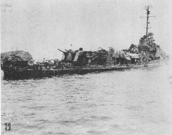
![Photo 2-2: AARON WARD (DM34) at Kerama Retto, May 1945. [viewing from the opposite side] Photo 2-2: AARON WARD (DM34) at Kerama Retto, May 1945. [viewing from the opposite side]](/content/history/nhhc/research/library/online-reading-room/title-list-alphabetically/w/war-damage-reports/destroyer-report-gunfire-bomb-kamikaze-damage/_jcr_content/body/image_2.img.jpg/1425384411820.jpg)
--3--
SHIP LINDSEY (DM32)
2200 Tons Standard
Damaged in Action off Okinawa 12 April 1945
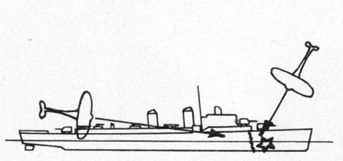
First Hit: VAL approached from astern and crashed along starboard side as far forward as frame 69. Small bomb detonated, fragments penetrating depth charges.
Second Hit: VAL with bomb in steep dive hit port side frame 30 at first platform level. Magazine explosion blew off bow including Mt. 1.
Photos 2-3 and 2-4: The two photographs on the opposite page illustrate the effect of a powder explosion in No. 1 magazine on a 2200-ton Class destroyer. LINDSEY, a minelayer conversion from DD692 Class vessel, was hit as indicated in the diagram. The second hit occurred about one minute after the first. Simultaneously with the second hit a heavy dull explosion took place accompanied by heavy brown smoke. Observers also identified a sharp report believed to have been due to the detonation of the second plane's bomb. Evidence indicates that the magazine explosion consisted of a mass deflagration of 5 -inch powder cartridges in A-404-M on the third platform level, frames 18 to 26. This magazine was separated from the group two magazine by the refrigerated spaces. Keel sheared at frame 30. Main deck hinged upward at about frame 60. Flooding extended to bulkhead 72. Trim by the bow increased only about 18 inches. Main propulsion plant and gyro remained intact. Local control of the after battery was regained a few minutes after the hit. LINDSEY made port stern first assisted by tow. After emergency repairs at Kerama Retto, during which bulkhead 60 was made watertight, LINDSEY was towed stern first to Guam. Return to Norfolk was made on own power with false bow installed at Guam.
--4--
--5--
SECTION II
SUMMARY AND DISCUSSION
A. General
2-1 There have been reported to the Bureau of Ships 251 instances of damage to U.S. destroyers resulting from enemy action between 17 October 1941 and the cessation of hostilities on 15 August 1945. These cases may be classified by cause and result as follows:
TABLE I
Analysis of 251 Reported Instances1 of Destroyer Damage by Enemy Action
| Cause | Gunfire, Bomb or Kamikaze | Torpedo or Mine | Miscellaneous2 |
| Result | 30 sunk | 27 sunk | 3 sunk |
| 162 survived | 21 survived | 8 survived | |
| 84% survival | 44% survival | -- |
1 In many cases a single instance represents multiple hits or near misses.
2 Miscellaneous includes strafing, suicide boats, ramming and unknown.
Note: Approximately 30 cases of damage to destroyers converted to minecraft occurred. These have not been included in the table.
2-2 In any consideration of the survival powers of the modern destroyer, the personnel factor must be recognized. The ship as built has proved its ruggedness but many vessels survived unprecedented damage largely due to the high degree of training and the heroic determination of the ship's damage control organization. For the same reasons, several that were eventually lost were enabled to remain in action appreciably longer. A study of a loss is often even more instructive than one of a survival, provided enough data are available to make a thorough analysis. In four of the eleven cases taken up in detail in this report, the ship sank. The selection of a case for inclusion in this report does not imply that it represents either one of the best or one of the poorest performances but simply that the case is illuminating and the damage control problems instructive.
2-3 The fundamental treatise in the U.S. Navy on the subject of damage control is the pamphlet entitled, "Damage Control Instructions, F.T.P.170(B),"1 issued by the Chief of Naval Operations. F.T.P.170(B) defines damage control as comprising the maintenance of fire power, mobility, maneuverability and floatability, and states that it is to be accomplished by the preservation of stability and buoyancy, by control of list and trim, by the rapid repair of structure, vital systems and equipment, by counteracting the effects of fire, and by facilitating the care of personnel casualties. The size of a destroyer is such that, after major damage, firefighting and the preservation of stability and buoyancy are usually the problems of prime consideration in the ship's survival. There is little that the ship's company can do on the spot to repair major damage to either the structure or the engineering plant.
__________
1 A new publication, U.S.F. 81, is scheduled to supersede F.T.P. 170(B) in 1947.
--6--
2-4 In a damaged destroyer, reserve buoyancy, stability characteristics, and extent of flooding are closely inter-related and it is impracticable to consider one independently of the others. Our modern destroyers are largely four-compartment ships; i.e., four major compartments extending from one main transverse bulkhead to the next may be freely flooded from the sea before the main deck becomes awash. It is attempted in basic design to give these ships stability characteristics commensurate with this floodable length. It is therefore unlikely that a properly loaded destroyer would capsize prior to the virtual elimination of reserve buoyancy. Abnormal winds and wave forms in severe cyclonic storms have caused some destroyers to capsize without extensive flooding, but this is exceptional. The preservation of adequate buoyancy and stability is largely contingent upon the control of flooding.
2-5 Fires hazard the ship's survival not only because they may initiate explosions which demolish large sections of the ship but also because in ships of destroyer size and smaller, particularly, they seriously interfere with handling the other problems that ensue after damage is incurred. Fires normally must be brought under control before control of flooding can be undertaken. Firefighting techniques so far have been much more efficient than those employed to control flooding. For this reason more destroyer losses are attributable to progressive flooding than to fire.
2-6 Mine and torpedo hits have resulted in the loss of destroyers in a higher percentage of cases than have gunfire, bomb or Kamikaze hits, primarily because the underwater ordnance carried a larger explosive charge to a more vulnerable spot. In general, the impact and blast of a projectile or a bomb, or a Kamikaze with its bomb load caused damage centered above the waterline. In numerous cases, abnormal charges or repeated hits topside have caused structural damage as extensive as that resulting from a torpedo, but being in a less critical area with respect to flooding, the damage was not so frequently fatal. In the future, the efficiency of bombs or of guided missiles or pilotless aircraft may be increased to that of torpedoes through the use of more powerful explosive charges and improved fuzing; however, the most effective attack will remain that which introduces flooding.
2-7 As shown in TABLE I, the loss of 30 U.S. destroyers can be ascribed primarily to enemy action involving gunfire, bomb or Kamikaze attack. The further analysis in TABLE II below showing how the losses occurred is in some cases arbitrary because, from the frequently incomplete data afforded by survivors, the sequence in which reserve buoyancy or stability was lost, structure failed, or explosions occurred will never be determined.
--7--
TABLE II
Governing Elements in Loss of Destroyers Sunk By Gunfire, Bomb or Kamikaze Attack
A. Flooding - 14 Losses |
|||||
| a. Loss of buoyancy aggravated by radical list - | |||||
| 1. | PRESTON (DD379) | 1500T | Gunfire | Guadalcanal | 11/15/42 |
| 2. | MADDOX (DD622) | 1630T | Bombs | Sicily | 7/10/43 |
| 3. | HOEL (DD533) | 2050T | Gunfire | Samar | 10/25/44 |
| 4. | JOHNSTON (DD577) | 2050T | Gunfire | Samar | 10/25/44 |
| 5. | REID (DD369) | 1500T | Kamikaze | Leyte | 12/11/44 |
| 6. | DREXLER (DD741) | 2200T | Kamikaze | Okinawa | 5/28/45 |
| b. Loss of buoyancy aggravated by radical trim - | |||||
| 1. | SIMS (DD409) | 1570T | Bombs | Coral Sea | 5/7/42 |
| 2. | DUNCAN (DD485) | 1630T | Gunfire | Guadalcanal | 10/12/42 |
| 3. | CALLAGHAN (DD792) | 2050T | Kamikaze | Okinawa | 7/29/45 |
| 4. | LUCE (DD522) | 2050T | Kamikaze | Okinawa | 5/4/45 |
| 5. | MORRISON (DD560) | 2050T | Kamikaze | Okinawa | 5/4/45 |
| 6. | W.[illiam] D. PORTER (DD579) | 2050T | Kamikaze | Okinawa | 6/10/45 |
| c. Loss of buoyancy on relatively even keel - | |||||
| 1. | DeHAVEN (DD469) | 2050T | Bombs | Guadalcanal | 2/1/43 |
| 2. | AARON WARD (DD483) | 1630T | Bombs | Guadalcanal | 4/7/43 |
B. Structural Failure - 6 Losses |
|||||
| a. Jackknifed - | |||||
| 1. | BROWNSON (DD518) | 2050T | Bombs | Cape Gloucester | 12/26/43 |
| 2. | BUSH (DD529) | 2050T | Kamikaze | Okinawa | 4/6/45 |
| 3. | MANNERT L. ABELE (DD733) | 2200T | Kamikaze | Okinawa | 4/12/45 |
| 4. | PRINGLE (DD477) | 2050T | Kamikaze | Okinawa | 4/16/45 |
| 5. | LITTLE (DD803) | 2050T | Kamikaze | Okinawa | 5/3/45 |
| b. Sagged by the stern | |||||
| 1. | COLHOUN (DD801) | 2050T | Kamikaze | Okinawa | 4/6/45 |
C. Magazine Explosion - 5 Losses |
|||||
| a. On direct hit - | |||||
| 1. | LONGSHAW (DD559) | 2050T | Gunfire | Okinawa | 5/18/45 |
| b. Following fire - | |||||
| 1. | CUSHING (DD376) | 1500T | Gunfire | Guadalcanal | 11/13/42 |
| 2. | MONSSEN (DD436) | 1630T | Gunfire | Guadalcanal | 11/13/42 |
| 3. | ABNER READ (DD526) | 2050T | Kamikaze | Leyte | 11/1/44 |
| 4. | MAHAN (DD364) | 1500T | Kamikaze | Ormoc | 12/7/44 |
--8--
Note (a) CASSIN (DD372) and DOWNES (DD375), which were in dock when damaged, and three 1200-ton destroyers have been omitted from the above report. Also omitted are several cases in which a torpedo hit was involved in addition to gunfire or bomb hits.
(b) The word "capsized" has been deliberately avoided in the headings of the above table in order to describe more accurately the manner of sinking. In certain cases, heavily damaged warships, notably BB's, CV's, CVE's and CA's, both foreign and U.S., have rolled over so as to expose the keel and remained bottom up for a short period before sinking. This behavior can quite properly be described as capsizing. In the DD's listed in the table this has not occurred. Where complete loss of transverse stability has occurred in these ships it has come about virtually simultaneously with the exhaustion of reserve buoyancy. Excessive trim, sometimes indicative of the loss of longitudinal stability, has also made it difficult to draw the line between groups in the table. Some of the destroyers lost have listed about 90 degrees before they submerged, also some have canted their bows or sterns almost perpendicularly as they sank, but in each case the loss has been so rapid that it is not accurate to attribute the loss of the ship entirely to the loss of either transverse or longitudinal stability.
B. Effect of Kamikaze Tactics
2-8 A short digression on Kamikaze, or suicide plane tactics, is appropriate in view of the fact that nearly half of the destroyers damaged during the war by above-water weapons were victims of this form of attack. Destroyers bore a disproportionate share of such attacks because of their employment as screening vessels and fighter director or radar picket ships. The most frequent Kamikaze approach consisted of a steep glide with some prominent feature of the superstructure as the target. Usually, one or more bombs were carried by the plane, but owing to the lower striking velocity, penetration of such bombs to the interior of the hull was generally less than normally achieved by orthodox bombing tactics.
2-9 Two publications1 issued by the Chief of Naval Operations analyze the technique and results of Kamikaze attacks against Allied ships in some detail. These indicate that this form of attack was undeniably more accurate (i.e., more hits per plane employed) than orthodox forms had been although in part this may be attributed to the greater desperation of the enemy and the closer proximity to his major air bases. Kamikaze tactics are inefficient, however, when compared in effectiveness to coordinated dive bombing and torpedo attacks as conducted by the Japanese carrier groups early in the war and by our own carrier aircraft. The latter type of attack sank or contributed heavily to the loss of at least 31 major Japanese warships2 and 10 of our own, whereas Kamikaze failed to immobilize a single major warship. Against unarmored vessels Kamikaze attack had greater success but still was less effective than orthodox attacks. Ninety-five of our destroyers were damaged by suicide planes or Baka bombs during the war. Only 13.7 per cent or 13 of these ships sank as a result, whereas destroyer losses following bomb or torpedo damage in air attacks were 28.9 per cent.
2-10 The widespread use of Kamikaze tactics developed only after the striking power of Japanese carrier forces had been finally destroyed in the Battle for Leyte Gulf. It was forced upon the Japanese Navy partly because the means with which to carry out effective orthodox attacks by carrier borne aircraft were no longer available and partly because U.S. Task Force
__________
1 OPNAV-16-V A106 of 23 May 1945 and OPNAV-16-V A118 of 23 July 1945
2 BB, CV, CVL, CA, CL, as indicated in NAVTECHJAP Target Report No. S-06-3 of January 1946
--9--
defenses sharply reduced the effectiveness of orthodox Japanese land-based aircraft tactics. The Kamikaze form of attack is of particular interest not so much because a repetition of such attacks is anticipated but because the damage control problems created are not unlike those which may result in the future from guided missile or pilotless aircraft attack.
C. Enemy Weapons
2-11 The primary source of information in this report on bombs and projectiles has been the pamphlets issued by the U.S. Navy Bomb Disposal School, which contain information based on recovered enemy missiles. In part this data has been amplified by reports from the U.S. Naval Technical Mission to Japan. Data on Kamikaze and Baka bombs are primarily from OPNAV publications as indicated in the paragraphs pertaining to these weapons.
2-12 To clarify the ordnance nomenclature in the subsequent text, U.S. terms have been arbitrarily assigned to designate various foreign types of bombs and projectiles. The designation used in each case has been determined by the charge-weight ratio only and other characteristics of the missile are not necessarily commensurate. The Japanese system of classifying their own bombs was quite irregular; therefore, care must be exercised in any comparison of the effectiveness of their bombs with ours of similar weight and designation. The designations used in this text for bombs and their corresponding charge-weight ratios are as follows: GP or general purpose, 50 per cent; SAP or semi-armor piercing, 30 per cent; AP or armor piercing, 15 per cent. In projectiles the designations used and charge-weight ratios are: HC or high capacity, 7 to 12 per cent; Common, about 5 per cent; and AP, 2 per cent.
2-13 The Japanese bombs most frequently encountered by U.S. warships were the 250 Kg SAP type 99 No. 25 with 130 pounds of explosive and the 63 Kg GP type 99 No. 6 with a 70-pound charge. The former usually employed both nose and tail fuzes set for detonation slightly beyond impact and the records reveal it to have been the most effective Japanese bomb against destroyer targets. Late in the war 250 Kg, 500 Kg and 800 Kg GP bombs were frequently employed by the Japanese, but specific hits on destroyers by these missiles have not been positively identified. AP bombs and AP projectiles were relatively ineffective against destroyers and were rarely employed against this type of ship.
2-14 Japanese projectiles encountered by our destroyers were of orthodox design and predominately impact fuzed. Caliber varied from 25mm to the 46cm (18.1 inches) in the main battery of YAMATO.1
2-15 Plane types were identified in only about 60 per cent of the Kamikaze attacks at Okinawa. Of those identified half were VALS or ZEKES, an 8000-pound dive bomber and a 6000-pound fighter, respectively. Approximate pertinent characteristics of these are given below:
| VAL | ZEKE | |
| Wing span | 47.5 ft. | 36.2 ft. |
| Bomb load (normal) | 1-250 Kg | 2-60 Kg |
| Gas load | 1700 1b. (max.) | 1400 1b.(max.) |
__________
1 YAMATO participated in the Battle for Leyte Gulf in the gunfire action with U.S. Task Unit 77.4.3, 25 October 1944. U.S. Force included three DD's. See Section IV.
--10--
The other types employed in suicide tactics included aircraft as large as the twin-engined VB, BETTY, capable of carrying a 1765-pound torpedo or bomb loads up to 1000 Kg.1
2-16 The Baka, a Japanese version of a guided missile, is described in detail in TAIC Summary No. 31, OPNAV 16-V T131 of June 1945. It was carried to its launching point by a parent plane, then guided to its target by a suicide pilot who could employ rocket propulsion to increase its speed or range. Total weight approximated 4500 pounds including about 1135 pounds of explosive in the warhead. Maximum range was about 60 miles from a launching altitude of 30,000 feet. Only three destroyers, MANNERT L. ABELE (DD733), STANLY (DD478) and SHEA (DM30), are definitely known to have suffered Baka hits. One of these sank, but the major portion of the damage was caused by a previous Kamikaze hit. Inefficient use of the large explosive charge in each case was indicated by a detonation that was either overly delayed or low order.
D. Structural Damage and Hull Strength
2-17 The most important strength members in the hull girder in a destroyer are the shell and the main deck and their respective longitudinals. The parts of the structure subjected to the greatest stress are normally those farthest from the neutral axis in the mid-length of the ship. Below the neutral axis the keel and bottom plating with attached longitudinals carry the major portion of the load on the ship's girder and are therefore subjected to the greatest unit stress. Above the neutral axis the sheer strakes and stringer plates with associated longitudinals carry the major portion of the load and, similarly, are subjected to the greatest, unit stress. The rupture or collapse of any of these principal strength members seriously weakens the hull girder. Extensive buckling or rupture in the mid-length of both sheer strakes and stringers or of the keel and bottom plating indicates that danger of complete structural failure is critical. Survival or loss is then determined by the extent of flooding, the condition of wind and sea and the way the ship is handled. As indicated in TABLE II six destroyers, all 2050 or 2200 tons standard, were lost through structural failure following above-water attacks, usually multiple Kamikaze attacks which severely damaged the upper flange of the hull girder. Nevertheless, the reserve strength of the hull girder in the two classes is, as pointed out in War Damage Report No. 50, appreciably greater than in earlier destroyers owing to the greater beam and depth and the widespread use of STS in the hull.
2-18 Normally the repair of major structural damage is beyond the scope of damage control in destroyers. However, the case of GANSEVOORT (DD608) indicated what can be accomplished with limited resources. While on a remote assignment GANSEVOORT was heavily damaged in way of her engineering spaces by a Kamikaze with a large bomb. Structural damage was so severe amidships that it was hazardous for the ship to proceed without extensive repairs. Since no repair activities or salvage units were available to accomplish the repairs, the ship's company undertook the restoration of the upper flange of the hull girder in way of the damage. After four weeks of intensive effort handicapped by a dearth of structural material, longitudinal strength in the mid-length was sufficiently restored to permit the ship to proceed under tow more than a thousand miles to an advanced base. There will only be infrequent occasions when damage control personnel in destroyers will be called upon to repair such extensive structural damage. However, the danger of structural failure after extensive damage is an
__________
1 For further information see (a) "Statistical Analysis of Japanese Suicide Effort Against Allied Shipping During Okinawa Campaign" OPNAV-16-V A118 of 23 July 1945 (b) "Japanese Aircraft," TAIC Manual No. 1, OPNAV-16-VT No. 301
--11--
important consideration in damage control. For this reason it is well for operating personnel to have a general understanding of the major functions of the principal strength members of the hull girder and to keep in mind the effect on the overall strength of the ship produced by various amounts of structural damage.
2-19 The plating throughout a destroyer is so light that it is readily penetrated by thin-walled shells or bombs and by fragments. Hence, the HC projectile and the GP bomb are best suited for use against this type of ship. HC projectiles are normally fuzed to detonate on impact while GP bombs are usually fuzed with a short delay to increase their chances of detonating in the vicinity of, or below, the waterline. The most effective Japanese bombs used against destroyers detonated 12 to 15 feet beyond impact. AP projectiles and bombs, since they are fuzed for a considerable delay, normally pass all the way through a lightly built ship unless a heavy unit of machinery or ordnance is encountered en route.
2-20 There was no instance in the recent war in which gunfire damage seriously weakened the main hull girder of our destroyers. The most serious damage caused by projectile hits was the disruption of watertight integrity and of vital systems or equipment. This was achieved by impact and fragmentation. Owing to the smaller explosive charge carried, the blast damage caused by a projectile hit is minor compared to that of other weapons.
2-21 Bombs of the sizes generally used against naval targets in the past war seldom produced serious blast damage to structure beyond a radius of about 20 feet. The detonation in a destroyer of a 500-pound SAP bomb usually carried away several adjacent decks and bulkheads as in KILLEN (DD593). The near misses which were effective detonated directly under a ship or within a few feet of the side. Fragments of near misses detonating in the water quickly lost velocity and were not a source of serious damage. The shock of a near miss detonating underwater close aboard, however, frequently caused a flexural vibration which buckled structure remote from the blast itself. The bombs carried by Kamikaze planes, particularly where large general purpose types were used, caused much more severe structural damage than did the impact of the plane.
2-22 Fragmentation both of projectiles and of bombs is directly related to the charge-weight ratio and to the amount of metal in the missile. Extensive tests conducted at Dahlgren by the Bureau of Ordnance and described in O.P. 1458 "Fragmentation Data on Bombs and Projectiles," showed a direct relation between the charge-weight ratio and the average fragment velocity. An approximate median fragment velocity through about the first 30 feet may be expressed by the formula v = 10,000 vchg/wt, where v is in feet per second. The constant 10,000 applies to TNT. Where a more powerful explosive is used the constant increases proportionately. Median velocity for fragments of a 500-pound GP bomb averaged about 7200 feet per second while that of fragments of a 6-inch HC shell averaged about 3200 feet per second. The size of fragments depended on the charge-weight ratio, and within the same charge-weight ratio the number of fragments varied with the size of the case. The fragment velocities discussed above apply to the burst of a missile at rest. Nearly all these fragments go out in what is called a beam spray or within an arc of 15 degrees on either side of a plane perpendicular to the axis of the missile at its mid-point. In the pattern of fragments from a missile in flight the speed of forward motion must be applied as a vector to the beam spray. The result is a cone-shaped pattern, most marked in the burst of AP shells and least noticeable in GP bombs.
2-23 The striking velocity of projectiles to date has been appreciably higher than that of any but large bombs dropped from great altitudes.
--12--
At intermediate ranges the striking velocity of 5-inch projectiles is in the order of 900 feet per second while that of 8-inch projectiles is about 1250 feet per second. A 500-pound SAP bomb delivered from an altitude of about 2000 feet by a dive bomber making about 350 knots has a striking velocity around 650 feet per second. With the advent of rockets and of jet propulsion the striking velocities of newer types of missiles undoubtedly will increase beyond that of projectiles.
2-24 The current policy of the Navy with respect to splinter protection is to eliminate intermediate weights between 30-pound STS and 10-pound STS. This was established by a CNO letter of 30 July 1945 in which it was directed that around important ship and fire control stations, except where heavier protection had been specified, 30-pound STS would be used and for other exposed personnel and for positions of secondary importance 10-pound STS would be used. Both experiments and war experience have shown that 25-pound STS is the minimum thickness which will provide reasonably effective protection from the fragments of projectiles and bombs which detonate aboard or in the air close aboard, and that penetration falls off quickly for greater thicknesses. The value of 10-pound STS is mainly in protection from weather and distant bursts (beyond a 50-foot radius).
E. Buoyancy, Stability and Control of Flooding
2-25 The tendency of a ship to right itself after an inclination in the athwartships plane is described as transverse stability. In the fore and aft plane the righting tendency is described as longitudinal stability. The two are interrelated but for purposes of analysis are considered independently, transverse stability receiving the greater consideration since longitudinal stability usually has a much larger margin of safety. The evaluation of the transverse stability requires an analysis of the ship's behavior from several aspects which are collectively described as stability characteristics and are graphically indicated in the family of statical stability curves, each of which consists of a plot of the righting arm against the angle of heel for a given condition of loading. From such a family of curves, cross curves of stability may be drawn showing the change of the righting arm with change in displacement for various angles of list and assuming no change in the ship's center of gravity. The stability characteristics of a vessel for any given condition (i.e., for a definite displacement and value of KG) are illustrated by the statical stability curve and are considered to comprise the following:
(a) The length of the maximum righting arm.
(b) The angle of list at which the maximum righting arm occurs.
(c)The range of stability or the angle beyond which the righting arm becomes negative.
(d) The dynamic stability, or the energy required to heel the ship through the range of stability, represented by the area under the curve and above the horizontal axis where the ordinates are righting moments instead of righting arms.
(e) The height of the transverse metacenter, M, above the center of gravity, G, or GM, which also is the ordinate at 57.3 degrees of the tangent to the statical stability curve drawn from the origin.
Of these measurements, GM is usually the most indicative of the overall adequacy of the ship's stability.
--13--
2-26 Usually it is not feasible for destroyer personnel to compute mathematically the reserve buoyancy or the stability characteristics of their ship after damage. The time required as well as the inexactness of data often precludes such an approach. But they should be able to estimate, without calculations, whether stability and buoyancy have been critically impaired and to recognize an improvement or deterioration in their situation beyond any damage initially incurred.
2-27 Recently issued Damage Control Books for destroyers of the DD692 (long hull) Class contain graphically illustrated data for determining the effect on stability of flooding any compartment. A limiting displacement before damage, a curve for determining allowable KG before damage and instructions for liquid loading are given. The method of obtaining the allowable deck load from the curve of allowable KG is illustrated. There is also outlined the procedure detailing the specific application to these destroyers of the principles set forth in F.T.P. 170(B) and in the Handbook of Damage Control for corrective action after underwater damage. At a later date similar data will be added to all destroyer damage control books. If the instructions for loading before damage are followed, the ship should be able to survive the flooding of any group of four main compartments aft of bulkhead 72 or the six main compartments forward of bulkhead 72. A quick determination of whether stability and buoyancy are critical must be based on whether the extent of flooding exceeds the above limit and the degree of reduction of stability which has occurred can be roughly estimated from the relation between the free surface area of detrimental flooding and the allowable limit of free surface area.
2-28 Subsequent to initial damage it is a matter of good seamanship for key personnel to discern promptly changes in reserve buoyancy and stability. A change in the former is best indicated by variation in the mean freeboard amidship. Appreciable changes in stability will be evident if information as to any variation in the extent of flooding is promptly obtained and evaluated. Whether the net effect of flooding in a specific compartment is detrimental to stability can be readily determined from the color of the flooded compartment on the Flooding Effect Diagram in the Damage Control Book. Free surface anywhere in the ship always has a detrimental effect but in certain compartments the effect of added low weight in lowering the ship's center of gravity may overbalance the free surface effect. Such spaces have accordingly been colored green in the Flooding Effect Diagram indicating that the net effect of flooding improves GM. The reduction of free surface area by the elimination of shallow flooding or by the solid flooding of low compartments invariably produces an improvement in GM. On the other hand, immersed areas of the main deck have the same adverse effect on GM as free surface areas within the ship.
2-29 F.T.P. 170(B) states that the danger of capsizing does not become serious in a damaged ship until the weather deck at the low side becomes more or less continuously awash. This criterion also may be adapted to the danger of plunging. In DD's the main deck at bow or stern can become immersed through a length of several frames without serious loss of water plane area, but such a deep draft usually indicates that very little reserve buoyancy remains. Generalizations on the best method of determining when to abandon ship are likely to be misleading. A steadily increasing trim or list after damage, as in AARON WARD or in ABNER READ, is an unmistakable indication of approaching disaster. However, the critical nature of any specific angle of list or trim must be
--14--
weighed against the prospect of halting progressive flooding and reducing free surface. In short, the question is whether control of flooding can be established before the flooded area exceeds the floodable length, which, as shown in the cases of MAYRANT and HUGH W. HADLEY, includes at least four major compartments.
2-30 The effect of flooding on the stability characteristics of a destroyer is more critical in way of the first platform aft than anywhere else in the ship. There are several contributory reasons for this, namely:
(a) The height of the first platform deck aft is such that it is at once low enough to admit flooding from the sea and high enough to thereby raise the center of gravity of the ship.
(b) The spaces in this area extend nearly the maximum beam of the ship and therefore have a large free surface effect.
(c) The main transverse bulkheads have numerous doors which make the watertight integrity highly vulnerable to blast damage.
2-31 The loss of WILLIAM D. PORTER (DD579) illustrated the danger involved in the loss of watertight integrity on the first platform deck aft. A bomb detonated under the ship in way of the after engineering spaces, flooding the after engineroom and distorting some doors and hatches along the first platform deck aft. Slow flooding progressed through four compartments abaft the engineroom and also filled the after fireroom through the damaged bulkhead gland on the starboard shaft. For three hours after initial damage the draft aft increased slowly until the after half of the main deck was immersed and the fantail was 16 feet under water. The ship then rolled on its beam ends and plunged by the stern. All hands survived. A similar sequence of flooding aft, followed by plunging, took place more rapidly in the losses of DREXLER, LUCE, MADDOX and MORRISON (See TABLE II).
2-32 In later vessels of the DD692 Class there are no doors in the third bulkhead abaft the after engineroom. Access fore and aft is obtained by going up and over via the after deckhouse. An alteration sealing the doors in bulkhead 170 both in the remaining ships of the 692 Class and in the 445 Class has now been authorized and, when accomplished, will markedly reduce the vulnerability of these ships to progressive flooding in the after end of the ship. Owing to the narrower beam and higher freeboard forward, flooding in that area is not so serious and a similar precaution is not required. With respect to the forward end of the ship, the 692 Class has an important improvement over earlier classes in that all main transverse bulkheads have been carried up to the first platform deck intact, with no access openings.
2-33 Control of flooding after damage may be divided into two important phases:
(1) Halting leaks.
(2) Pumping out.
The ship's pumping facilities are important in halting leaks as well as in pumping out. Compartments which fill slowly sometimes can be regained by rigging portable emergency pumps to handle the leakage while plugging efforts are going on. If the level of flood water cannot be lowered by the pumps, at least they may produce enough flow to aid in
--15--
locating the holes. Experience shows, however, that too often the first phase is neglected and the second in consequence fails. In AARON WARD (DD483) the salvage pumps of the assisting tug futilely circulated water between an engineroom and the sea. In WILLIAM D. PORTER no leaks were plugged and the ship slowly flooded and plunged despite the use of numerous pumps. Controlling flooding, like firefighting, requires much preparation and training. ALBERT W. GRANT, in the light of her hazardous experience, recommended carrying prefabricated patches of box and folding plate types in assorted sizes. The availability of such gear greatly expedites the job of plugging leaks and also makes the patches more seaworthy. War experience indicated that halting leaks was one of the weakest phases of damage control.
2-34 The importance of promptly plugging above-water holes in the shell should not be overlooked. Frequently such holes have become submerged some time after initial damage due to an increase of list, trim, or bodily sinkage. Lists temporarily introduced in damaged destroyers by the use of rudder, or by the "squatting" aft as speed was increased, have resulted in taking on water due to failure to plug above-water holes. In ALBERT W. GRANT, holes above the waterline at the time of damage were later immersed by bodily sinkage and change of trim, despite a list to the opposite side. JOHNSTON shipped water through a hole in the main deck due to heeling on high speed turns.
2-35 The experience of ALBERT W. GRANT also illustrated the principle that in controlling flooding it is advisable to start in the compartments on the periphery of damage and work toward the center. Before attempting to handle leaks in spaces where damage is severe, thereby making the success of the venture doubtful, repair personnel generally do better to remove loose water and patch fragment holes in way of damaged compartments remote from the hit, so that the watertight integrity of these compartments is promptly regained.
2-36 The free surface effect of loose water is independent of its depth, hence shallow flooding is as detrimental to GM as deep flooding, and important improvements result with a minimum amount of pumping if the shallow water is removed first. An interesting point in connection with the problem of removing loose water from a listed ship is that the removal of shallow flooding has an entirely beneficial effect in reducing the list; whereas, in the case of flooding pocketed against the overhead, the removal of flood water can at first aggravate the list since the first water removed may reduce the weight of flood water on the high side of the ship and may also increase the free surface area. In critical cases of damaged stability where GM has become negative, this small difference in the effect of pumping out shallow flooding versus pumping out deep flooding might prove to be the determining factor in the retention or loss of a positive righting arm. The removal of flooding pocketed against the overhead should, therefore, be undertaken with caution in damaged ships with an appreciable list if stability is critical.
2-37 Engineering personnel in some destroyers have deliberately flooded machinery spaces to a depth of about 2 feet to provide a haven from live steam in case of damage. The unwarranted hazard to which this practice subjects the ship with regard to its stability and reserve buoyancy has been the subject of correspondence between this Bureau and the Forces Afloat. The obvious risk involved from a stability standpoint was brought to the attention of commanding officers of destroyers and destroyer escorts by ComDesPac Serial 01498 of 1945 (included in ComCruPac-ComDesPac Monthly Orders of 1 May 1945).
--16--
2-38 Destroyer pumping facilities cannot handle more than relatively slow leakage, as from a bulkhead that has been punctured by a few fragments rather than one ruptured by blast. Fixed drainage facilities are described in each ship's Damage Control Book. The authorized destroyer allowance of portable pumping equipment consists of five 2-1/2-inch portable electric submersible pumps, one 60 GPM gasoline handy-billy and two portable P-500 gasoline pumps. Two 4-inch eductors are provided with each P-500 pump, giving each pump a capacity up to 1000 GPM under low discharge head conditions. Repeated cases of failure of portable pumping equipment have been reported. Improper maintenance or operation usually has been the cause. Damage control personnel require thorough knowledge of the proper maintenance as well as the limitations and operating principles of such equipment. Recommended sources of pertinent information on this subject are the manufacturer's instruction books, the booklet "Uses and Applications of Portable Emergency Pumping Equipment" (Navships 250-689) and BuShips War Damage Report No. 50, paragraphs 2-28 to 2-34.
F. Fire Protection
2-39 About 50 per cent of the destroyers damaged by above-water weapons had to combat resultant fires. Of the eleven cases detailed in this report, seven involved serious fires and three had minor fires. The minor fires might have grown to serious proportions, had they not been promptly extinguished. The high percentage of survivals among destroyers damaged by above-water attack is in great measure due to the effectiveness of a three-fold fire protection program:
(1) Reduction of fire hazards
(2) Increased allowance, dispersion and effectiveness of firefighting equipment
(3) Training of officers and men at the Navy Firefighter Schools
2-40 During the first year of our participation in the war the Navy suffered severe losses due in large measure to inadequate fire protection in combatant ships. The zeal with which fire hazards were eliminated from ships after this became evident was commendable, but in some cases excessive, as in one case where the fuel for the handy-billy was jettisoned as a fire hazard. In subsequent construction, in addition to numerous improvements in firefighting facilities, most of the avoidable fire hazards in ships were eliminated during the building period. Many unavoidable hazards remain, however. Besides fuel and ammunition, items such as books, papers, clothing and bedding constitute a fire hazard of considerable magnitude in action and the reduction of that hazard is a continuous day-to-day task.
2-41 The wartime improvement in firefighting facilities in destroyers has been very extensive. In the 2100-ton destroyer, the firemain is now served by four fire-and-bilge pumps, plus two fire-and-flushing pumps. Including portable pumps, these ships each have been provided enough pumping capacity to operate about thirty 1-1/2-inch all-purpose fog nozzles simultaneously. The 2200-ton destroyer has been even better equipped. In addition to the above equipment, two emergency electric fire pumps are located outside the engine spaces and operable from the emergency Diesel generators. These pumps serve stand-pipes to the main deck, as well as connections to the firemain. The pumping capacity of destroyers of this Class is such that it is possible to employ about fifty 1-1/2-inch fog nozzles simultaneously under optimum conditions. In all classes of destroyers the variety of firefighting techniques for which
--17--
equipment is now provided is notable. High and low velocity water fog, which are most useful against fires of large magnitude, CO2 for use on electrical or minor class B fires and chemical and mechanical foam for oil or gasoline fires, each may be selected as occasion demands. The times required to control three large conflagrations in well equipped ships furnish an interesting standard for comparison. ZELLARS (DD777)1, HUGH W. HADLEY, and STORMES, each overcame a severe gasoline and ammunition fire in 15, 25 and 20 minutes, respectively.
2-42 Probably the greatest damage control problem introduced by the suicide plane was the sudden intense and widespread gasoline fire which usually enveloped the area of the hit. One such fire, uncontrolled, led to the handling room explosion and loss of ABNER READ, despite only minor initial structural damage. In HUGHES (DD410), efficient firefighting personnel brought a fire of similar proportions under control. The promptness with which an adequate number of hose streams was brought to bear has proved the most important factor in controlling such fires. The handling of a serious gasoline fire following a Kamikaze crash on WALKE (DD723)2 was another excellent example of efficient firefighting. A plane approaching from the port quarter crashed WALKE's navigating bridge just abaft the 5-inch battery director. Fire boundaries were quickly established by sprinkling the 40mm ready service rooms under Nos. 1 and 2 mounts and the No. 2 5-inch upper handling room. The pyrotechnic locker and ready service ammunition topside were then drenched with high velocity fog. The fire itself was brought under control in 15 minutes using four 1-1/2-inch and two 2-1/2-inch hoses with applicators and one 1-1/2-inch hose with mechanical foam.
2-43 A ruptured firemain has been a frequent casualty, one which RALPH TALBOT, ALBERT W. GRANT, ABNER READ, KILLEN and HUGH W. HADLEY all experienced. In KILLEN and ALBERT W. GRANT the break was located and isolated restoring adequate pressure for firefighting. ABNER READ's personnel were unable to do so and their ship succumbed to an uncontrolled fire. HUGH W. HADLEY successfully employed the independent risers from her emergency pumps and extinguished the fire without the use of the firemain proper. RALPH TALBOT, failing to identify her difficulty, fought her fire with CO2 and bucket brigades while the fire pumps poured more than 200 tons of water into the ship from breaks in the main. The resultant list submerged holes which otherwise would have remained above water, and the ship remained in a precarious condition for 10 hours.
2-44 To reduce the vulnerability of the firemain and to improve the accessibility of suitable plugs after damage, the loop firemain was developed for large combatant vessels. Its installation in later classes of destroyers was given detailed consideration, but was not adopted because it would have added weight disproportionate to the advantage gained. Its installation also required too many man-hours compared to that required for other urgent alterations. However, two changes were made in the original installations which constituted an appreciable improvement. In both the 692 and 445 Classes, a superstructure riser from the firemain was authorized and in the 692 Class cutouts forward were rearranged and added to permit pressure to be kept on the Group II sprinkling system by the forward electric emergency fire pump despite breaks in the firemain forward and aft. The severe conflagrations overcome by WALKE, HUGH W. HADLEY, STORMES and ZELLARS proved the adequacy of the fire protection systems in the 692 Class. The installation of the two electric emergency fire pumps with independent risers to
__________
1 DD692 Class, Kamikaze crash and bomb hit, Okinawa, 12 April 1945.
2 DD692 Class, Kamikaze crash, Lingayen Gulf, 6 January 1945.
--18--
the main deck virtually guaranteed an adequate supply of water anywhere in the ship despite any damage to the main proper. This largely eliminated the need for a loop. However, it is probable that in subsequent destroyer designs the size of the ship will warrant installation of a loop system.
2-45 The use of asbestos suits and rescue breathing apparatus has permitted access to below-deck fires which were difficult to locate or approach due to intense heat, smoke or fumes. Drills in the employment of rescue breathing apparatus have proved valuable because use of the unit has frequently been necessary not only for firefighting but also for entrance to steam or smoke-filled spaces to rescue injured personnel, secure valves, find sources of flooding or to undertake shoring or plugging of bulkheads.
2-46 In general, the firefighting performance of destroyer crews in the latter part of the war, utilizing their improved training and newly developed equipment, was very encouraging. Their record proved that speed in getting water to the fire is all-important and is the mark of effective drilling. One hose stream brought to the scene of the fire within a minute often proved more valuable than several a few minutes later. Drills in immediately running hose and rigging portable pumps for use in the damaged area and in promptly checking the intactness of the firemain repeatedly proved their value.
G. Ammunition Behavior
2-47 Definitions for some standard terms used in the Naval Service to describe ammunition behavior are given in Ordnance Pamphlet No. 4. In general usage, however, the inexactness of the terminology in discussions on this subject has led to considerable confusion. It is appropriate, therefore, to explain beforehand in some detail the intended meaning of the nomenclature of ammunition behavior as used in this report.
2-48 The action of an explosive is the result of a chemical transformation, largely or entirely internal, which liberates a large amount of gas and heat in a very short time. The total quantity of energy liberated in the decomposition of a conventional explosive is much less than that given off by an equal weight of any of the standard fuels. However, the rate at which the energy is released, due to the velocity with which the reaction travels through the explosive, is very much greater.
2-49 The impulse required to initiate an explosive reaction in an explosive charge is local in nature. The application of a certain amount of energy through heat or impact at one point or surface of the charge starts the chemical transformation. A resultant transition wave passes through the balance of the charge initiating the reaction as it passes. In high explosives under the influence of a sufficiently powerful initial impulse this wave attains a supersonic velocity which is a characteristic constant for each explosive material of specified density and composition. This is called a detonation wave and its effect is called a detonation. The wave front constitutes a surface of sharp discontinuity in temperature and pressure and upon reaching the boundary between the explosive and the surrounding medium it introduces a shock wave in the latter. In low explosives and also under certain conditions in high explosives, the reaction takes place in way of a transition wave of subsonic velocity such that, at the wave front, rise in pressure and temperature, although steep, is not discontinuous and the disruptive effect is noticeably less for the same weight of explosive. The latter process is an explosive or accelerated combustion in which the period required to consume the charge varies with pressure and temperature. This process is described as a deflagration and is typical of the action of propellants. In addition to the processes of detonation
--19--
and deflagration, any explosive under certain conditions may decompose at a relatively slow rate which is comparable to combustion or burning in ordinary fuels.
2-50 Detonation is an action peculiar to high explosives. Complete and virtually instantaneous transformation of a high explosive charge into energy and decomposition products is called a high order detonation. A perceptibly incomplete transformation of such a charge is described as a low order detonation. With some inconsistency the same term is sometimes used to describe a deflagration or reaction which fails to proceed at a supersonic velocity throughout the charge. Propellants, which are low explosives, develop maximum power in an accelerated combustion or deflagration. The slowest rate of transformation (combustion or burning) which has occurred frequently in TNT and smokeless powder, merely creates an intense fire.
2-51 The sensitivities of high explosives to impact, shock or deformation vary widely and bear no evident relation to velocities of explosion nor violence of detonation. Low explosives, theoretically, by definition, do not detonate because in them the maximum rate of propagation of the chemical transformation remains at subsonic levels despite extreme pressure and temperature conditions. Velocities of explosion under designed operating conditions vary from figures in the order of 18,000 feet per second for detonations in a high explosive to about 3 feet per second for deflagration in smokeless powder, the latter being a typical propellant or low explosive. The lower rate in propellants is accelerated and controlled by the granular construction of propellant charges and by the use of ignition charges with a higher velocity of explosion. Frequently, however, the designed conditions do not obtain and the performance of a charge, particularly where its action is initiated accidentally, may differ markedly from that intended. Where explosions of shipboard ammunition have occurred, therefore, careful studies of all available evidence are required before any conclusions can be drawn as to their origin or the means for preventing recurrences of the casualties. The question of whether a magazine explosion has consisted of a mass detonation of bursting charges or of an explosive combustion of propellant charges may seem to be a quibbling refinement. It is of considerable importance, however, in the protection of ships, to understand the mechanics of such blasts. It should be noted that in a high explosive charge the reaction may rapidly pass from the deflagration stage to the detonation stage or vice versa. Also, explosions of propellant powder can develop tremendous power if occurring under conditions of dense loading and sufficiently rigid confinement.
2-52 To distinguish between high order and low order detonations in high explosive charges, the most readily available criteria are the smoke, the size and velocity of fragments, and the disruptive blast effect. Light smoke colored by pulverized particles of the unconsumed portion of the charge, poor fragmentation and low fragment velocity, and subnormal blast damage are typical of low order detonations. In some instances where the action has been initiated by roasting, projectiles have simply split open permitting the filler to burn out. This can be described as a low order detonation degenerating into burning. High order detonations are characterized by severe shock effect, uniform and relatively small fragments with high velocity, by black smoke in the case of Explosive D and by gray smoke from TNT and torpex.
2-53 Where a number of bursting charges are stowed together in a magazine or handling room, the detonation of one or more by fragment
--20--
attack, fire, premature fuze action or otherwise may initiate, probably through fragment attack, a virtually instantaneous detonation of others. Despite the comparatively low velocity of the explosive reaction in smokeless powder, explosions of propellant powder magazines have occurred apparently due to fragment attack or fire, which ignited one or more charges leading to accelerated ignition of additional charges and thereby building up momentarily abnormally high temperatures and pressures in the magazine. Both the mass detonation and the mass deflagration described above are of comparable violence and can properly be called magazine explosions. These should be differentiated from fires in ammunition accompanied by the low order detonation of individual charges, since a number of damage reports have mistakenly described the latter as magazine explosions.
2-54 There have been a few cases both ashore and afloat in which well separated magazines have apparently been exploded simultaneously by a single initiating impulse. JUNEAU (CL52) may have suffered a disaster of this nature. Such occurrences have given rise to an impression that explosives are subject to "sympathetic" detonations merely from the shock wave of a moderately distant explosion. Extensive investigations and tests have failed to substantiate such a contention, however, and it is now generally accepted that fragment attack or flame is the means by which the detonation of the farther magazine is initiated.
2-55 Cases discussed in this report involving fires or explosions in stowed ammunition include RALPH TALBOT, JOHNSTON, BROWNSON, KILLEN, ABNER READ, STORMES and HUGH W. HADLEY. Pertinent information on ammunition behavior in damaged ships also will be found in the Bureau of Ships War Damage Reports furnished to DD's
| Ammunition Involved | Report in Which Discussed |
| Torpedo warheads and airflasks | No. 13 - CASSIN (DD372) and DOWNES (DD375) Bomb Damage, 7 December 1941 |
| Bombs and projectiles | No. 31 - ERIE (PG50), Torpedo Damage and Loss, 12 December 1942 |
| Propellant powder and torpedo airflasks | No. 33 - STERRETT (DD407), Gunfire Damage, 13 November 1942 |
| Propellant powder and projectiles | No. 50 - DESTROYER REPORT, Torpedo and Mine Damage and Loss in Action |
2-56 The text of the paragraphs on the mechanics of magazine explosions in War Damage Report No. 44 on SAVANNAH is repeated below, because it is equally applicable to destroyers and is a necessary preliminary to a more detailed discussion of specific cases.
"75. In general, magazine explosions may be caused in three ways:
"(a) A propellant-powder fire which results in an explosion of the propellant-powder magazines. Ignition of powder may be caused by hot fragments, flash from a detonation, or high temperatures outside the magazine proper. High density of loading of the magazine, high temperature in the magazine and some pressure within the magazine are all important factors. Inasmuch as an appreciable interval of time is required to build up temperature and pressure sufficient to cause the powder to explode, a magazine explosion is not likely to occur if the sprinkling system is operated promptly, or if the magazine floods rapidly from the sea through
--21--
damage to the underwater shell thus extinguishing the fire, or if large fragment holes in the peripheries or other openings (doors, ventilation ducts and passing scuttles) are present in the bounding bulkheads or decks.
"(b) The roasting effect of high temperatures applied for an appreciable interval to projectiles or bombs loaded with high explosive. In general, a detonation of one or two projectiles or bombs may occur first. If the projectiles or bombs be thin-walled, fragments produced by the initial detonation striking adjacent projectiles or bombs may result in a mass detonation of the other projectiles or bombs in the bin or adjacent stowages if they be racked close together. It is emphasized that an appreciable period of high temperature ordinarily is required to cause the initial detonation, but that the mass detonation will occur almost simultaneously with the initial detonation.
"(c) High velocity fragments striking thin-walled projectiles or bombs loaded with high explosive, resulting in a mass detonation of the magazine contents. This is, in effect, but a variation of (b) with the difference that the fragments are-from sources external to the magazines. A bomb or projectile detonation in the magazine or a torpedo detonation in way of the magazine, if it be unprotected by a liquid layer or armor, may result in high velocity fragments striking the magazine contents."
2-57 A destroyer's powder magazines and handling rooms are subject to explosions of the first category outlined above. At Okinawa, LONGSHAW (DD559) was lost due to an explosion of 5-inch powder in her forward magazines initiated apparently by a powder fire following a direct hit from an enemy shore battery. In destroyers the 5-inch AA projectile is the type most susceptible to mass detonations of category (c). The loss of HALLIGAN (DD584) and TWIGGS (DD591) is believed to have been attributable to explosions of this type following mine and torpedo hits, respectively. Explosions of category (b) occurred in the upper 5-inch handling room in CALLAGHAN (DD792) and apparently in the lower 5-inch handling room in ABNER READ (DD526), but were less severe due to the smaller weight of explosives involved.
2-58 Other types of ammunition for naval guns carried in destroyers have not appeared susceptible to mass detonation. Extensive war experience for 20mm and 40mm ammunition and limited war experience with 3-inch ammunition has shown that, despite prolonged and intense roasting and repeated fragment attack, this ammunition will merely detonate low order singly, or split open and burn, a form of low order detonation or deflagration which has also occurred in larger projectiles subjected to prolonged roasting.
2-59 The cases of KILLEN (DD593) and STORMES (DD780) and those of the cruisers SAVANNAH1 and BOISE2 are interesting in that each involved a direct bomb or projectile hit in way of a magazine or handling room causing brief powder fires or ammunition fires which did not result in a magazine explosion despite the intense blast and fragment attack to which both powder and projectiles were subjected. The remains of split and burned-out projectiles and powder cartridges
__________
1 War Damage Report No. 44, Bomb Damage, off Salerno, 11 September 1943
2 War Damage Report No. 24, Gunfire Damage, off Guadalcanal, 11-12 October 1942
--22--
in each case indicated that inrushing water had quickly extinguished the fire and probably saved the ship from a magazine explosion. In each case the venting of the powder fire possibly was a factor in the failure of an explosion to occur, but the effectiveness of venting is open to question.
2-60 The TNT loaded depth charges and torpedo warheads of destroyers have appeared surprisingly stable when subjected to the various hazards encountered by combatant vessels, although some detonations have resulted. Sensitivity tests conducted by the Bureau of Ordnance at Dahlgren showed that both can be detonated by fragments of sufficient weight and velocity. The results of these tests have been substantiated by war experience which has also indicated that depth charges are susceptible to detonation by prolonged roasting. No positive case of detonation of TNT loaded torpedo warheads by prolonged roasting has yet been brought out from war experience. BROWNSON (DD513) suffered a bomb hit which detonated high order either on or below the warheads in her after mount and apparently resulted in the detonation of one or more warheads causing severe structural damage which led to the loss of the ship. KALK (DD611)1 and STORMES (DD780) both received direct hits on torpedo mounts, but the warheads did not detonate although in each case several airflasks blew up. HYMAN (DD732)2 suffered a direct bomb hit and plane crash in way of her forward torpedo mount and reported a warhead detonation in the midst of a severe gasoline fire 90 seconds later. The amount of damage, however, indicated that the second blast was very much less than would result from the detonation of the 800-pound charge in a warhead. It is more likely that the second blast was caused by an airflask or a segment of the warhead broken off by the first explosion. In many cases TNT loaded torpedoes have been subjected to prolonged roasting which caused molten exudate to drip out and burn, yet neither airflasks nor warheads exploded. In DOWNES (DD375) at Pearl Harbor an explosion occurred in way of several burning warheads which may have been the result of a warhead detonation but damage was not indicative of a high order detonation. In ISHERWOOD (DD520)3 the detonation of a bomb carried by a suicide plane burst open the cases of two depth charges and initiated a prolonged fire which resulted 26 minutes later in a blast which caused more damage than the plane crash or bomb detonation. The blast was apparently caused by the detonation of an intact depth charge. MULLANY (DD528)4 suffered an identical casualty 23 minutes after a gasoline fire engulfed her depth charge throwers. ROWAN (DD405)5 suffered a magazine explosion, apparently in her after depth charge magazine, immediately following a torpedo hit. However, in the great majority of cases depth charges and torpedo warheads have withstood prolonged roasting and severe fragment attack.
H. Machinery Damage and Casualty Control
2-61 The main power plant of a modern destroyer occupies over a third of the length and about half the volume of the hull of the ship. It is probable, therefore, that when major damage is sustained by this type of ship some machinery will be deranged. Of the cases detailed in this report only three, RALPH TALBOT, KILLEN and STORMES, escaped
__________
1 1630-Ton Class, bombs, off Biak, 12 June 1944
2 2200-Ton Class, Kamikaze, off Okinawa, 6 April 1945
3 2100-Ton Class, Kamikaze, off Okinawa, 22 April 1945
4 2100-Ton Class, Kamikaze, off Okinawa, 6 April 1945
5 1570-Ton Class, Torpedo, off Normandy, 11 September 1943
--23--
damage in the main machinery spaces, yet even these suffered temporary derangement of some major machinery units. Split plant operation clearly offers the best assurance of retaining mobility and is therefore the basis of casualty control.
2-62 One of the outstanding examples of successful casualty control through split plant operation was JOHNSTON (DD557). Her after turbines, gears and boilers were completely disabled early in the action by heavy caliber gunfire, nevertheless the ship continued to effectively engage the enemy at speeds around 20 knots for two hours afterward although additional hits finally sank her. In HYMAN (DD732) a Kamikaze crash, bomb blast and severe gasoline fire in way of the forward engineroom caused her starboard shaft to wipe its bearings and lock, and also forced personnel to abandon the forward plant. Employing only the independent after plant, HYMAN continued a vigorous antiaircraft action for over an hour, maneuvering radically at 18 knots and assisting in shooting down three more attacking planes.
2-63 In addition to the separation of the main propulsion plant into two independent units, it is equally important that the power system be broken up into several self-contained segments. The destroyer, in common with other combat types, carries such a complex mass of electric wiring that it is rare for even a minor hit to be sustained without some damage to wiring by blast and fragments. Even if the generators remain undamaged some dislocation of the power distribution system is almost certain to occur. After damage, severed circuits or circuit breakers opened by short circuits cause sections of the ship to be without power until the shorted or broken circuit can be identified and isolated or repaired. It is therefore advantageous to open all non-vital circuits prior to an action to reduce the likelihood of losing power when it is most needed.
2-64 Emergency Diesel generators have repeatedly proved themselves invaluable in damage control. Ships of the 1630-ton Class had to have their Diesel generators removed for weight compensation and were seriously handicapped thereby. Subsequent classes have retained their emergency sets and the 2200-ton Class each carry two, one forward and one aft below decks outside the main engineering spaces. The latter arrangement has largely overcome the formerly frequent casualty of losing all electric power. Two Diesel generators, each with an automatic starting feature, a separate emergency board and an independent riser for casualty power distribution, have very much simplified the problem of establishing control of fires and control of flooding after damage because emergency power becomes immediately available and its distribution may be kept completely independent of all other installed systems.
2-65 The casualty power supply system, although originally devised for only large combatant ships, is now installed in numerous other types. It was intended originally that the system be employed to provide only the services urgently required by a damaged ship to permit her to get from the scene of combat to some forward repair activity where temporary restoration of the ship's service installation could be undertaken as necessary. In destroyers the system has adequate capacity to supply power to the vital maneuvering auxiliaries and the I.C. board, to essential damage control equipment and to the 40mm battery. Risers from each generator and from each main control board in the engineering spaces to the main deck, with bulkhead terminals and lengths of portable cable, are available to provide power to units immobilized by the cutting or grounding of installed circuits. In DD692 Class there are also available 17 outlets for portable equipment such as pumps or welding machines. The degree of usefulness of this system has exceeded anticipations and several ships have made voyages of several thousand miles to a home yard
--24--
using the casualty power system. The allowance in the DD692 Class of casualty power cable has been raised from an initial 1300 feet to over 1900 feet in various lengths up to 100 feet as a result of war experience.
2-66 High pressure steam piping has demonstrated surprising resistance to blast and fragments although several cases could be cited where virtually intact plants have been made inaccessible by steam leaks. In ALBERT W. GRANT main steam lines withstood the full impact of a 6-inch AP projectile in two instances. Her tough 7-inch carbon-molybdenum steel lines, almost half an inch thick, were dented so that only half the original flow area remained, yet they did not rupture and remained serviceable. Similar piping in other ships has frequently been severely distorted without rupture.
2-67 Several destroyers, including EVANS (DD552), GANSEVOORT (DD608) and BROWNSON, after suffering severe damage in way of a fireroom, have reported boiler explosions. However, there is no substantiated case of an explosion of an express type boiler in our naval experience. The old type fire-tube Scotch boiler was subject to such a phenomenon because the tubes were integral with the water jacket and a very large volume of water was carried at a high temperature so that if the pressure parts suddenly failed at any point a large amount of water flashed into steam with explosive effect. In the express type, however, the amount of water carried is only a small fraction of that in the Scotch boiler and the strength of the drums is much greater than that of the tubes so that excess pressure usually ruptures the tubing only and bleeds off gradually. Even if a steam or water drum were demolished by a direct hit, the small amount of highly heated water flashing into steam would not add greatly to the damage caused by the hit. The drums also are entirely capable of withstanding the stresses introduced by sudden submergence in cold water. Some of the blasts mistaken for boiler explosions have been due to the detonation of the missiles which penetrated the boiler. In cases in which the blast has occurred some time later it is possible that an oil vapor explosion took place. A more remote possibility has been described in a recent issue of "Shipbuilding and Shipping Record,"1 based on express boiler casualties in British and German warships. This reported that in two cases low water in an express boiler caused the iron in boiler tubes to burn in steam at a temperature around 1300 degrees F. in a self-sustaining reaction which released hydrogen. Under these conditions if the air supply were cut off it is possible for hydrogen to collect in an explosive concentration in the fire box and uptakes.
2-68 Loss of power to ventilation sets supplying the machinery spaces has forced their evacuation in some instances due to the rapid increase in temperature in these spaces. In ALBERT W. GRANT, interruption of power stopped ventilation. Consequently, the after engineroom was abandoned and attempts to restore the after fireroom to operation were hampered by heat and smoke. Late destroyers have two sources of power (normal and alternate) to ventilation in way of machinery spaces. A recent alteration provides for casualty-power terminals on machinery-space ventilation set power panels.
I. Conclusions
2-69 During the course of the war the capacity of our destroyers to survive battle damage and maintain offensive power increased markedly. While the 2050 and 2200-ton Classes were obviously heavier and stronger ships than their predecessors, one of the largest factors in this improvement was the development of aggressive damage control organizations provided with adequate equipment and well-drilled in its use.
__________
1 Issue of 9 May 1946, pp 150
--25--
2-70 The damage control organization consisting of three repair parties has proved itself well adapted to the later destroyers. It consists of two parties, one forward and one aft containing primarily deck, artificer and electrical rates and an amidships party composed primarily of engineering rates. A satisfactory complement for each party includes about 10 men who have no other General Quarters assignments. When properly indoctrinated, each member of a repair party should be thoroughly conversant with the duties of each of the others in his party in addition to his own duties and should possess a thorough knowledge of access and firemain arrangements throughout the ship. No standardized repair locker has been adopted, but each of the three parties has its own locker so equipped that no reliance need be placed on either of the other parties for the gear or the procedure to undertake damage control assignments in its respective section of the ship. After serious damage the repair organization normally can use greater manpower to advantage. To provide for this contingency, some ships have made a practice of assigning to an auxiliary repair organization personnel who may be spared from their regular battle stations after damage to assist the regular repair parties, thus permitting the rest of the ship's company to continue to fight the ship with a minimum of disorganization.
2-71 Since destroyers have no JZ circuits, communications between each of the repair parties and the bridge, before damage, have usually been maintained over the 1JV circuit. Portable leads and sound-powered phones are available if necessary to reestablish this communication after damage. However, it should be anticipated that at the most critical periods the only communication available to coordinate repair activity may be messengers. In ships of destroyer size this has not proved a very serious handicap. More complicated systems have frequently been proposed and some German warships had an installation resembling the engineroom telegraph for this purpose, but the weakness of any such system is the vulnerability of the wiring which may fail when most needed. Portable radios, so-called "walkie-talkies," are not suitable for this purpose due to interference. It is good practice in drills, therefore, to place little reliance on installed interior communications circuits for inter-party coordination in destroyers.
2-72 The following conclusions may be drawn from the study of war damage made in this report.
(1) A modern destroyer, efficiently manned, may be expected to survive extensive damage from gunfire, bombs or guided missiles.
(2) Dispersion of vital personnel, equipment, and facilities, a high standard of watertight integrity, compliance with prescribed loading instructions, and split plant operation are some of the essential preparatory measures for effective damage control.
(3) Upon entering action, the damage control organization should anticipate loss, in substantial part, of (a) main propulsion power, (b) steering control, (c) normal electric services and (d) firemain pressure.
(4) Meticulous attention to material and training within the damage control organization is of major importance to the ship's survival.
(5) Virtually without exception the buoyancy and stability characteristics of our destroyers have proved satisfactory up to the point that hull girder collapsed due to extreme structural damage or until the extent of flooding exceeded the floodable length which comprised at least four main compartments.
--26--
(6) The function of halting progressive flooding is the damage control technique least adequately mastered to date.
(7) The deciding factor in establishing control of severe fires is the promptness with which hose streams are brought to bear.
(8) To date, explosive ordnance of all types carried in destroyers has indicated surprising stability. If ammunition in a damaged area is not instantaneously ignited or detonated, there is an excellent chance to prevent fire from causing its subsequent ignition or detonation by promptly wetting it down and by jettisoning it as soon as practicable.
2-73 At the present writing the most battle worthy destroyers afloat are probably the ships of our long hull DD692 Class. Before the end of the recent war the TERUTSUKI Class Japanese destroyers and NARVIK Class German destroyers exceeded it slightly in size as did some earlier French and Russian classes. Before the recent war the latter navies developed 40-knot vessels of about 100,000 shp and about 450 feet long exemplified by L'TRIOMPHANT which has since run some interesting trials on the Rockland course. Current destroyer design, both here and abroad, has indicated a trend to ships of comparable size and shaft horsepower. The necessity for more powerful antiaircraft and anti-submarine armament as well as for the greater speed required to operate with carriers and against modern submarines has forced increases in the displacement of new designs of destroyer-type vessels. The replacement of previous ordnance installations with weapons giving greater fire power, the additional weight of propulsion machinery required for the greater horsepower and the additional hull weights required to retain an efficient speed length ratio and adequate cruising radius - all involve appreciable additional displacement. Until radically new types of power plants and armament are developed and tested, the trend to larger destroyers may be expected to continue.
2-74 Undoubtedly important developments in the design of warships will result from the employment of nuclear fission as a source of power for propulsion and for armament. The CROSSROADS Operation indicated the introduction of certain additional problems in damage control but the accuracy of the conclusions drawn from this report on damage from conventional weapons has been in no way compromised thereby but rather confirmed.
--27--
SECTION III
U.S.S. RALPH TALBOT (DD390)
Gunfire Damage
Off Savo Island
9 August 1942
| Class | BAGLEY (DD386) | Length (O.A.) | 341 Ft. 3 In. |
| Commissioned | October 1937 | Beam (Extreme) | 35 Ft. 6 In. |
| Displacement | Draft (Mean, Before Damage | 12 Ft. 4 In. | |
| (Standard) | 1500 Tons | ||
| (Before Damage) | 2150 Tons |
References:
(a) C.O. RALPH TALBOT ltr. L11-1-DD390-014 of 30 August 1942 (War Damage Report)
(b) COMDT NY MI ltr. DD390/-L11-1(27-D3-576561) of 31 March 1943 (Report of War Damage and Repairs)
PHOTOGRAPHS 3-1 through 3-10 (Furnished by C.O. RALPH TALBOT) PLATE III
--28--
U.S.S. RALPH TALBOT (DD390)
3-1 About 0200 on the morning of 9 August 1942, RALPH TALBOT, while patrolling a sector northeast of Savo Island on the northern approaches to Guadalcanal, observed distant gunfire to the southeast and proceeded to the scene. The night was moonless with low clouds and very dark; the sea was calm. General Quarters stations were manned and Condition AFIRM was set. At 0217 a ship 7,000 yards on the port beam opened fire on RALPH TALBOT scoring Hit #1 on No. 1 torpedo mount. Firing ceased after RALPH TALBOT indicated her identity by TBS and fighting lights. At 0218 an enemy cruiser on the starboard quarter, having crossed astern at high speed, illuminated with searchlights and then opened fire. RALPH TALBOT returned fire and maneuvered at flank speed to employ starboard and port torpedo batteries successively. At 0221, after four more above-water projectile hits were sustained, a heavy rain set in and contact with the enemy was lost.
3-2 The major resultant damage control problems consisted of loss of power and communications above the charthouse, a persistent fire in the bridge structure, loss of firemain pressure forward and aft, extensive flooding above the waterline fore and aft and a gradually increasing starboard list that after 15 minutes reached a state of equilibrium at 20 degrees. For reasons not reported, loss of steam pressure and consequent loss of propulsive and electric power occurred as the list increased. After seven hours the fire was extinguished; the flooded spaces were then pumped out successively, holes in the shell were plugged and shored, and by 1200 August 9, the ship was able to proceed on an even keel at 20 knots. After temporary repairs in the forward area, RALPH TALBOT proceeded to Mare Island for permanent repairs, arriving 13 September 1942.
3-3 Fragments of projectiles were recovered for all except Hit #1. The base plugs measured 5.6 inches in diameter. This would indicate that the hits were made by projectiles from 8-inch guns in the main battery of a CA in the Japanese force. In view of their impact detonations these projectiles were probably common, with about 17 pounds of explosive charge.
3-4 Hit #1 detonated on impact with No. 1 torpedo mount starboard side, main deck, frame 110, heavily jarring the forward main engine throttle below. The instruments on the torpedo mount were demolished, one man was killed and one knocked overboard. Fragments perforated the tubes, the charged air flasks, the 20mm gun shield at frame 94 and the uptakes near frame 84. The torpedo mount was subsequently jettisoned. Apparently no explosion of flasks or warheads occurred and no fire ensued.
3-5 Hit #2 (Photos 3-1, 3-2) detonated on impact with the after side of the forward superstructure at the superstructure deck level. Fragments cut the wireways under the charthouse overhead resulting in loss of:
(a) I.C. circuits to bridge and directors
(b) Power and lighting circuits in the director trunk
(c) Power circuits to the torpedo directors
(d) Power to sound stack on the bridge
(e) Power to bridge radio equipment
(f) SC radar
(g) FD radar
The detonation blew a hole about 4 feet in diameter in bulkhead 68 in way of the pyrotechnic locker and radar room and in the deck below the point of impact. Fragments riddled the charthouse and navigating bridge. Fire in the pyrotechnic locker was started and quickly spread into the quartermaster's storeroom.
--29--
3-6 Hit #3 (Photos 3-3 to 3-5) detonated upon impact with the starboard outboard bulkhead of the deckhouse on the forecastle at frame 53, leaving a hole roughly 3 by 5 feet in the bulkhead, and one in the deck about 6 feet in diameter. The Executive Officer's cabin was demolished. Fragments penetrated the adjacent compartments below and above the point of detonation. Fragments also penetrated the main deck plating in way of fuel oil tank A-2-F, the crew's quarters A-204-L and the crew's mess A-205-L. Fixtures and equipment in the zone of fragment penetration were extensively damaged and the 4-inch firemain running along the overhead of A-205-L was ruptured.
3-7 Hit #4 (Photos 3-6 to 3-9) detonated upon impact with the starboard sheer strake just below the main deck at frame 142 blowing a hole roughly 3-1/2 feet square in the shell plating and a hole about 1-1/2 feet by 2-1/2 feet in bulkhead 143 just inboard of the starboard shell between the main and first platform decks. Fragments penetrated bulkheads 135 and 143, ammunition hoist No. 3 and the fuel oil trunk in D-208-L on the first platform deck. The deck of the first platform in way of fuel oil tanks D-6-F and D-7-F, the longitudinal bulkheads in way of the Diesel generator room D-301-E, and the starboard shaft alley D-5-E were punctured. Equipment and fixtures in this area were damaged by blast, fragments and submergence. The 4-inch firemain in D-206-1AL was severed by fragments. The water from this source, fuel and lube oil and later flooding from the sea slowly filled the crew's spaces between frames 131 and 151, the Diesel generator room and the starboard shaft alley.
3-8 Hit #5 (Photo 3-10) which detonated on impact with the underside of No. 4 gun slide, killed all but one of the crew, demolished the lower section of the slide and elevating arc castings and badly damaged the other parts of the gun mount. It tore several holes in the main and first platform decks.
3-9 A fragment from a short pierced the after bulkhead of the fan room at frame 124 on the main deck severing power cables to the searchlight. A similar fragment punctured plating just below the main deck at frame 86.
3-10 Water from the broken firemain forward caused off-center flooding in the crew's mess A-205-L on the first platform, starboard. After filling this compartment the water overflowed through fragment holes in the main deck up into A-105-L and A-106-L and forward through leaking cable stuffing tubes into A-204-L on the first platform. About 150 tons of water are estimated to have entered these four compartments. The broken firemain aft initiated flooding of D-206-L and D-208-L. Fragment holes drained water and oil into D-301-E Diesel generator room and completely flooded the starboard shaft alley D-5-E. When the list reached about 12 degrees to starboard, the hole in the shell at frame 142 reached the water's edge and D-206-L and D-208-L began flooding from the sea. About 90 tons of water entered these four compartments in addition to the 150 tons forward. The list did not increase beyond 20 degrees starboard because water in the forward compartments could, at that angle, drain off overboard through the opening in the forecastle caused by Hit #3.
3-11 The emergency Diesel generator started up automatically after damage and ran until submerged. It was not shut off because flooding above made the controls inaccessible. The cause of the loss of steam pressure is not known, the most likely reason being that the fuel oil service pumps lost suction at the large angle of list or the service tanks became contaminated with sea water, thus extinguishing fires in the boilers.
3-12 Damage control measures began with efforts to extinguish the fire in the forward superstructure started by Hit #2. By 0900 this fire was finally extinguished using a bucket brigade, portable CO2 fire extinguishers and boat bilge pumps. The gasoline handy-billy carried by RALPH TALBOT was not used on the occasion of this fire as the gasoline supply had been jettisoned previously as a fire hazard.
--30--
3-13 Compartment A-205-L, when flooded to the overhead, contained about 40 tons of sea water about 10 feet off center. To compensate for this off-center moment and to reduce the starboard list, starboard weights totaling about 33 tons were jettisoned and about 7 tons of counterflooding water from the firemain were introduced in the opposite compartment port side. While the listing moment resulting from the jettisoning and counterflooding somewhat exceeded that due to off-center flooding, it only brought the ship back to about 13 degrees starboard list, obviously indicating negative GM. The GM later computed by the repair yard was found to be .75 foot negative. Some fuel was transferred but neither quantity nor location was reported.
3-14 After the firefighting and jettisoning measures were in hand, the effort to plug holes and dewater the compartments was undertaken. How long the ship was without power was not reported, but after initially employing a bucket brigade, water was finally removed from wardroom country using an improvised siphon and submersible pumps. The wing mess hall A-205-L was cleared with a portable suction line to the forward fire and bilge pump. D-206-L and D-208-L were cleared after an improvised collision mat was rigged over the hole at the deck edge, by taking suction through the bilge suction in the starboard shaft alley below. The Diesel generator room could not be cleared with a submersible pump because the pump was unable to handle the mixture of oil and water. An effort was made to empty this compartment with buckets, but the continued leakage of oil through the longitudinal bulkheads caused this to be abandoned. A patch of mattresses backed with mess tables was shored in place in way of the hole at frame 142 after the first platform was dry.
3-15 From the standpoint of structural strength the damage to RALPH TALBOT was slight. Her fighting efficiency was seriously reduced by the cutting and shorting of important power and communications circuits, but the virtual immobilization of the ship for nine hours was due primarily to an incorrect diagnosis of the cause and effect of flooding. Apparently the flooding was first assumed to be from the sea. With the confusion attendant in a night action this is understandable, but the level of flooding water forward was continuously higher than the waterline. The fire pumps continued to pump at full capacity, yet no pressure was available on the firemain. This should have made it clear that a break in the firemain forward existed. Such a break could have been isolated readily, if recognized, by closing any one of several stops. The same situation existed aft except that, when the list reached 12 degrees, free flooding complicated the problem.
3-16 The stability analysis prepared by Navy Yard, Mare Island, indicated that 84 tons of sea water were trapped above the main deck at maximum list. The main deck was not awash. Merely opening door 1-56-1 apparently would have permitted most of this water to drain overboard, thus restoring a positive GM. Such a step had considerably greater value from a stability standpoint than jettisoning the 33 tons of starboard weights. The reason for not attempting this solution was not reported.
3-17 RALPH TALBOT's experience strongly emphasizes the necessity for a prompt and thorough check of the firemain after damage, since its fracture is a frequent casualty. The superiority of removing flood water as compared with jettisoning equipment to improve stability characteristics was also convincingly demonstrated. RALPH TALBOT did not have the advantage of up-to-date training in damage control nor any backlog of war damage experience to draw on so her oversight in promptly recognizing and isolating firemain ruptures is understandable. Her experiences, however, should be an object lesson to damage control organizations throughout the Navy.
--31--
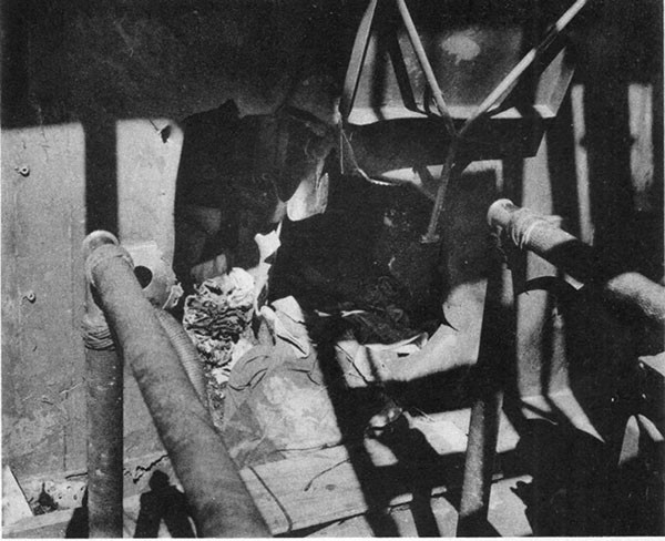
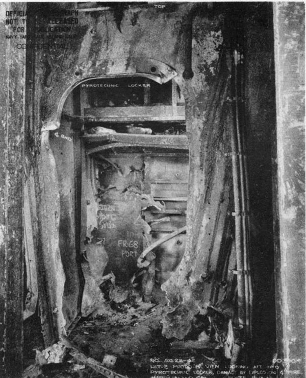
--32--
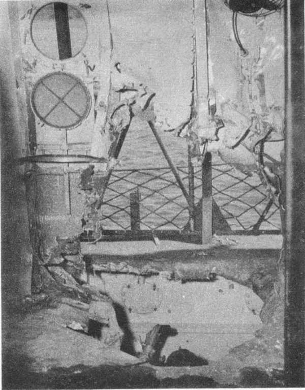
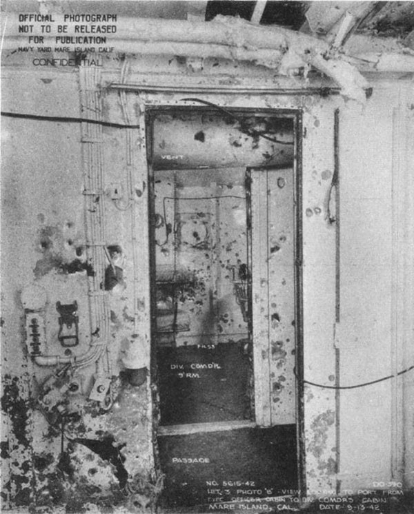
--33--
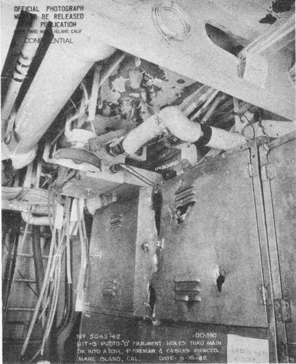
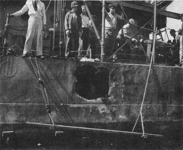
--34--
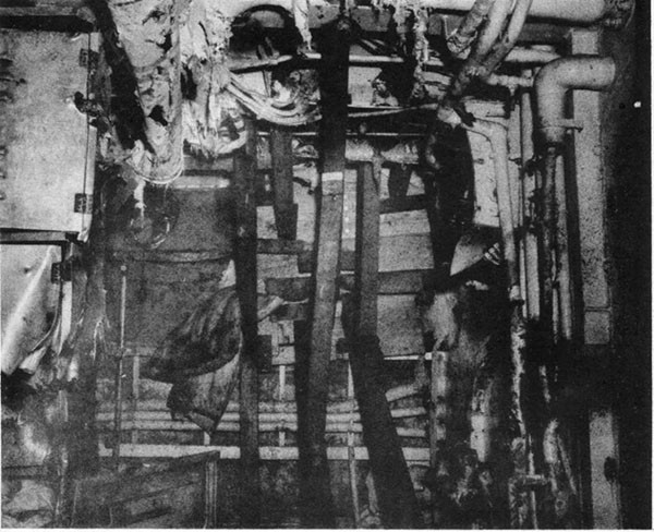
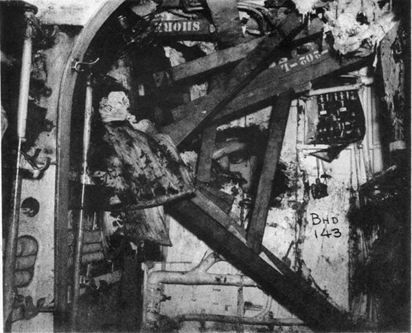
--35--
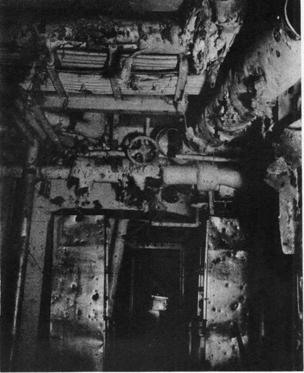
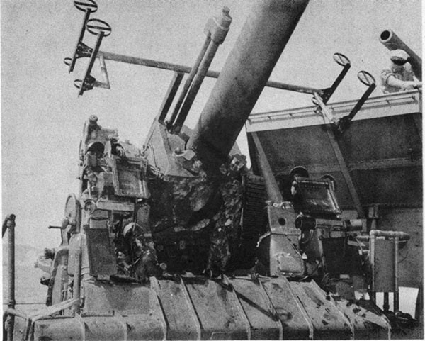
--36--
PLATE III
GUNFIRE DAMAGE
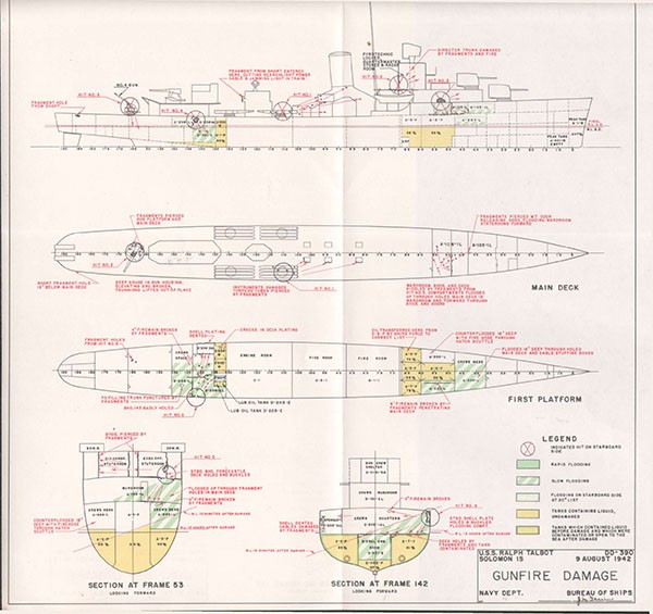
SECTION IV
U.S.S. JOHNSTON (DD557)
Loss in Action
Off Samar
25 October 1944
| Class | FLETCHER (DD445) | Length (O.A.) | 376 Ft. 6 In. |
| Commissioned | October 1943 | Beam (Extreme) | 39 Ft. 7 In. |
| Displacement | Draft (Estimated Mean Before Damage) | 12 Ft. 6 In. | |
| (Standard) | 2050 Tons | ||
| (Before Damage) | 2550 Tons |
References:
(a) Senior Surviving Officer, U.S.S. JOHNSTON ltr. DD557/A16-3, Serial 04 of 14 November 1944 (Action Report)
(b) Senior Surviving Officer, U.S.S. JOHNSTON ltr. A16-3/L11-1, Serial 01 of 10 November 1944 (Loss of Ship Report)
(c) Senior Surviving Officer, U.S.S. JOHNSTON ltr. A16-3, Serial 03 of 13 November 1944 (Damage Report)
(d) ComCarDiv 25 Special Action Report of 29 October 1944, Serial 00100
(e) United States Strategic Bombing Survey Interrogation #47 (Ex-V.Adm. Kurita, IJN) 17 October 1945
--37--
U.S.S. JOHNSTON (DD557)
4-1 On the morning of 25 October 1944, JOHNSTON, with GAMBIER BAY (CVE73), HOEL (DD533) and SAMUEL B. ROBERTS (DE413), was sunk by gunfire in a memorable action which resulted in an overwhelming enemy force turning back from the strongest effort which the Japanese made to break up our invasion of the Philippines. The performance of the two destroyers from a damage control standpoint was remarkable. The excellent reports submitted by the senior surviving officer of JOHNSTON, her gunnery officer, are the basis for this analysis. Reference (e), a report of an interrogation of the commander of the opposing enemy force, provided some interesting background.
4-2 Our Task Unit 77.4.3, operating support aircraft for the landing operations in Leyte Gulf, was composed of 6 CVE's, 3 DD's, and 4 DE's. While on station east of Samar at about 0650, 25 October 1944, contact was made with a strong enemy force after its emergence from San Bernardino Straits. The sea was calm, the wind about 8 knots northeast and the sky partly cloudy with scattered squalls. The enemy force was comprised of four battleships, including YAMATO, six heavy cruisers and two squadrons of destroyers. Proceeding on a southwesterly course, the Japanese bore about 345 degrees (T), 17 miles distant from our force when JOHNSTON made contact. The enemy immediately deployed on course 110 degrees, opened fire on the U.S. carriers and began to close the range rapidly, at the same time endeavoring to keep to windward to head off the carriers which had taken an easterly course to launch planes. About 0710 the carriers, in circular formation, executed ships right to a southwesterly course, meantime zigzagging at 19 knots as they "chased" salvoes. Enemy heavy units were overtaking on the port quarter while his light units attacked on the starboard quarter.
4-3 Immediately after contact, JOHNSTON initiated defensive action, laying an effective funnel and FS smoke-screen. About 0720, employing the cover of her own smoke screen, she closed the leading enemy cruiser to within 9,000 yards and attacked with all torpedoes and the entire 5-inch battery. As JOHNSTON retired, she was struck by 6 projectiles almost simultaneously, disabling the after propulsion plant and the gyro and cutting all power to the after guns and steering gear. Numerous electrical fires ensued and slow flooding commenced in C-303-M, C-202-E and the after fireroom and after engineroom. Water also found its way into C-203-L through a hole in the main deck during sharp right turns. Speed was limited to 350 RPM on one engine (reportedly 17 knots). About 0730, a heavy rain squall gave the ship a ten-minute respite which permitted accomplishment of vital damage control measures.
4-4 For the next hour and a half JOHNSTON continuously engaged the enemy van at ranges between 6,000 and 12,000 yards, using radical maneuvers, smoke and a heavy volume of fire to confuse and break up cruiser and destroyer attacks on our carriers. During this period several projectile hits of minor consequence were received.
4-5 About 0910 three projectile hits forward caused potentially serious fires and loss of communications. Conn was shifted aft and until about 0940 the captain conned the ship from the fantail. During this time, hits were received throughout the length of the ship. By 0940 hits in way of the forward fireroom finally immobilized JOHNSTON. Since the enemy was closing rapidly, all watertight doors in the forward end of the ship were opened to expedite sinking and the ship was abandoned. About 1010 JOHNSTON's bow went under, she rolled over and then plunged. No records were saved. About 50 per cent of the ship's company,
--38--
including the damage control officer, the communications officer and the captain's recorder were rescued some fifty hours later by our own forces. About a third of those who abandoned ship perished in the water.
4-6 The armament of the ships firing on JOHNSTON included virtually every caliber of Japanese naval gun as indicated in the tabulation below:
| Caliber | Max. Range | Ship |
| 18.1 in. (46 cm) | 40,000 yds. | YAMATO |
| 16 in. | 36,000 yds. | NAGATO |
| 14 in. | 34,000 yds. | KONGO, HARUNA |
| 7.87 in. (20 cm) | 31,100 yds. | All CAs |
| 6.1 in. (15.5 cm) | 20,000 yds. | YAMATO |
| 6.0 in. (15 cm) | 20,000 yds. | KONGO, HARUNA |
| 5.5 in. (14 cm) | 18,000 yds. | NAGATO |
| 5 in. (12.7 cm) | 19,400 yds. | YAMATO, All CA's and some DD's |
| 4 in. (10 cm) | -- | TERUTSUKI DD's |
Projectiles in the lower half of the table usually were impact fuzed whereas those from 7.87 inches up, based on reports of other vessels simultaneously engaged, normally detonated at least 30 feet beyond impact unless they struck some object such as a gun mount or a heavy piece of machinery. Numerous projectiles passed all the way through both the destroyers and the escort carriers that day without detonating.
4-7 To facilitate the discussion of damage, the hits specifically identified have been numbered chronologically 1 to 13 as shown in Plate IV. Numerous other hits of lesser importance were suffered before the ship succumbed, but details are lacking on their effect.
4-8 Hits 1 to 3, occurring simultaneously about 0730, were reported by reference (a) to be a salvo of major caliber projectiles, 14-inch or larger. Coming from a relative bearing of about 190 degrees, these projectiles punctured the main deck at frames 156, 144, and 128 and detonated after impact with the after reduction gear, the after H.P. turbine and No. 4 boiler, respectively. Hit #1 punctured bulkheads 147 and 157 and caused flooding in C-202-E through a ruptured soil line sea chest and slow leakage into the after engineroom from the sea under the reduction gear foundation. Hit #2 cut the main steam line in several places before detonating. Fragments cut all the wireways on the port side leading aft through bulkhead 130-1/2. Hit #3 demolished No. 4 boiler and ruptured bulkhead 130-1/2 near the lower grating port side.
4-9 The shock of this salvo permanently disabled the gyro, the SC antenna and the dredger hoists to mounts Nos. 3 and 4. It became necessary to open doors and hatches and pass up ammunition by hand. C-303-M was reported to have flooded slowly so that one hour later water had reached a depth of six feet. The source of this flooding is not known. Possibly there was a rupture in the shell in way of the port stern tube due to whipping of the shaft, or near misses in the same salvo may have caused some unobserved underwater damage.
4-10 Hits 4, 5 and 6 were caused apparently by the secondary battery of the same enemy ship which scored Hits 1 to 3. Hit #4 was in way of No. 2 stack under the 40mm director sponsons. Its detonation on impact disabled both directors. Hits 5 and 6 struck the bridge port side, one detonated on impact and one passed through. The FD and SG radars were knocked out temporarily.
4-11 The identification of Hits 1 to 3 as 14-inch or larger by reference (a) is not convincing. The angle of fall through the ship of Hit #1 was
--39--
about 18 degrees and that of Hits 2 and 3 was greater. This represents a range of at least 21,000 yards from a 14-inch gun. The ships engaged by JOHNSTON after 0720 were estimated to be within 12,000 yards. In view of this and the localized extent of the damage, the projectiles involved were more probably the 7.87-inch from the main battery of a CA and Hits 4 to 6 are estimated to be 5-inch from the CA's secondary battery. Subsequent identified hits may have been any caliber under 8 inches judging from the location of detonation and extent of damage.
4-12 Hits 7, 8 and 9 occurred at intervals between 0730 and 0910. Hits 7 and 8 demolished the supply office and emergency radio, frames 104 to 110 main deck. Hit #9 struck forward of No. 3 5-inch gun. Although personnel casualties were heavy, these hits caused no vital damage.
4-13 Hits 10 to 12 occurred simultaneously about 0910. Hit #10 detonated in the coding room, frame 65, superstructure deck, wrecking all spaces on this level including radio central, 40mm clipping room and the passageway. An intense fire started in way of the 40mm clipping room and radio central. Hit #11 detonated in the No. 2 gun mount starting a fire in the upper handling room. The smoke of these fires forced evacuation of the bridge. Hit #12 struck just forward of No. 1 mount and was believed responsible for the flooding in way of the forward magazine.
4-14 The ship continued to maneuver and effectively employ its 5-inch battery until about 0940 when Hit #13 disabled the forward fireroom and opened holes that flooded this space. After JOHNSTON was dead in the water the enemy closed to 1,000 yards and riddled the hull with gunfire.
4-15 During the respite given by the rain squall after the first six hits, damage control measures began. The leak in the ruptured sea chest that was flooding C-202-E was stopped using tapered wooden plugs and rags. For reasons unknown the effort to supply casualty power from the forward board to the steering engineroom and to the after guns was unsuccessful. Repeated electrical fires started in the after engineering spaces as a result of this endeavor. Since flooding was taking place in the after engineroom a submersible pump was rigged using a casualty power cable spliced for additional length to reach the outlet in passage B-101-E. No power could be obtained on this connection either, so it was concluded that the casualty power connection on the forward board was faulty or damaged. All circuit breakers leading aft were left open thereafter and steering and operation of the after battery proceeded only by hand.
4-16 After the initial six hits, casualties from the bridge were promptly evacuated. Access to the injured personnel in the after engineering spaces, however, was obstructed by live steam bleeding from fractured piping. No. 3 upper handling room also filled with steam through the hatch at frame 148 which had been blown open by the blast. Repair party personnel entering these spaces wore asbestos suits and RBA.
4-17 Firefighting was very efficient. The numerous electrical fires after the first hits were successfully fought, being extinguished in about 30 minutes with CO2 portable units. The intense fires forward, after Hits 10 and 11, were promptly extinguished. Two hose streams and the sprinkling system were used on the fire in radio central and the clipping room and an additional hose stream was employed on No. 2 mount. Both fires forward were extinguished within 10 minutes.
4-18 At the start of action only two boilers were lighted off because the supply of fuel was very low. By 0720 all four boilers were cut in on the line and the plant was completely split. Following the disablement of the after plant, the ship maintained 350 RPM on the starboard shaft until about 0840 when there occurred a near collision with HEERMAN.
--40--
Reference (a) reported that this gave a speed of 17 knots. Even allowing for one propeller locked and dragging and for additional draft due to damage, 350 RPM should give 25 knots or greater. Since JOHNSTON continued to maneuver freely between two enemy groups each making 20 knots or better, the speed of 25 knots in JOHNSTON seems a reasonable assumption.
4-19 Vital services were not interfered with during the action except for the gyro casualty and the failure of casualty power aft. The precautions taken by ALBERT W. GRANT to facilitate employment of casualty power, as described in paragraph 5-47, might have eliminated this latter problem. Firemain pressure and power forward were apparently available until the very end. The ruggedness of radar, radio and I.C. gear was notable. TBS was reported still operable when the ship was abandoned. FD radar was used throughout for ranges although the antenna had to be grasped and elevated by hand after the shock of the first hits sheared the linkage for automatic control.
4-20 Reference (a) reported the master gyro frame "broken in half" due to the shock of Hits 1 to 6. Such a casualty is unique and open to some doubt. The critical mechanical features of the Mark 11 Sperry compass used in destroyers were the suspension wire and the suspension springs. These were designed to withstand a shock of 2000 foot pounds. The majority of gyro failures in battle in destroyers have been due to electrical damage. Mechanical failures have been infrequent except where shock was so severe that it was generally disruptive to equipment in the same area. It should be noted, however, that this is true only for this particular design of compass.
4-21 But for the continued presence of the enemy after the ship was immobilized, it is likely that JOHNSTON could have survived. No uncontrolled fires were raging, no serious list had developed and the rate of flooding was slow enough to permit control if attention could have been given to the problem as in ALBERT W. GRANT. That the ship rolled over as she sank is readily explained by the extent of free surface both forward, where doors were left open to speed the sinking, and aft in way of the machinery spaces and the first platform deck.
4-22 Few destroyers in their battle performance have more completely capitalized their design features than JOHNSTON. That she was fought so effectively at such a critical time for over two hours after severe initial damage not only inspires deep admiration for her ship's company, but also considerable confidence in her design and construction.
--41--
PLATE IV
GUNFIRE DAMAGE
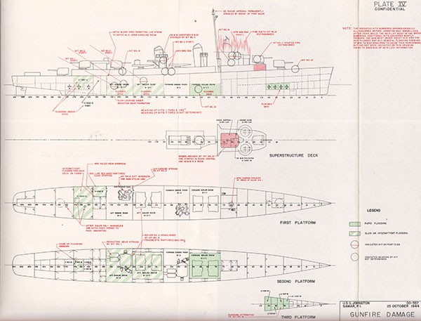
SECTION V
U.S.S. ALBERT W. GRANT (DD649)
Gunfire Damage Surigao Strait 25 October 1944
| Class | FLETCHER (DD445) | Length (O.A.) | 376 Ft. 6 In. |
| Commissioned | December 1943 | Beam (Extreme) | 39 Ft. 7 In. |
| Displacement | Draft (Mean, Before Damage) | 13" Ft. 8 In. | |
| (Standard) | 2050 Tons | ||
| (Before Damage) | 2925 Tons |
References:
(a) C.O. ALBERT W. GRANT ltr. DD649/A16-3, Serial 0106 of 11 November 1944 (Action Report)
(b) C.O. ALBERT W. GRANT ltr. DD649/A16-3, Serial 0107 of 14 November 1944 (War Damage Report)
(c) OINC Repair Unit 39 ltr. RU39/L11-1, Serial 265 of 20 November 1944 (Report of Repairs at Naval Base, Navy 3205)
(d) COMDT NYMI ltr. DD649/L11-1, Serial 360-718388 of 13 March 1945 (Report of Damage and Repairs at Navy Yard)
PHOTOGRAPHS 5-1 through 5-10 (Furnished by Repair Unit, Manus, and Navy Yard, Mare Island)
--42--
U.S.S. ALBERT W. GRANT (DD649)
5-1 In addition to the references, data for this report was obtained from informal interviews with her officers by representatives of the Bureau of Ships during her repairs at Mare Island.
5-2 During the Battle for Leyte Gulf on the night of October 24-25, ALBERT W. GRANT took part in a surface engagement which largely destroyed the Japanese Southern Force composed of battleships, cruisers and destroyers. GRANT sustained thirteen identified projectile hits, of which three apparently were 120mm Japanese and ten were 6-inch U.S. Loss of power, extensive flooding and a 9-degree list resulted. Strenuous damage control measures were carried out and the ship made her way, assisted part way by a tow, to the northern transport area for emergency repairs. The port shaft was operated to assist her tow from Leyte to Manus. After temporary repairs at Manus, she proceeded to Navy Yard, Mare Island, under her own power on one shaft. GRANT returned to service on 25 February 1945.
5-3 On the evening of 24 October 1944, in anticipation of an attempt by heavy Japanese naval units to force their entrance to Leyte Gulf through Surigao Strait from the south, battleships of the Seventh Fleet took station at the north end of the Strait while lighter units were deployed on either flank against the land masses to avoid radar detection. ALBERT W. GRANT was one of a force composed of 5 cruisers and Desron 56 assigned to the left or eastern flank. At 0333 on 25 October, after lying in wait for the enemy for several hours, Desron 56 was ordered to launch a torpedo attack on Japanese battleships proceeding north through the Strait. In three echelons of three each, these destroyers proceeded south, the first two echelons including GRANT, crossing the bows of our cruisers. After closing to a range of about 6,000 yards, they came right 90 degrees, delivered their attack and retired northward. Our cruisers opened fire about 0350. GRANT's first half salvo of torpedoes left the tubes at 0403 and the second at 0408. In the meantime salvoes from both sides began to straddle her. Just as GRANT began to turn north she was heavily hit.
5-4 Projectiles riddled the ship fore-and-aft. Fragments of a hit on 40mm mount No. 1 detonated some 40mm ready service ammunition and started a fire. Repeated hits on the topside damaged the boats, galley, radio room, forward stack and uptakes. The medical officer was killed and Repair II wiped out except for two badly wounded men. Additional hits occurred in the scullery, forward machinery spaces, after superstructure and an after berthing compartment. Power to the armament was completely interrupted. The battery remained operable manually except 5-inch gun No. 5 and 40mm mount No. 4, both of which were immobilized by fragments. Electric power was lost forward and all lighting except emergency circuits went out. All communications, including radio and radar, were reported inoperable. Steering control was shifted aft. The after turbo-generator was kept in operation, energizing some undamaged circuits. As GRANT retired, she commenced to lose speed. Surviving repair party personnel began to inspect damage.
5-5 The numerous hits occurred in such quick succession that their sequence was not observed, nor was it possible during the action to determine the true extent and nature of damage caused by each hit. The hits have arbitrarily been numbered from bow to stern below the main deck, and from bow to stern topside. Hits 1 to 6 and 8 to 10 have been identified as U.S. 6-inch AP projectiles containing a 2-pound explosive charge. Hit #7 was a U.S. 6-inch HC projectile.
--43--
5-6 Hit #1 penetrated the starboard side at frame 15 about 13 feet below the main deck (Photo 5-1). Its line of flight was aft and to port. The projectile left a 1 by 2-foot hole in the shell 14 inches above the second platform deck, passed through A-301-3A, tearing another 1 by 2-foot hole in bulkhead 18 and entered A-302-L. Here it deflected off two stanchions and glanced along the port shell plating before dropping unexploded to the deck. Forward light and power cables were severed and a vent duct torn. This dud is believed to have ricocheted off the water, as its path was slightly upward. Shortly after the action the projectile was recovered and jettisoned.
5-7 Hit #2 penetrated the starboard shell at frame 55 about 12 feet below the main deck (Photo 5-2). Its line of flight was aft and to port. The projectile left a 10-inch diameter hole in the shell plating 3 feet above the second platform, entered A-305-2AL, passed through the starboard longitudinal bulkhead of A-2-F at frame 62 (Photo 5-3) and then pierced athwartship bulkhead 65 and entered A-3-F. Here the projectile apparently broke up near the after port corner of the tank just above the second platform level. The tank top was bulged, jamming the computer and knocking switches open in the I.C. room on the first platform. A fragment of the projectile was found in A-305-2AL. Most of the fragments, however, pierced bulkheads 71 and 72, carrying through cofferdam A-4-V into the forward fireroom where they damaged the casing and air ducts of boiler No. 1 and severed vent ducts, auxiliary steam and exhaust lines, main feed piping, a salt-water cooling line, and several electric cables. The emergency feed pump, fire-and-bilge pump, blower No. 2 and a fuel oil strainer were also damaged by fragments of this projectile. One fragment was recovered from wing tank B-8-W which it pierced at frame 88.
5-8 Hit #3 penetrated the starboard shell at bulkhead 92-1/2 about 14 feet below the main deck. Its line of flight was aft and to port. The projectile left a 10 by 16-inch hole in the shell plating as it entered the forward engineroom. It glanced off the cross-over valve, penetrated the HP turbine foundation and entered the skirt of the LP turbine casing. Then it ricocheted off the inner (lower) casing of the LP turbine and passed down into the main condenser tube nest (Photo 5-5). The inner casing of this turbine was dented and torn, warping the third-stage diaphragm and causing the blades to rub. The cross-over valve and cruising turbine exhaust line were fractured, as well as electric cables, lube oil piping, vacuum-drag line and a recirculating line from the deaerating feed tank. The fragments recovered indicated that the shell broke up or detonated low order with virtually no explosive effect.
5-9 Hit #4 penetrated the juncture of the main deck and shell at frame 92, carrying aft and to port. The projectile left a hole roughly 2 feet in diameter at the point of entry and tore the upper corner of bulkhead 92-1/2 as it passed into the forward engineroom. Several pipe lines were damaged before it passed through the deaerating feed tank, wrecking the upper part of this tank and its internal fittings (Photos 5-6 and 5-7). The projectile then pierced bulkhead 110 and entered the after fireroom where it passed through the casing of boiler No. 3, glanced off a steam line, ricocheted off the inboard bulkhead of wing tank B-12-W and finally dropped to the floor plates without exploding. Numerous piping systems were cut or broken, including main steam, auxiliary steam, exhaust from HP to LP turbine, vacuum drag line and firemain. Electric cables, vent ducts and some piping were damaged. The nose cap was knocked from the projectile and found in the deaerating tank. The dud round was removed from the fireroom and jettisoned shortly after the action.
--44--
5-10 Hit #5 penetrated the starboard side at frame 95 about 30 inches below the main deck. The line of flight was also aft and to port. It left a hole roughly 10 inches in diameter in the shell plating as it entered the forward engineroom. Web frame 95-1/2 was fractured. The projectile passed through two stanchions, vent ducts, the main steam line, main feed line and glanced off the top of the deaerating tank. Then it entered the after fireroom through bulkhead 110, passed through the air duct and blower room B-3-2 and was stopped by the HP air compressor without exploding (Photo 5-8). The dud round was jettisoned shortly after the action.
5-11 Fragments from shorts left holes in the shell plating at four places on the port side, but did little other damage. Locations were at frame 12 about 7 feet below the main deck, frame 118 about 1 foot below the main deck, frame 167 about 2 feet below the main deck and frame 188 about 2 feet below the main deck.
5-12 Hit #6 ricocheted off the water as it approached from forward of the starboard beam. The projectile cut the outboard edge of the superstructure deck at frame 49 and tore through the splinter shield of 40mm mount No. 1 detonating some 40mm ready ammunition racked on this shield. It then penetrated the shield of 40mm mount No. 2 and cleared the ship without exploding.
5-13 Hit #7 struck a life raft and then entered the starboard side of the superstructure at frame 69 about 4 feet above the first superstructure deck. Passing aft and to port, the projectile penetrated door 01-72 and detonated just abaft the superstructure. The fragment pattern was dense and destructive, indicating a high order burst. The walkways, supports, mast, flag bag, decks, vegetable locker, 36-inch searchlight, smokestack, etc. were riddled. Several cables were cut, including radio, radar, fighting and running light circuits. The base plate of this projectile was recovered, definitely identifying it as a U.S. 6-inch HC (Mark 34) type containing 13.2 pounds of explosive.
5-14 Hit #8 (probably 6-inch) approached from 35 degrees relative, sheared off the forward starboard boat davit, nicked a stanchion and passed through the forward stack without exploding (Photo 5-9). Hit #9 (probably 6- inch) paralleled Hit #8. It wrecked the starboard whaleboat, passed through the stack and cleared the ship without exploding.
5-15 Hit #10 ricocheted off the main deck at frame 71 (starboard) continued aft and to port damaging the bridge ladder. The projectile passed through the vegetable locker, the uptakes and fan room B-102-AE (Photo 5-33). Vent set 1-88 was destroyed, together with its electric panel and the boat-winch power panel (Photo 5-34). The projectile emerged on the main deck at frame 91 to strike the boat winch against which it detonated. The winch was demolished, main deck indented and a section of the port bulwark blown out. Fragmentation was extensive, indicating a high order burst (Photo 5-10). A cone-shaped pattern of projectile fragments riddled the deckhouse, 40mm mount No. 4 and its ready service stowage. One fragment cut the sprinkling line in this stowage which caused minor flooding. The gun was jammed in train. Power cables to the gun, to the gear in the control room below and to one 36-inch searchlight were punctured.
5-16 Hit #11 struck a port life raft and then lodged in the port side of the superstructure about 3 feet above the first superstructure deck level. The projectile did not explode and was jettisoned after the action. Hit #12 exploded on contact with the bow of the port motor whaleboat. Fragments struck the port torpedo director, the bridge and the forward
--45--
stack. Hit #13 detonated on impact with empty 5-inch powder tanks stacked on the main deck at frame 190. Fragments shattered a fireplug and penetrated the splinter shield of No. 5 5-inch gun. The gun was immobilized. All three of these hits came from the engaged side. They are estimated to have been 120mm projectiles fitted with impact fuzes.
5-17 There were two topside hits of smaller caliber, both estimated to be 40mm. One struck a port life raft, then entered radio central - A-102-LAC, causing minor damage at frame 69. The other passed completely through the upper level of the after deckhouse from port to starboard at frame 152, cutting the firemain riser to the sprinkling system for the 40mm ready service stowage. Fragment damage which could not be associated with any of the foregoing hits, and therefore presumed to be from shorts exploding on contact with the water, was found to have left holes in the navigating bridge and after deckhouse. The forward torpedo mount, trained abeam, had the outer edges of the flanges on barrels 1 and 5 nicked either by fragments or projectiles which passed over the ship.
5-18 Immediately after the hits were received, a member of Repair III noticed steam escaping in way of the forward engineering spaces. He secured the main and auxiliary steam deck stops and the fuel oil quick-closing valve to the forward fireroom. This action probably saved the lives of personnel on watch in this fireroom who had taken cover in the water of the fireroom bilges. To restore communications, emergency wiring for sound-powered phones was quickly run from the bridge to the steering gear room and after engineroom. During the first few minutes after the hits, the damage control officer made a quick inspection of the ship. He determined that the shell was ruptured at and below the water-line, that no firemain pressure was available forward, that Repair II was wiped out and that there had been a fire on 40mm mount No. 1. This fire, which had broken out in the ready service ammunition, was smothered with a mattress by a member of the gun crew and then extinguished with CO2.
5-19 Repair I personnel rigged a hose jumper around the break to restore pressure on the firemain forward. Personnel of Repair III isolated the fractured fireplug aft, then assisted in rigging the jumper forward. The hole in the starboard side at frame 55 was plugged with a mattress by the watch from the Diesel generator room. The forward repair party shored a mattress patch over the hole at frame 15. Soundings indicated no flooding in the forward part of the ship at this time. Repair III found no flooding nor serious damage abaft the machinery spaces. Minor flooding in the 40mm ready service room in the superstructure was stopped by isolating fractured firemain risers. With this work underway, the damage control officer reported the situation to the bridge in person.
5-20 Meanwhile the engineer officer, who had been officer-of-the-deck when the damage was incurred, made an inspection of the disabled forward plant and then entered the abandoned after fireroom. Boilers 3 and 4 had been steaming untended for five minutes and the water level had risen out of sight in the gage glasses, without apparent harm to the after plant. He secured both boilers and steam pressure aft began to drop. By 0420 GRANT lay dead in the water. The after turbo-generator stopped and the emergency Diesel generator started up, furnishing lighting to the after part of the ship and power to the I.C. room and steering gear. Attempts to feed emergency power through the after main switchboard were prevented by short circuits, hence only the circuits on the emergency board could be energized. Since ventilation units for the after engineroom were then without power, this space overheated and had to be secured in about five minutes.
--46--
5-21 A request for a tow was transmitted by blinker tube. Efforts were then concentrated on restoring No. 4 boiler to operation. No. 3 air casing had been damaged and steam continued to enter the after fireroom through holes in bulkhead 110 making the space almost untenable. Two dud 6-inch projectiles were removed from the lower gratings and jettisoned. At 0455 the Diesel generator cut out after running for 34 minutes. GRANT was now entirely without power. At 0505 No. 4 boiler was successfully lighted off, using a hand fuel oil pump. Preparations were then made for restoring the rest of the after plant to operation.
5-22 A short time after the action a report was received that in No. 3 upper handling room temperatures were rising. The temperature had risen above the 130-degree maximum of the thermometer due to the loss of ventilation and the proximity of the after engineroom. That part of the ready ammunition suspected of being overheated was jettisoned. Remaining ready service powder and projectiles were transferred to No. 4 upper handling room. In No. 3 magazine the temperature rose rapidly and all ammunition was transferred to No. 4 magazine where the temperature was normal. Other magazines were checked and Nos. 1 and 2 were secured because of flooding on the second platform forward.
5-23 The forward engineroom flooded at a moderate rate through the hole in the starboard side at frame 92-1/2. At a point about 3 feet below the original waterline, Hit #3 had opened both the engineroom and wing tank B-7-W to the sea. Water also entered the engineroom via the main injection and overboard discharge lines to the main condenser, leaking from smashed condenser tubes through the fractured turbine casing into the compartment. This was not discovered until three days after the action. Although the holes which Hits 1 and 2 had left in the starboard shell at frames 15 and 55 were originally above the waterline, some water entered these holes due to the bow wave and the motion of the ship. This leakage progressed in spite of the mattress patches and the holes in bulkhead 72 allowed slow flooding of the forward fireroom from A-305-2AL.
5-24 At 0543 NEWCOMB (DD586) came alongside to render assistance. Electric submersible pumps and gasoline handy-billies were loaned and medical and engineering personnel were sent over to replace casualties in GRANT. No. 4 boiler was soon thereafter cut in on the line enabling the after plant to supply power from the after turbo-generator. Casualty power was connected to five submersible pumps rigged in the machinery spaces. The forward main circulating pump could not be operated to take bilge suction because the auxiliary steam line had been fractured; however, the two after fire-and-bilge pumps were put in operation and an attempt was made to pump out the forward machinery spaces.
5-25 At 0640 NEWCOMB began to tow from alongside. The forward motion loosened the patches and leakage increased. The series of holes produced by Hit #2 inter-connected seven compartments forward and caused them to fill to the waterline. Leakage entering A-305-2AL at frame 55 progressed to A-305-1E through fume tight bulkhead 62 and fragment holes in the door. The openings in tanks A-2-F, A-3-F and A-4-V permitted oil to flow into the surrounding compartments and allowed the tanks to fill to the waterline. Holes in bulkhead 72 permitted water and oil from A-305-2AL to flood the forward fireroom to sea level. Wing tank B-8-W filled through a fragment hole from this fireroom. By 0730 the water in these compartments had nearly reached the first platform level.
5-26 Due to imminent air attack at 0808, NEWCOMB cast off and GRANT proceeded under her own power at about 6 knots on the port
--47--
shaft. The ship began to trim by the bow and list to port as flooding progressed. The hole in the shell from Hit #1 at frame 15 permitted flooding of A-301-1T, A-301-2A and A-301-3A. When the level in the latter reached about 2 feet above the deck, water spilled through the hole in bulkhead 18 into A-302-L. Then it entered A-405-C, presumably through the scuttle in the second platform deck and filled that compartment. The surface in A-302-L rose to about 6 feet above the second platform deck. In the forward engineroom the rising level combined with the port list brought the holes in bulkhead 110 to the water's edge and thereupon the after fireroom began to flood from the forward engineroom. The level in the fireroom rose to 5-1/2 feet, a little over the lower gratings.
5-27 At 0945 the port engine was stopped and GRANT lay to. The rate of flooding exceeded the pumping capacity. A minor switchboard fire occurred but did not interfere with the operation of submersible pumps. By 1008 the ship had listed 9 degrees to port and drafts had increased to 21 feet forward and 13 feet 8 inches aft.1 As a countermeasure the captain ordered the jettisoning of topside weights. Both anchors and chains, both boats, the boat winch, loading machine, some 5-inch ammunition, some 40mm and 20mm ammunition, topside ready boxes, the galley sink, three davits, the port torpedo director, 40mm director No. 2, a scuttlebutt, smoke generators, depth charges and arbors, towing hawser, shore power cable, some topside spare parts and miscellaneous wreckage were disposed of.
5-28 At 1021 R[ichard]. P. LEARY (DD664) came alongside to assist with pumping and damage control. Efforts at patching and shoring were renewed. Mattress patches were shored in place over the holes in bulkhead 110. The after fireroom was then readily pumped out. About 1100 an oil fire which broke out amidship was extinguished promptly with fog. The ship's carpenter made a soft patch to cover the hole in bulkhead 18. All available handy-billies were then used to pump compartment A-302-L. The removal of weight forward corrected some of the trim. After 1245 the damage control efforts began to gain on the flooding and the ship was considered out of immediate danger.
5-29 At 1357 CHICKASAW (ATF83) came alongside to port and rendered immediate assistance in rigging patches and pumping. R. P. LEARY cast off. Salvage personnel fitted caisson-type patches over the holes in the shell at frames 15, 55, 92-1/2 and 95 and plugged small fragment holes with tapered wooden plugs. The two 6-inch gasoline-driven salvage pumps of CHICKASAW were then able, aided by GRANT's pumping facilities, to dewater each flooded space successively except for the forward engineroom. This reduced the port list to 4 degrees. About 1820 the tug began towing the destroyer toward the northern transport area in Leyte Gulf. GRANT exercised steering control from the bridge via the emergency telephone rig.
5-30 GRANT remained at anchor until 30 October making emergency repairs with her own force while CHICKASAW and CABLE (ARS19) continued pumping and salvage work. The forward "engineroom sea valves on the scoop injection, main circulating pump injection, main condenser overboard discharge and main lubricating oil cooler overboard discharge lines were closed by divers. These lines all connected into the salt water side of the main condenser, hence permitted flooding into the compartment through the ruptured LP turbine casing. The forward engineroom was then readily pumped out and the ship returned to an even keel.
5-31 When normal draft was restored, steel plate patches were welded over all holes in the hull except the one at frame 92. As the latter was below the waterline, a concrete backing was poured behind
__________
1 See paragraph 5-39
--48--
the shell to reinforce the caisson patch. As soon as flooded machinery spaces could be re-entered, steps were taken to flush out and preserve machinery and to flush and bake out electrical equipment to prevent deterioration pending permanent repairs. Piping and electrical repairs were undertaken to restore the distilling plant to operation. Five motors for this plant were recovered by washing with carbon tetrachloride and baking in the ship's ovens.
5-32 The casualty power system was extended to operate the 40mm installations, main and auxiliary radio, ship's lighting, interior communications, galley ranges, ovens, refrigerating plant, evaporators, etc. Some ventilation sets were restored to operation. Temporary connections also provided power to the 5-inch battery, dredger hoists and the main battery director. Five-inch guns 1 and 2 were restored to full automatic control, while 5-inch guns 3 and 4 functioned in indicating control. Priority in rigging casualty power was given the 40mm mounts and then the 5-inch battery, as enemy planes were frequently overhead during this period. The full use of 40mm mounts Nos. 1, 2, 3 and 5 was regained. Jury repairs restored No. 4 to manual operation only.
5-33 While GRANT was in Leyte Gulf moored between the two salvage vessels, foul weather caused some hull damage from pounding; the shell was crushed in and ruptured in several places, fortunately above the waterline.
5-34 On 30 October GRANT proceeded to Manus for docking in tow of HIDATSA (ATF102), using her port engine and exercising full steering control. Boiler No. 4 was fed with water containing a salinity ranging from 2 to 5 grains. Frequent bottom blows and boiler compound kept salinity in the boiler below 16 grains. Alkalinity was maintained at .35 to .45 per cent, slightly higher than normal.
5-35 In the two weeks at Manus the shore-based Repair Unit and ARD20 accomplished essential structural, machinery and electrical repairs and preservation work prior to the homeward voyage. After a three weeks' voyage from Manus on one shaft, GRANT arrived at Navy Yard, Mare Island, where permanent repairs and numerous authorized alterations were undertaken. GRANT was again ready for sea on 25 February 1945.
5-36 It is not known whether the U.S. 6-inch projectiles that passed through the superstructure exploded beyond the ship or not. Hence they cannot be definitely classed as duds. The 6-inch AP projectile with a Mark 21 base fuze requires a minimum plate thickness of three-eighths of an inch to initiate fuze action. Four of the five hits below the main deck penetrated on impact heavier plating than this minimum and might have been expected to have produced high order detonations. Of these, two broke up with little if any explosive effect and two were outright duds. The failure of the fuzes is believed to have been due to moisture absorption, inasmuch as the program for the moisture-proofing of fuzes had not been completed at the time of the action.
5-37 Despite their failure to detonate and the resultant small amount of structural damage, the AP projectiles which struck GRANT accomplished one of their primary purposes: to destroy watertight integrity below the waterline. The penetration of successive boundaries and the consequent progressive flooding very nearly led to the loss of the ship.
5-38 That GRANT was not lost through capsizing or plunging by the bow is largely due to the fact that flooding was confined to those compartments originally opened up by the damage. For example, if flooding had progressed upward from A-305-2AL into the first platform spaces
--49--
above, capsizing was quite probable. The fact that no water entered a single undamaged compartment proved the excellence of GRANT's program for maintaining watertight integrity. It indicated that fittings and closures had been properly maintained, that compartment check-off lists had been properly prepared, and that the crew had been thoroughly indoctrinated in the setting of material conditions.
5-39 An analysis of GRANT's stability is confused by an apparent error in reading drafts after damage. The ship reported drafts before damage of 12 feet 8 inches forward and 14 feet 9 inches aft. The corresponding displacement is 2900 tons and the GM approximately 3.4 feet. After damage, in the worst condition, with a 9-degree port list, GRANT reported drafts of 21 feet forward and 17 feet 9 inches aft. This corresponds to a displacement of 4700 tons, which is 500 tons greater than the reported amount of flooding could have produced. Since the damage water was nearly all forward of amidships, the reported draft aft, 17 feet 9 inches, appears to be a typographical error or else a navigational draft. The reported amount of damage water adds up to 1300 tons. This would give a draft forward of 21 feet and aft of 13 feet 8 inches. These drafts are confirmed by high water marks in the flooded spaces.
5-40 GM computed on the basis of data given varied from about 3.4 feet prior to damage to 1.0 feet at the time of maximum flooding at which time the ship also reached its maximum list of 9 degrees to port. Later, as all flooded spaces except the forward engineroom were pumped out, the list diminished to 4 degrees. GM computed for this last condition was 2.3 feet. Since flooding was reported to be symmetrical, some explanation of the list is required. The liquid loading initially was such that an off-center moment of about 300 foot tons to port existed. This should have caused about a 2-degree list in the undamaged condition although such was not reported. As the flooding forward gradually increased after damage, the free surface effect reduced GM and the same off-center moment in the A tanks caused the list to increase gradually. With 1.0 foot GM this off-center moment would have listed the ship through 4-1/2 degrees. The other
4-1/2 degrees could probably be attributed to the failure of water to leak past the emergency generator room bulkhead at frame 62. This bulkhead while designed only as airtight was also effectively watertight at small heads and therefore caused the flooding between bulkhead 54 and 72 to add an appreciable off-center weight on the port side.
5-41 Sixty-one tons of material were jettisoned, producing a net gain in GM of 0.16 feet. The only sizable low weights removed were the two anchor chains. These totalled 11 tons, but being only 3.4 feet below the center of gravity they produced a negligible reduction in GM. However, their removal did assist slightly in improving the bow trim. The total effect on trim of jettisoning the entire 61 tons was to aggravate the bow trim about 2 inches. The decision to jettison topside weights was well taken, since the flooding appeared to be out of hand. However, only those weights which were readily removable, or which had been damaged in the action, had been jettisoned by the time the flooding was again brought under control. After patching bulkhead 18 and emptying compartment A-302-L, the ship was considered out of danger.
5-42 It was learned through interrogation of the ship's officers that GRANT, in common with various other destroyers, had made a practice of leaving about 18 inches of water in the bilges of all machinery spaces prior to an action. The purpose of this was to provide a means by which personnel could escape from scalding by ducking under water when a steam line carried away and it was stated that several men on watch in GRANT's forward fireroom were saved by going into the bilges until the steam stops were secured from topside. What their fate would have been if the valves had not been quickly secured - or if the ship had sunk - is not certain. From the standpoint of the survival of the ship, the carrying of loose water
--50--
in the bilges is hazardous for two reasons:
(1) If the space begins to flood, the presence of the water hastens the time when leaks will be covered and cannot be located and plugged.
(2) The free surface effect of water in the bilges seriously reduces stability and increases the danger of capsizing from extensive flooding elsewhere in the ship.
5-43 GRANT strongly recommended that an assortment of pre-fabricated patches be carried, both of the box or caisson type and the folding type of steel plate patch which can be inserted through the hole, opened out, and then anchored from the inside with a T-bolt and strongback. These are required in various sizes, ready for rigging and distribution throughout the ship in substantial numbers. The difficulty which GRANT encountered in attempting to keep hastily rigged mattress patches in place is common to the experience of other destroyers. To effectively patch a submerged hole, shallow-water diving apparatus has been needed and usually also the ship has had to lie to while diving was in progress. In this work GRANT used type JR battle lanterns successfully under water.
5-44 GRANT's experience proved that prompt plugging of interior holes is of primary importance in controlling flooding. If attention had been devoted earlier to the seating of patches over the holes in bulkheads 18, 72 and 110 before they became submerged, flooding would have been effectively restricted and the ship would have been in less jeopardy. As it was, repair parties attempted to control all damage at once, and working from the shell inward, lost control of the flooding because of leakage through interior boundaries. The damage control officer was of the opinion that velocity-power equipment would have been useful in patching interior boundaries. This equipment was on the allowance list, but had not yet been provided.
5-45 In addition to bilge pumps, portable electrical submersible pumps and 60 GPM gasoline handy-billies were used in dewatering operations prior to the arrival of the tug. Extra long leads of 100 feet had been previously installed on the electric cables of the submersibles. The long leads were very useful in moving the pumps about. The prescribed allowance of gasoline for handy-billies (10 gallons) was inadequate. Each of these pumps used about one gallon of gasoline every 17 minutes. All gasoline pumps failed at a critical period from lack of fuel. All of these pumps worked well, but required the constant attention of a machinist's mate to keep them in operation. Of four pumps, only three could be kept in operation at one time, the other being cooled. An increased allowance of all types of portable pumps was recommended. Since that time the destroyer allowance has been modified to include five electric submersibles, two P-500 gasoline-driven pumps, one handy-billy and four portable eductors. Gasoline stowage in the inflammables locker has been increased to 60 gallons, the wartime allowance of gasoline. More fire buckets and red bulbs for flashlights were also suggested by GRANT. For several hours after the hits, lights could not be used topside because of the proximity of the enemy battle line.
5-46 Damage and engineering casualty control were complicated by the nature of personnel casualties. The electrical officer, an entire repair party and many engineering personnel were incapacitated. Of the electrical gang, the CEM, one EM1c and two fully qualified strikers were casualties. The difficulty of restoring the after power plant to operation was further aggravated by lack of ventilation and lighting in the machinery spaces.
--51--
Electrical repairs were impeded by the large percentage of electric cables which had not been adequately marked by the building yard, especially where they passed between compartments. During the critical hours in many cases it proved impossible to trace out individual systems.
5-47 The rigging of casualty power was greatly facilitated by the fact that the ship's force had installed a short lead at each main switchboard to a cut-out switch which eliminated connecting up casualty power cables to a hot switchboard under adverse conditions. This was in accordance with Enclosure (A) to BuShips letter S62-6(660j) EN28/A2-11 of 2 June 1944, paragraph 7. The speed of installing the casualty power cable was facilitated by installing lugs on the ends. (See BuShips drawing No. 9-S-5290-L). Over 200 feet of extra cable had been obtained by the ship prior to damage. All the extra cable was used and additional lengths borrowed from other ships. GRANT recommended that more and longer lengths of casualty power cable be included in the allowance lists. The ship had always carried a portable electric 440-volt AC triple-outlet manifold. This enabled hooking up three submersible pumps in one location and saved valuable time in getting the ship's pumps and borrowed pumps in operation.
5-48 The rigging of the emergency telephone line for conning the ship was timely. Prior to the action, the ship installed 4-plug telephone jack-boxes approximately one to every 20 frames on both sides of the main deck. Although this installation greatly facilitated running the emergency communication system from bridge to engineroom and steering gear, it is preferable that such emergency gear be kept portable. Provision in the repair lockers to meet such contingencies should be made. After damage, communication with repair parties in GRANT was by messenger only.
5-49 Portable battle lanterns had been previously installed in the wardroom which was used as the forward battle dressing station. Almost double the allowed quota of type JR battle lanterns was on board and all were used. Their usefulness even under water proved remarkable and the ship recommended the allowance be increased. The allowance was revised upward several times during the war. The present DD allowance of 119 type J1S lanterns plus 84 type JR-1 was established in November 1946 as a result of a comprehensive survey of requirements.
5-50 GRANT's reports emphasized that frequent drills in all types of damage control with junior personnel taking charge contributed much to her survival. The difficulties presented by her damage problems provided a number of lessons which the ship generously passed on for the benefit of others. Both the excellence of her damage control work and the completeness and candor of her subsequent reports were exceptional.
--52--
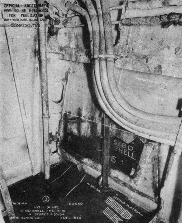
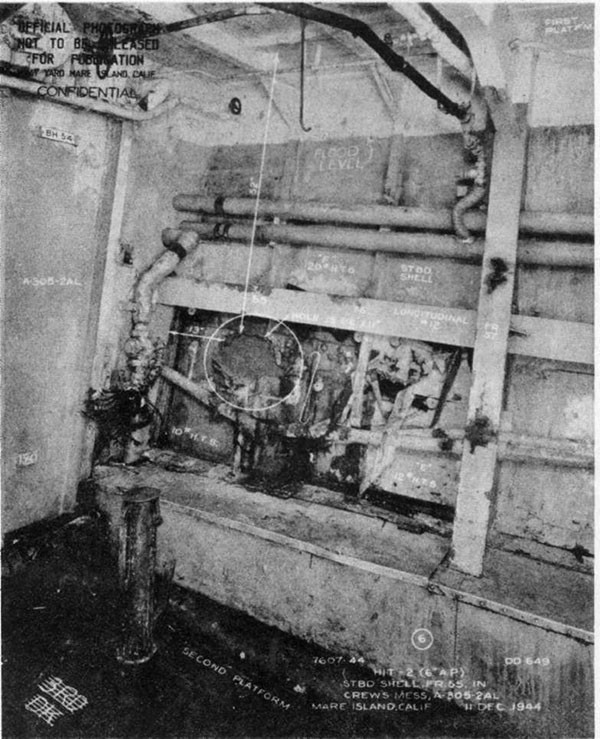
--53--
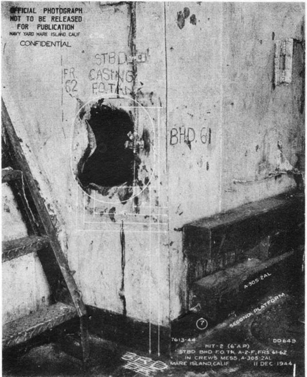
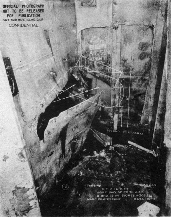
--54--
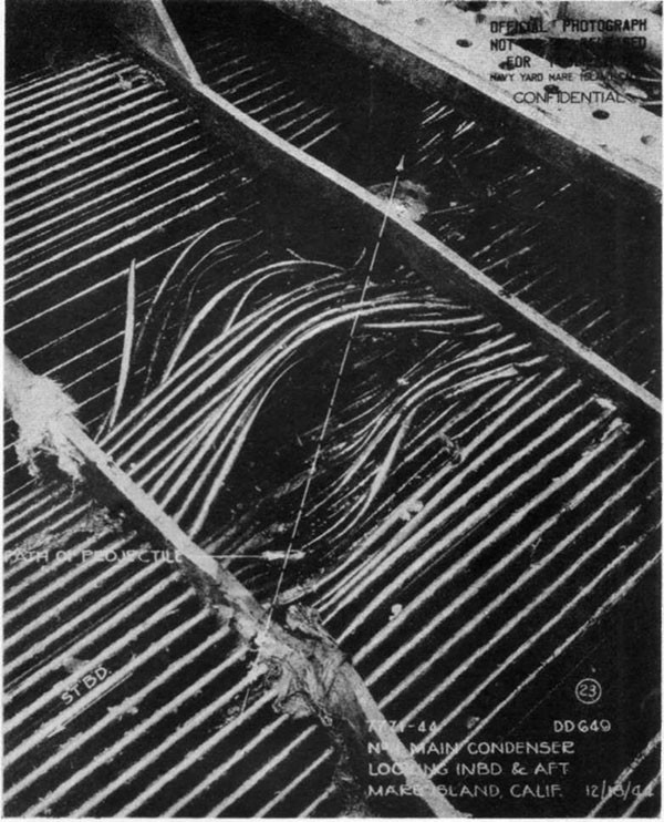
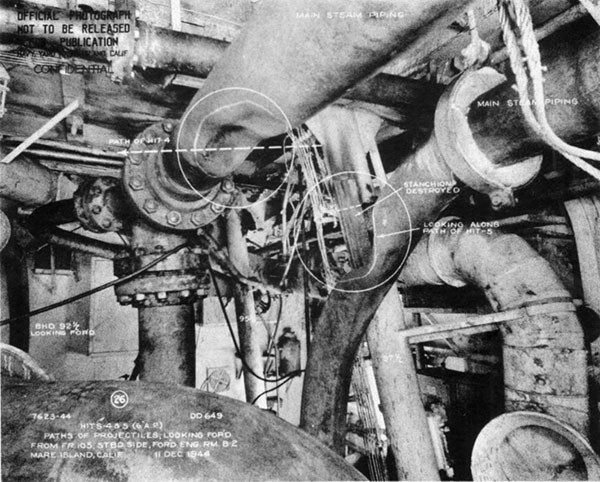
--55--
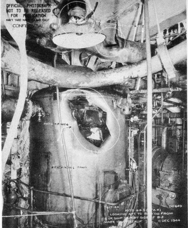
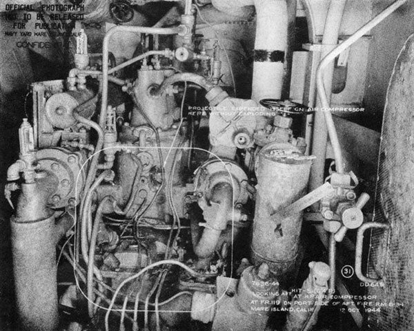
--56--
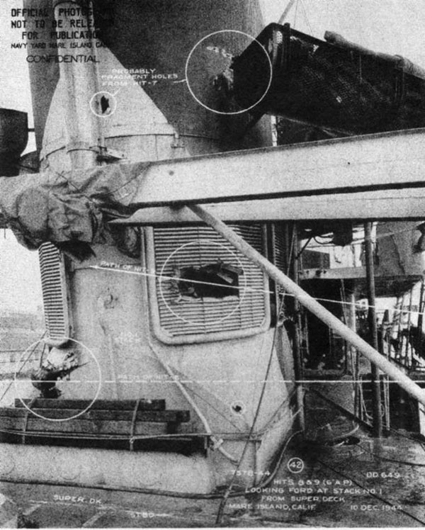
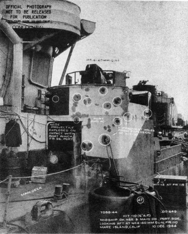
--57--
GUNFIRE DAMAGE
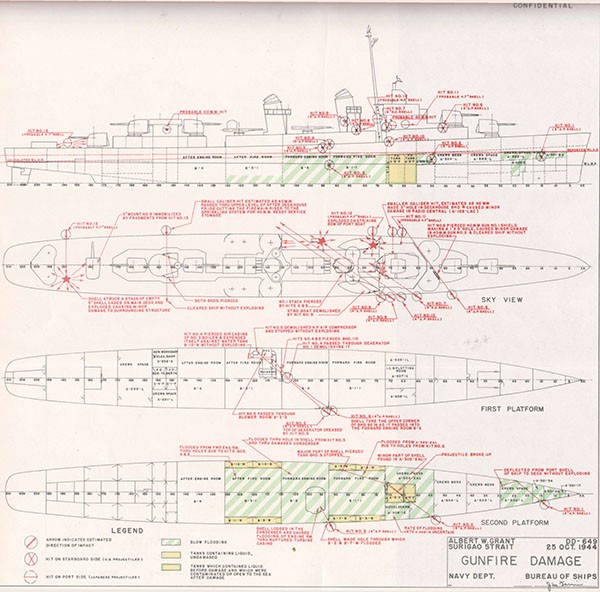
SECTION VI
U.S.S. AARON WARD (DD483)
Loss in Action
Off Guadalcanal
7 April 1943
| Class | BRISTOL (DD483) | Length (O.A.) | 348 Ft. 3 In. |
| Commissioned | March 1942 | Beam (Extreme) | 36 Ft. 0 In. |
| Displacement | Draft (Estimated Mean Before Damage) | 13 Ft. 0 In. | |
| (Standard) | 1630 Tons | ||
| (Before Damage) | 2380 Tons |
References:
(a) C.O. AARON WARD ltr. DD483/A16-3, Serial 0025 of 16 April 1943 (Action Report with endorsements)
(b) C.O. ORTOLAN ltr. ASR5/A4-3/A9 of 11 April 1943 (Action Report.
(c) VIREO (ATO144) War Diary for 7 April 1943
PLATE VI
NOTE: The ship discussed in this Section should not be confused with her successor, AARON WARD (DM34), photographs of which appear in SECTION II.
--58--
U.S.S. AARON WARD (DD483)
6-1 In the early afternoon of 7 April 1943, in anticipation of a Japanese air attack on shipping in the Tulagi-Guadalcanal area, AARON WARD was assigned as escort for LST449 which cleared the area, retiring to the eastward about two miles north of Guadalcanal. At 1508 AARON WARD, zigzagging at 20 knots, sighted dogfighting planes and commenced tracking an incoming group on the starboard hand. The sky was overcast with low clouds and the sea calm with a light breeze.
6-2 At 1512 three bombers dived through the clouds on the port quarter surprising the ship. As the battery swung to open fire, flank speed and full left rudder were ordered. Three bombs were dropped; one hit and detonated in the after engineroom port side, while two were close near misses which detonated underwater on the port side, one abreast each fireroom. Within the next minute a second similar attacking group scored two close near misses port side abreast the after engineroom.
6-3 All propulsive and electric power was lost immediately. The ship had no emergency Diesel generator. After the first pattern landed, a heavy flexural vibration occurred. This was attributed to the mining effect of the near misses, one of which, abreast the forward fireroom, was estimated to have detonated within five feet of the shell. Flooding to the waterline took place rapidly in both firerooms and in the after engineroom due to blast and fragment holes. List was negligible, but freeboard 15 minutes after the attack had decreased to about 6 inches amidships and one foot aft. The forward engineroom and the living compartment C-201-L just abaft the after engineroom flooded slowly. The blast of the hit deflected the main deck 10 inches upward over the after engineroom and knocked one torpedo forward in the tube so that the starting mechanism tripped. The torpedo jammed against the forward uptakes and ran hot, starting a minor fire. Some 40mm ammunition in the clipping room was detonated by fragment attack. Mistaking steam for smoke, the 40mm magazine and No. 3 lower handling room were sprinkled to a depth of 10 inches.
6-4 Fifteen minutes after the attack ORTOLAN (ASR5) reported to assist in salvage operations. Towing from ahead was undertaken and a 3-inch portable gasoline-driven salvage pump was loaned AARON WARD to try to control flooding in the forward engineroom. After approaching the Guadalcanal shore to a distance of 1,000 yards, AARON WARD requested the towing vessel to change course for Hutchinson Bay, 15 miles distant on the Tulagi side. Inspection indicated that up to this time all spaces above the first platform deck abaft bulkhead 147 were intact and dry. Above the first platform this bulkhead was shored, but no effort was made to lower the 4-foot water level in C-201-L. The quick-acting door 2-147-1 had leaked slightly, but shoring stopped the leakage. Fifteen feet of water (3 feet less than the draft) had entered the forward engineroom.
6-5 At 1610 VIREO (ATO144) came alongside to assist. The speed of the tow was increased to about 4 knots. At 1645 VIREO took suction with her 6-inch salvage pump on the forward engineroom. At 1850, owing to jack-knifing of the tow when a change of course was attempted, ORTOLAN stopped and later cast off the tow line. At 1925 towing was resumed at 3 knots, one tug alongside either side. By this time all topside depth charges had been safely jettisoned, a slight starboard list had been noted and the mean freeboard of the main deck was zero. Reference (a) reported 2 to 3 inches of water on the main deck over the machinery spaces and six inches of freeboard aft. About 2045, during a change of course, the starboard list began to increase steadily. Topside portable
--59--
gear was moved to port and forward in a futile effort to halt the increase. By 2100 the starboard list reached 9 degrees and the fantail had become awash. As the stern continued to settle it became evident that foundering was imminent. Before beaching could be accomplished, the ship listed to about 20 degrees to starboard and then plunged rapidly by the stern at 2135, the bow rising perpendicularly between the two towing vessels. The stem remained visible a few minutes, probably because the depth of water, 40 fathoms, was somewhat less than the length of the ship.
6-6 Positive identification of the type of bomb involved is not possible. An 18-inch diameter hole in the main deck was reported. The planes which attacked could carry four 63 Kg or one 250 Kg bomb as normally loaded. Each plane dropped only one bomb. In view of the effect of the hit and the closest near miss, it is reasonable to assume that the commonly employed 250 Kg SAP type with 133 pounds of explosive was used in this case. This bomb had a 12-inch diameter and could have left an entry hole roughly 18 inches in diameter. The effective radius of a near miss of this size bomb is such that it is likely that only the closest one of the four near misses caused appreciable damage.
6-7 Structural damage in this case is not known in detail and its extent therefore must be judged by secondary effects. The bomb blast in the after engineroom was at or close to the shell and apparently vented outboard opening a large hole in the shell in way of the underwater body. The fragment holes in the main deck and the upward deflection of 10 inches in that deck were incidental effects of lesser significance. Fragment and blast damage to bulkheads 122-1/2 and 139 due to the same hit appear to have caused the flooding of the adjacent compartments. The near miss abreast the forward fireroom near frame 80 port side was so close as to have at first been thought a hit. The blast punctured and dished-in the port shell permitting the fireroom to fill rapidly. It also produced the hull flexure which caused leakage around steam lines in bulkhead 86-1/2 and around the shaft gland in bulkhead 103, slowly filling the forward engineroom. Reference (a) reported that the ship sagged amidships and that the sagging increased progressively. Judging from the mean draft, the estimated freeboard at the stern and depth of water over the main deck amidships as reported by that reference, it is not apparent that the ship sagged appreciably nor did the manner of sinking indicate that structural failure amidships had started. In way of the after engineroom the shell plating was ruptured outwardly on the port side and probably was the cause for the ship's unruliness as a tow which was remarked upon in ORTOLAN's report of the same action.
6-8 The major factor in the loss of AARON WARD was the weight of flood water. Calculations based on data in reference (a), indicate that about 1680 tons of sea water were added within 15 minutes to an initial displacement of 2380 tons giving an after-damage displacement of about 4060 tons. Submerged to the crown of the main deck amidships, and with a mean draft of 19 feet 6 inches, the ship would have displaced 4150 tons, so only about 90 tons of reserve buoyancy remained in the hull when ORTOLAN commenced towing. This constituted only 5 per cent of the reserve buoyancy available before damage. It is surprising, therefore, that the ship stayed afloat as long as it did. The Commanding Officer suggested that the working of the ship as vessels alongside maneuvered her, combined with the increased head on the starboard door 2-147-1 as the starboard list increased, caused this door to give way suddenly. Four and a half feet of water in C-202-L if so flooded, or two additional feet in the slowly filling forward engineroom were enough to eliminate her small remaining reserve buoyancy. Apparently as the fantail became awash, rapid progressive flooding took place along the first platform aft, leading to the plunge by the stern.
--60--
6-9 The decision to proceed to the Tulagi shore rather than beach on Guadalcanal was primarily due to the consideration of protection from air attack. The error in judgment as to the ability of the ship to survive the longer tow appears to have been due to misplaced emphasis on an assumed satisfactory stability condition after rapid flooding had stopped. GM in a vessel of this class at about 4000 tons displacement, flooded between bulkheads 67 and 147, is approximately zero, but due to the calm water the loginess of the ship might not have been noticed especially since much of the free surface effect was broken up by overhead structure under the main deck.
6-10 The total weight of depth charges jettisoned was under 13 tons. No effort to jettison any other appreciable weights, such as 5-inch ammunition, torpedoes or torpedo mounts was reported. Shifting loose gear to counteract list was not only ineffective, but also hazardous with such an extensive free surface present. The alternative corrective measure was the removal of flood water. Some flood water which entered the forward mess compartment via a scupper drain was bailed out by a bucket brigade. But compartment C-201-L, which flooded slowly and which might possibly have been made tight and dewatered, was apparently surrendered without close investigation. The leaks into the forward engine-room through the forward bulkhead around the steam lines were accessible but apparently were not plugged.
6-11 Lack of an emergency Diesel generator to provide lighting and power for submersible pumps was a serious handicap. Obviously the damage to the machinery plant was beyond restoration by the ship's force.
6-12 The minor fire on the torpedo mount caused by the hot run of the torpedo was readily extinguished, although the means of accomplishment was not recorded. Since no power was then available, it is probable that CO2 or a handy-billy was used.
6-13 AARON WARD is another example of major battle damage, primarily involving flooding, which indicates that if a ship does not sink within a few minutes after damage she will probably survive for a period of several hours. During that period, if evidence of structural failure of the hull girder does not become apparent the ship's ultimate survival in virtually every case will be determined by whether control of flooding is established. The object lesson in the loss of AARON WARD is the critical nature of reserve buoyancy in an extensively flooded, but apparently stable, ship. A damaged ship with virtually zero mean freeboard requires prompt and radical measures to improve buoyancy. Removal of flood water is the best means. Dewatering is best begun at the periphery of damage, and spaces to be dewatered first require the plugging of holes in surrounding structure. Jettisoning, to be effective, has to be vigorous and ruthless and must involve weights of consequence. Where there is only a dubious prospect of halting progressive flooding and thereby retaining a safe margin of buoyancy or stability, the only alternative is beaching.
--61--
PLATE VI
BOMB DAMAGE
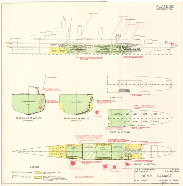
SECTION VII
U.S.S. MAYRANT (DD402)
Near-Miss Bomb Damage
Off Palermo
26 July 1943
| Class | BENHAM (DD397) | Length (O.A.) | 340 Ft. 9 In. |
| Commissioned | September 1939 | Beam (Extreme) | 35 Ft. 6 In. |
| Displacement | Draft (Estimated Mean, Before Damage) | 13 Ft. 4 In. | |
| (Standard) | 1500 Tons | ||
| (Before Damage) | 2380 Tons |
References:
(a) C.O. MAYRANT ltr. DD402/A16, Serial 055 of 23 August 1943 (Action Report)
(b) C.O. MAYRANT ltr. DD402/L11, Serial 058 of 23 August 1943 (War Damage Report)
(c) British Admiralty Delegation, Director of Naval Construction (W), ltr. of 16 March 1944 (Report of Damage and Temporary Repairs by Malta Yard)
(d) COMDT NYCHAS ltr. A7-3/DD397/L11-1 (M-1-12) of 16 February 1944
PHOTOGRAPHS 7-1 through 7-10 (Furnished by Malta Yard and Navy Yard, Charleston)
PLATE VII
--62--
U.S.S. MAYRANT (DD402)
7-1 During the forenoon of 26 July 1943 while patrolling off Palermo, Sicily, MAYRANT was subjected to a bombing attack by German aircraft. A near miss port side amidships caused unusually extensive damage. All four machinery spaces flooded and circumferential buckling seriously impaired the strength of the hull. The ship was towed into Palermo for emergency repairs by salvage personnel after which she was towed to Malta where essential hull strength was restored in dock and one machinery plant was placed in operating condition. MAYRANT then safely proceeded on her own power to Navy Yard, Charleston, where permanent repairs were completed in February 1944.
7-2 At the time of the attack, the weather was fair with a calm sea and excellent visibility. MAYRANT was one of four destroyers patrolling an area about 18 miles northeast of Palermo. At 0931, a group of planes later identified as JU88 medium bombers, was contacted by radar and almost immediately sighted. The ship opened fire with the two 5-inch ready guns and orders were given for flank speed and right rudder. MAYRANT started to accelerate and swing right as the attack developed from several different directions.
7-3 Ten or more bombs fell harmlessly in the water nearby. After completing about 50 degrees of her turn, a near miss struck close aboard to port. It detonated under water about 5 feet from the shell abreast the forward engineroom at frame 104. A muffled explosion and violent shock were experienced. Personnel were thrown heavily to the deck or against bulkheads. The ship heeled sharply to port. Neither flash nor flame was observed. Radar instruments were incapacitated by shock and the bracket supporting the gyro-repeater in the pilothouse was fractured. In the galley a small fire resulted but was quickly extinguished with CO2.
7-4 All propulsive and electric power was immediately lost. Within a few seconds, the emergency Diesel generator started. The director and 5-inch battery resumed operation on emergency power as did also the 40mm installation with the exception of the port 40mm director. Presumably one or more of its cables had been cut. Five minutes later, the Diesel generator stopped due to failure of the cooling system.
7-5 The after fireroom and forward engineroom flooded almost immediately. The after engineroom flooded to sea level in about ten minutes. The forward fireroom filled more slowly. By 0945, the level in this compartment was 4 feet below the waterline. The ship took a 4-degree starboard list, with about 1 foot of freeboard at the low side and amidships. Five gasoline handy-billies rigged in the forward fireroom controlled the water level at 4 feet below sea level. Repeated soundings indicated no leakage in any part of the ship except the four engineering spaces.
7-6 At 0953, recognizing the critical status of reserve buoyancy, the whaleboat was launched and all torpedoes, depth charges, loading machine, starboard anchor and numerous small items were jettisoned. Because further air attack was considered imminent, no ready-service ammunition was disposed of, but 5-inch and 40mm ammunition and depth charges were brought up from the magazines and thrown overboard. The starboard torpedo mount was prepared for jettisoning by cutting through the base with an acetylene torch but it was later decided to keep the mount aboard due to the satisfactory progress of salvage work.
--63--
7-7 Pumps and hose were transferred to MAYRANT by boat from WAINWRIGHT (DD419), RHIND (DD404), SKILL (AM115) and STRIVE (AM117). At 1046, STRIVE made fast to MAYRANT's port side and gave assistance. Electric power was supplied to the 5-inch and 40mm batteries and to the electric submersible pumps by running casualty power cables between the two vessels. STRIVE also supplied additional gasoline for the handy-billies. Seven portable submersible pumps were rigged to take suction on the forward fireroom. Approximately 7 handy-billies also were constantly operating. The level of flood water in the forward fireroom remained at about 4 feet below the ship's waterline. The starboard list seemed to vary between 3 and 4 degrees and freeboard remained about 12 inches on the low side amidships.
7-8 At 1115, STRIVE began towing from alongside, but could not maintain the course. SKILL then passed a line to MAYRANT and commenced towing from ahead while STRIVE assisted alongside. About noon, enemy planes made an attack on other ships in the area. MAYRANT fired on the planes with her 5-inch battery but was not under direct attack. Shortly afterward, SC693 made fast to the starboard side and rigged a hose from her fire-and-bilge pump to MAYRANT's forward fireroom. With this assistance MAYRANT was moored alongside a pier in Palermo harbor by about 1615.
7-9 Salvage operations were immediately commenced by S.S. W.R. CHAMBERLIN (later renamed U.S.S. TACKLE, ARS37). Six gasoline-driven salvage pumps with a combined capacity of 3000 tons per hour were secured on MAYRANT's topside and put in operation. An examination by divers revealed a major indentation extended from bulkhead 90-1/2 to bulkhead 118 (about 48 feet) port side and from keel to main deck (Photo 7-1). The maximum indentation of about 7 feet was resisted by stanchions, machinery and piping which were pushed inboard distances of from 1 to 4 feet. There were two large tears in the shell and numerous smaller ones. The tear along frame 101 was about 8 inches wide and 6 feet long (Photo 7-2). That at frame 109 was 2 to 3 feet wide and 13 feet around the girth. All holes in the shell were in way of the after fireroom and forward engineroom. Ruptures in way of wrinkled stiffeners and shell longitudinals on the port side of bulkheads 90-1/2 and 118 permitted flooding of the after engine-room and the forward fireroom. Buckling of plating and longitudinals extended across the main deck and down the starboard side (Photos 7-3 and 7-6). The keel was later found to be kinked upward 6 inches at frame 97.
7-10 Divers installed emergency patches which consisted of mattresses and large hair-felt pads secured in place by wood battens and bolts through the shell. After pumping down all machinery spaces, the ship was inclined about 15 degrees to starboard so that carpenters could build forms around the inside of the larger holes. Concrete poured in these forms made fairly watertight plugs (Photo 7-5). Both torpedo tubes, No. 3 5-inch gun, the searchlight and the 5-inch director were landed at Palermo. A few wrecked machinery items were also removed and a 6-inch salvage pump was mounted on the main deck (Photo 7-3). The port of Palermo was raided by enemy bombers during these operations. MAYRANT was not directly hit, but a nearby ammunition dump was struck, causing an explosion which threw fragments and rocks into the air. Many of these struck the ship causing extensive minor damage to the hull and topsides. Emergency repairs at Palermo were completed 9 August and MAYRANT, in tow astern of NARRAGANSETT, proceeded to the dockyard at Malta, a distance of about 100 miles.
--64--
7-11 During the tow to Malta, moderately heavy weather was encountered, causing the concrete patches to crack and leak. When the ship arrived at Malta the pumps were just able to keep ahead of the leakage. MAYRANT was drydocked long enough to weld small steel patches over all holes in the hull (Photo 7-4). She then relinquished the dry dock to SHUBRICK (DD639). Six weeks later MAYRANT was again drydocked. A large wrapper patch of ten-pound (1/4-inch) steel plate was welded over the area of maximum distortion. This wrapper was faired to the original shell and extended from frame 87 to 121 and from keel to main deck. It was stiffened by outboard longitudinals bracketed to the damaged structure. The space between this outer hull and the previously patched shell formed a watertight blister. Transverse strength was sufficiently restored by partial renewal of bulkhead 104-1/2 and by fitting a diagonal stanchion at frame 113-1/2.
7-12 Structural damage seriously impaired the strength of MAYRANT's hull girder. In addition to rupture and distortion on the port side, shell plating was wrinkled on the starboard side from keel to main deck opposite the hit. Bottom longitudinals on the starboard side were buckled and several were fractured. The main deck was creased on the starboard side and buckled on the port side. Some doubt existed as to the extent of repair that was essential. MAYRANT had received a copy of War Damage Report No. 28 on the loss of O'BRIEN (DD415) which analyzed longitudinal strength requirements in some detail. Study of the O'BRIEN report led to the decision, both in MAYRANT and SHUBRICK, to replace all wrinkled plating and buckled or fractured longitudinals in the starboard half of the ship girder (Photo 7-9). A portion of the keel was replaced and temporary longitudinal girders were welded on the port side of the main deck (Photo 7-10). This work, together with the wrapper patch on the port shell, constituted a thorough restoration of longitudinal strength and undoubtedly was essential to the safety of the ship during her homeward passage.
7-13 Machinery repairs accomplished at Malta enabled MAYRANT to make 23 knots on one shaft. Two 75 Kw Caterpillar Diesel generators from an Amphibious Battalion at Bizerte were mounted on the main deck to supply electric power. All but one of the Diesel salvage pumps installed at Palermo were removed. The remaining pump was installed in the forward engineroom. The starboard propeller was removed. Pig iron ballast was secured in the starboard bilges to offset a slight port list due to the added weight of new plating. Engineering and gunnery trials were conducted and the ship was found seaworthy for the return trip to the United States. While most of the work at Malta was performed by ship's force, due to strikes by yard workmen, essential technical assistance was given by the Royal Navy Constructor at Malta.
7-14 MAYRANT left Malta under her own power, arriving at Charleston Navy Yard on 15 December. Most of the trip was made at 20 knots. About 5 degrees left rudder was needed to steer a straight course, due to use of the port engine only. During the return passage the temporary repairs were subjected to the test of very heavy weather. Winds of forces as high as 10 Beaufort (whole gale) were recorded. The condition of the sea varied from 6 to 9 (7-1/2 to 15-foot waves) throughout a 42-hour period. Considerable working of ship structure was observed, but the only failure was a small crack that opened up in a portion of the distorted main deck plating. All welded repairs held and the ship arrived in excellent condition. The thoroughness with which strength was restored at Malta undoubtedly saved MAYRANT from breaking in two.
--65--
7-15 At Charleston Navy Yard, careful hull measurements and checking of roller path data indicated that the ship as a whole was not seriously deformed by either horizontal bowing or vertical sagging. Repairs, including the replacement of all distorted structure, were completed in about two months.
7-16 The Commanding Officer estimated the damage to have been caused by a 1000-pound bomb which detonated 8 to 10 feet below the surface and about 5 feet from the shell. Based on this estimate and the extent and nature of the damage, it is believed that the missile was a 500 Kg (1100 pounds) GP bomb, known to have been used by German aircraft against naval targets. Such a bomb contained about 500 pounds of explosive.
7-17 A stability analysis indicates that MAYRANT had a positive GM of about 0.6 feet, corresponding to 3590 tons displacement after flooding. The starboard list was caused by structure and machinery shifting to starboard. The inclining moment of the estimated shift of structure and machinery accounts for only about half the 4 degrees list. It is surmised that the balance was occasioned either by a slight off-center permeability in the engineering spaces or by a greater than computed reduction in GM. Wisely no attempt was made to transfer fuel to correct the list. The small list was not troublesome and the lowered stability made the creation of a transverse moment a hazardous undertaking. About 32 tons jettisoned from the topside produced a gain in GM of 0.1 foot. Removal of about 50 tons of low weight (ammunition from magazines) offset 0.07 foot of this gain. The net improvement in stability was inconsequential. The total weight jettisoned, about 82 tons, restored about 3-1/2 inches of freeboard, the equivalent of removing 2,900 cubic feet of flood water.
7-18 The control of flooding in the forward fireroom was an important step. This compartment was filling more slowly than the other. Seven 2-1/2-inch submersible pumps and seven handy-billies with a total capacity of about 1400 GPM held the level at four feet below sea level. The difficulty in attempting to pump out a compartment prior to plugging holes is thus apparent. On the other hand considerable hazards to personnel are involved in any effort to patch or plug holes under water while action is still imminent. The source of flooding in the forward fireroom was not reported, but examination in drydock revealed several small tears in bulkhead 90-1/2 near the bottom on the port side.
7-19 The Diesel generator failure was attributed to lack of cooling water. The possibility of a repetition of this casualty has been minimized by redesigning the cooling system, to provide priming pumps and vents to prevent loss of suction.
7-20 A study of this case concurrently with that of AARON WARD indicates several interesting points of similarity.
(a) In both ships a close near miss within about 5 feet of the ship caused heavy flexural vibration with major structural damage and extensive flooding.
(b) The obvious indication of the critical condition of the ship in each case was the extremely low freeboard.
(c) Although initial flooding included all four main engineering spaces, the resultant loss of stability was not fatal in either case, the loss of AARON WARD being due to progressive flooding of additional compartments.
--66--
(d) Both ships were probably saved from structural failure by the fortunate circumstance of being in the lee of a large land mass, where calm water prevailed during salvage operations.
(e) In both ships the total weight of items jettisoned had little effect on freeboard or stability characteristics.
(f) In both ships strenuous pumping efforts prior to plugging leaks scarcely kept abreast of slow flooding in one major compartment.
(g) Underwater damage caused both ships to be unwieldy tows requiring at least two towing vessels to control the course.
7-21 In the case of MAYRANT the more adequate salvage facilities available and the absence of progressive flooding proved a deciding factor in the ship's survival. The interim repairs both at Palermo and Malta were well executed and proved their adequacy in the heavy weather encountered on each leg of the homeward voyage.
--67--
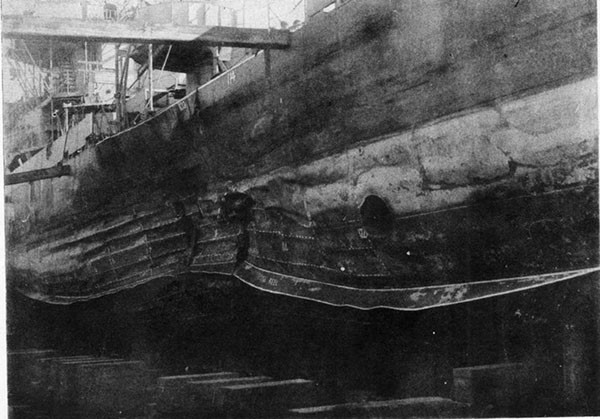
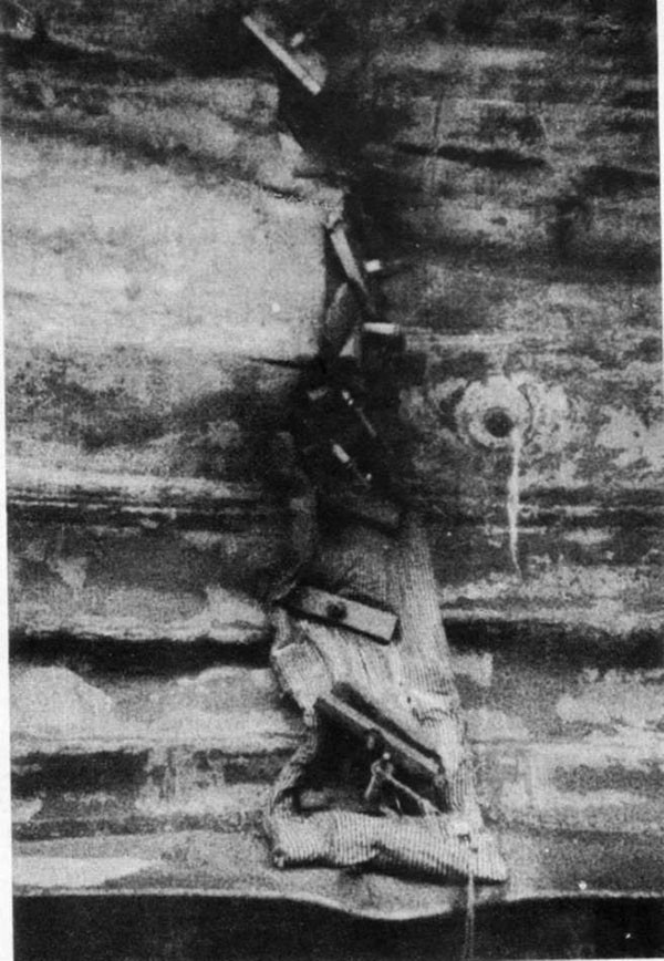
--68--
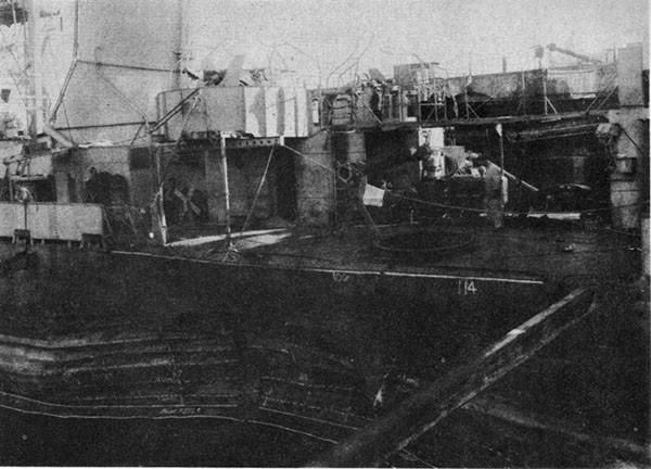
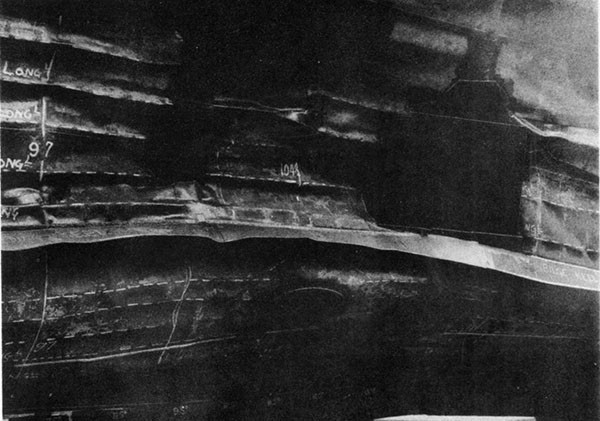
--69--
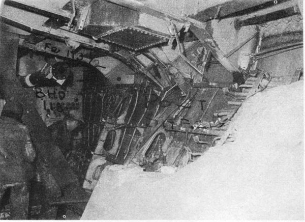
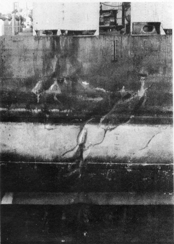
--70--
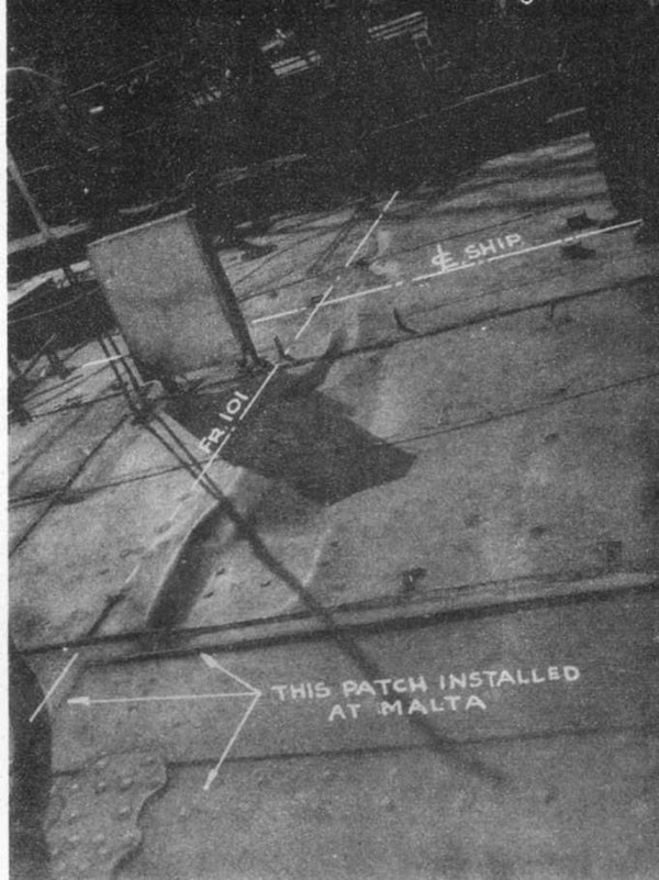
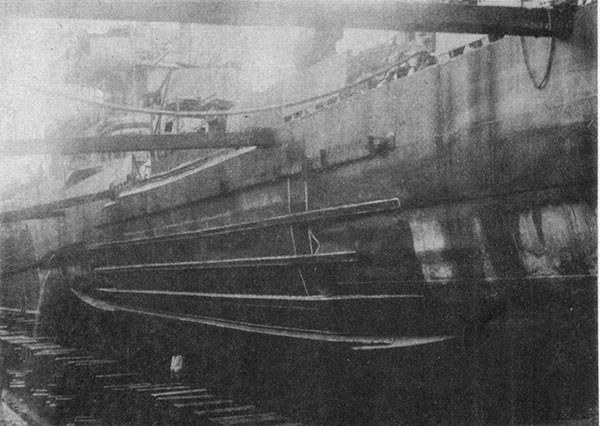
--71--
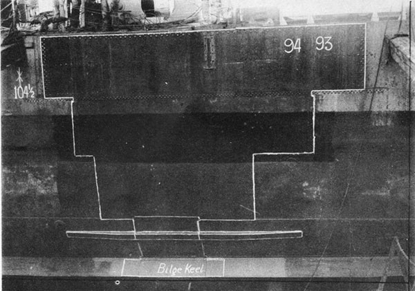
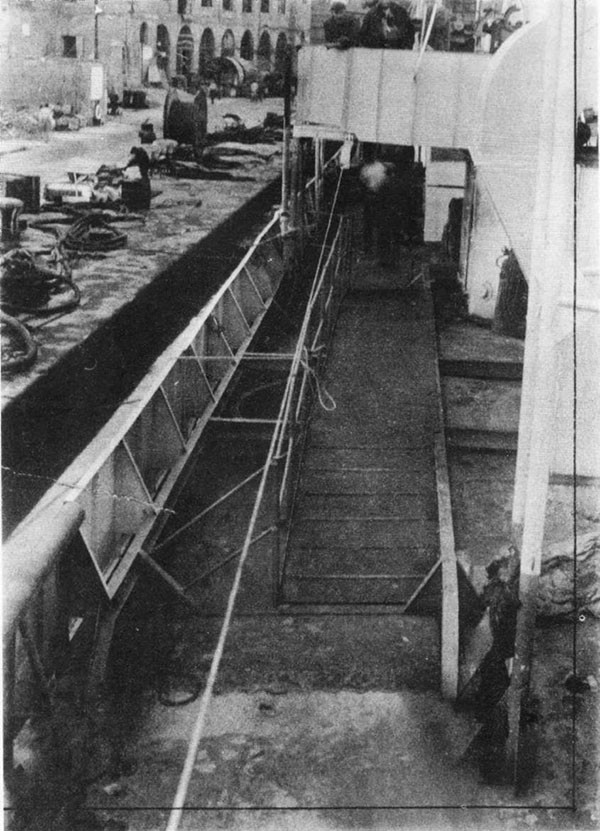
--72--
PLATE VII
BOMB DAMAGE
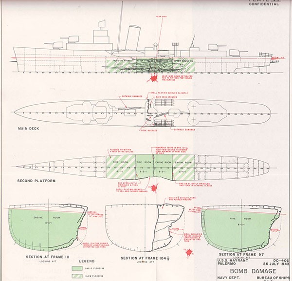
SECTION VIII
U.S.S. SHUBRICK (DD639)
Bomb Damage
Off Palermo
4 August 1943
| Class | BRISTOL (DD453) | Length (O.A.) | 348 Ft. 3 In. |
| Commissioned | February 1943 | Beam (Extreme) | 36 Ft. 1 In. |
| Displacement | Draft (Mean, Before Damage) | 13 Ft. 6 In. | |
| (Standard) | 1630 Tons | ||
| (Before Damage) | 2540 Tons |
References:
(a) C.O. SHUBRICK ltr. DD639/L11-1, Serial 031 of 15 September 1943 (War Damage Report)
(b) Director Naval Construction (W) British Admiralty Delegation ltr. No. S.R. 796/44 of 11 February 1944 (Temporary Repairs at Malta)
(c) COMDT NY NYK Damage Report of 18 October 1943
PHOTOGRAPHS 8-1 through 8-5 (Furnished by Malta Yard)
PLATE VIII
--73--
U.S.S. SHUBRICK (DD639)
8-1 While standing out of the harbor of Palermo during an air raid before dawn on the morning of 4 August 1943, SHUBRICK was struck by one of a pattern of three bombs. The hit passed through the after fireroom and detonated under the bottom, flooding two machinery spaces and disrupting all power. After 4 days at Palermo where emergency repairs were carried out, the ship was towed to Malta for drydocking. Upon completion of extensive structural repairs at Malta she proceeded to Navy Yard, New York under her own power on one shaft arriving 10 October 1943. Permanent repairs were completed on 6 December 1943.
8-2 The night of the action was clear and dark and a flat calm existed. At 0400 a surprise air attack began and SHUBRICK, in company with other U.S. Naval units, got under way and proceeded seaward at speeds of 5 to 10 knots. SHUBRICK's engineering plant was split and all four boilers were steaming. The low speed had been selected to avoid creating a conspicuous wake. About 0430, after reaching the outer harbor, the roar of a diving aircraft was heard and immediately thereafter a stick of three bombs landed, one short, one hit, one over. The attacking plane was never seen.
8-3 The near misses did no damage. The middle bomb, falling at an angle of 30 degrees to the vertical from starboard to port, struck the midship deckhouse at frame 101 about 3 feet to port of the centerline. It passed through the deckhouse top, the main deck, severed the auxiliary steam line in the after fireroom and penetrated all other obstructions encountered. Passing through the shell plating about 12 feet to port of the centerline, it detonated 5 or 6 feet below the ship under bulkhead 103 between the forward engineroom and after fireroom. A flexural vibration knocked personnel off their feet at the stern and jarred 5-inch gun No. 2 making it very difficult to train.
8-4 All propulsive and electric power was lost immediately due to ruptured steam lines. No Diesel generator was installed. The forward engineroom and after fireroom flooded rapidly, only two men surviving. Both these spaces were filled with steam from the ruptured auxiliary steam line and the damaged No. 3 boiler. Blackout curtains under the access hatches to the after fireroom hampered efforts to rescue survivors, most of whom died of steam burns. Deck control stops on main and auxiliary steam lines from boilers 1, 2 and 4 were secured from topside because steam leaks and flooding thwarted efforts to cross-connect the forward fireroom to the after engineroom. Valves on No. 3 boiler were jammed. Later it was found that the loss of feed water and the rupture of the only auxiliary exhaust line through bulkhead 103 prevented cross-connection even if the controlling valves had been accessible. Guns could be operated only in manual control. Light was furnished satisfactorily by Type JR-1 relay-controlled hand lanterns.
8-5 Draft increased 3 feet without list or trim. Flooding was confined to the two engineering spaces. Bulkhead 86-1/2, although slightly sprung, remained intact with negligible leakage. In bulkhead 122-1/2 some minor leaks through electric cable stuffing boxes were stopped with marlin. Shortly after the hit, "mousetrap" ammunition and seven 600-pound depth charges were jettisoned. A minesweeper towed SHUBRICK back to a pier at Palermo where she berthed at 0800.
8-6 At Palermo steps were immediately undertaken to restore ships service power. To operate the after 200 Kw turbo-generator and to
--74--
recover feed water, temporary steam, exhaust and condensate connections were run on deck to the forward fireroom. It was not attempted at Palermo to restore the piping required to operate the after main engines from the forward fireroom. Electrical grounds were located and jumper connections installed as necessary. Since the after generator supplied the shore-connection box, a temporary cable was run from this box to supply 440-volt power to the junction boxes at the break of the forecastle. From these boxes three leads were taken to the power panels in the galley passage, forward fireroom and forward messing space. A 110-volt supply line was run from the bus-tie in the after engineroom to the galley passage panel.
8-7 All torpedoes, the quintuple torpedo mount, torpedo director, depth charges, one anchor and chain and miscellaneous topside weights were removed. Bulkheads 86-1/2 and 122-1/2 were shored, the shores for the former being landed against a backing strip on the casing of No. 2 boiler. Before undertaking the trip to Malta the ship performed, with commendable enterprise, a rough inclining experiment at the pier side. One of the 5-inch guns was sighted at a fixed object on the beam. A whaleboat was then lifted from the water to list the ship. The gun was again sighted on the same object to measure the angle of list. The GM calculated from data so obtained was 1.5 feet approximately (see paragraph 8-19).
8-8 SHUBRICK was towed, without incident, using her own auxiliary plant, to Malta for drydocking. Inspection in dock showed that the hull had a shallow indentation from frame 94 to 113 (about 33 feet) extending from the keel to the port sheer strake (Photo 8-1). A hole in the shell, about 6 feet in diameter, was located at the center of the dent about 12 feet from the keel and directly under bulkhead 103 (Photo 8-2). Bulkhead plating and stiffeners were torn and folded upward on the port side, but the starboard half of bulkhead 103 was nearly intact. The keel had fractured through an improperly welded butt and deflected upward a maximum of about 5 inches. Less than half of the faying surface in the butt had been fused. Light buckling extended around the starboard shell plating opposite the hit, but was barely noticeable above the waterline. The main deck was intact except for the 2-foot by 3-foot hole through which the bomb passed (Photo 8-4).
8-9 The superheater and the tube nest on the port side of No. 3 boiler, No. 1 turbo-generator with its condenser, and the evaporators were wrecked. Forward main engines were damaged by shock and knocked out of alignment. Feed piping in way of reserve feed tanks was ruptured and lack of boiler water restricted use of the undamaged plant.
8-10 At Malta damaged HTS plates and longitudinals on the port side were replaced with medium steel of greater thickness (Photo 8-3). On the starboard side the wrinkled shell and longitudinals were reinforced externally (Photo 8-5). The damaged section of the keel and the port half of bulkhead 103 were replaced. The holes in the main deck and deckhouse top were covered with doubler plates.
8-11 Machinery repairs at Malta included flushing out all salvageable equipment in the flooded spaces with fresh water, drying with compressed air and slushing with lubricating oil for preservation. Piping was tested and repaired as required to operate the after engineroom from the forward fireroom. This included main steam, auxiliary steam, auxiliary exhaust, high and low pressure drains, fuel oil transfer, fire and flushing and the feed systems. The dented main steam crossover in the forward engineroom was tested, found satisfactory and reinstalled. In the
--75--
forward engineroom standby service was restored on the flushing pump, one fresh water pump and the main circulator (for bilge suction). In the after fireroom standby service was restored to the fire-and-bilge pump, emergency feed pump (for feed transfer) and fuel oil transfer pump. Since the shore water obtained at Palermo had a high chlorine content, only No. 1 boiler had been employed in the trip to Malta. During this time a 1/32-inch scale formed in the tubes of that boiler. At Malta this was cleaned out and no permanent damage to the boiler resulted.
8-12 With the assistance of dockyard facilities a 75 Kw 440-volt Diesel generator was installed as standby in the midship deckhouse. The emergency power cables installed at Palermo were left intact and additional jumpers were installed to repaired machinery units. Numerous flooded electric motors and controllers were flushed and baked out. Some damaged I.C. circuits to the after part of the ship were repaired by running jumpers from the panel in the I.C. room.
8-13 A Diesel oil-burning, portable distiller made available by the Army from captured German equipment was mounted on the main deck between midship and after deckhouses and was protected by installing a light sheet-metal housing. Temporary piping was run to supply this unit from the firemain and to carry the fresh water to the reserve feed tanks. Rated at 5,000 gallons, it produced an average of 4,000 gallons per day of 0.8 grains salinity.
8-14 Other repairs at Malta included removing the starboard propeller and stowing it on the main deck port side amidship. Eight tons of pig iron ballast were added in the port bilges of the forward engine-room to compensate for the removal of damaged machinery. Engineering and gunnery trials were conducted on 26 September. The ship recorded a speed of 23.5 knots at 250 RPM on the port shaft. It was noted at that speed that steam pressure dropped from 600 pounds per square inch at the forward boilers to 450 at the after throttle.
8-15 Fragments of the bomb that struck SHUBRICK were recovered and matched with a dud found in the dock at Malta. This served to identify the missile as a German 250 Kg (550-pound) GP bomb containing about 300 pounds of explosive. The detonation was estimated to have occurred 5 or 6 feet below the bottom (See Plate VIII).
8-16 With regard to material performance, the need of an emergency Diesel generator was evident. Although the 5-inch and 40mm batteries could still be operated manually without emergency power, their effectiveness was radically reduced. The alternate spacing of firerooms and enginerooms proved advantageous, even though cross-connection from the forward fireroom to the after engineroom could not be immediately accomplished. The vulnerability of the evaporator plant which was wrecked in this case has been lessened in later destroyer designs by installing a small auxiliary unit in the after engineroom. To eliminate blackout curtains in the machinery spaces in later classes of destroyers, at least one access to each machinery space has been provided from within a deckhouse passageway.
8-17 The main transverse bulkheads at frame 86-1/2 and 122-1/2 between SHUBRICK's engineering spaces deflected slightly but remained intact. Blast damage has frequently caused such bulkheads to take a permanent set, but they may be expected to withstand a head of water to the main deck unless the blast has initiated an actual rupture. Where shoring is considered necessary it will be most effective if landed on main structural members or foundations of heavy machinery. Shoring
--76--
against a boiler casing does not add greatly to the strength of a bulkhead. The casing is too light to give appreciable support and the boiler mounting, being designed for flexibility under heat expansion, may permit shores to work loose.
8-18 An analysis of structural strength after damage, made by the repair yard, indicated that about half the effective cross section of the hull girder had been destroyed. The section modulus in way of the damage was reduced to about two-thirds of its intact value above the neutral axis and to only about one-fifth its intact value below the neutral axis. The sagging load due to the flood water amidships raised the tensile stress at the bottom close to the yield point. If heavy weather had been encountered before arrival at Malta it is probable that progressive failure of the hull girder would have taken place in SHUBRICK.
8-19 The GM computed for the "as inclined" condition at Palermo erred 30 per cent on the conservative side. The correct calculation for GM would have given 2.2 feet using the same observed data. The computation of stability characteristics of a vessel in damaged condition is frequently a tricky problem and unless checked by personnel with considerable experience in such work may lead to erroneous conclusions although such was not the case with SHUBRICK. The effect on GM of the reported amount of flooding has been described in reference (c). This analysis indicates that before damage and with a displacement of 2510 tons, SHUBRICK's GM was 2.7 feet. With two machinery spaces flooded, the GM dropped to 1.9 feet with a displacement of 3320 tons. The removal of topside weights amounting to a total of 60 tons increased the metacentric height to a calculated value of 2.1 feet, which closely checks the value of 2.2 feet derived by the repair yard from the data of the ship's inclining experiment performed at Palermo. It is evident, therefore, that SHUBRICK was not in jeopardy so far as stability was concerned. The removal of topside weights was not immediately necessary. However, the material removed was nearly all recoverable and provided some desirable additional reserve buoyancy.
8-20 While SHUBRICK was not in critical danger after damage and while her repair personnel had relatively favorable conditions in which to work, every step taken was in the right direction and showed thorough understanding of the damage control problem as well as commendable execution of every important repair. To the thorough restoration of structural strength at Malta may be credited her safe passage home.
--77--
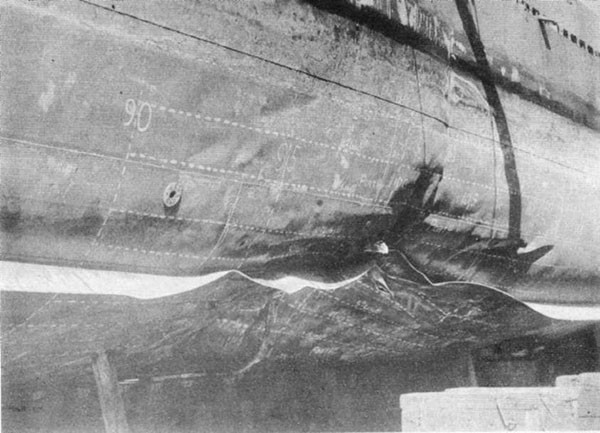
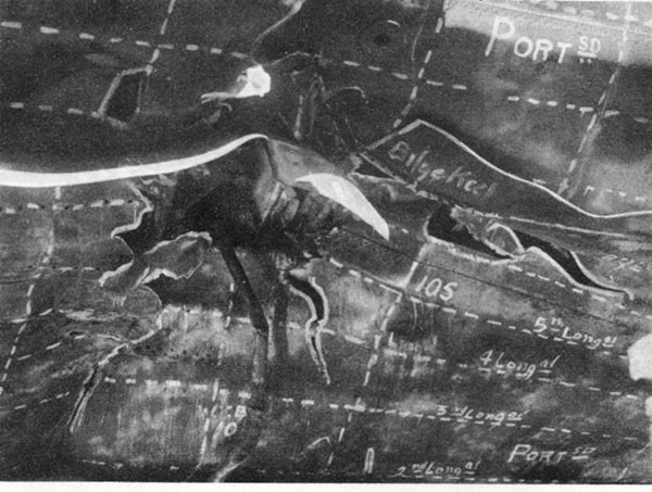
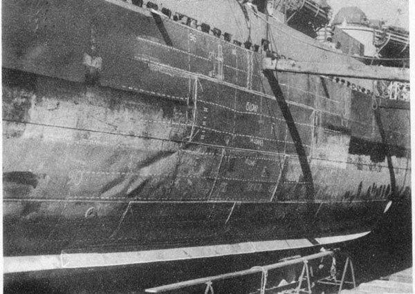
--78--
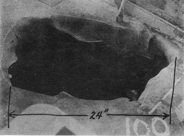
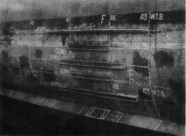
--79--
PLATE VIII
BOMB DAMAGE
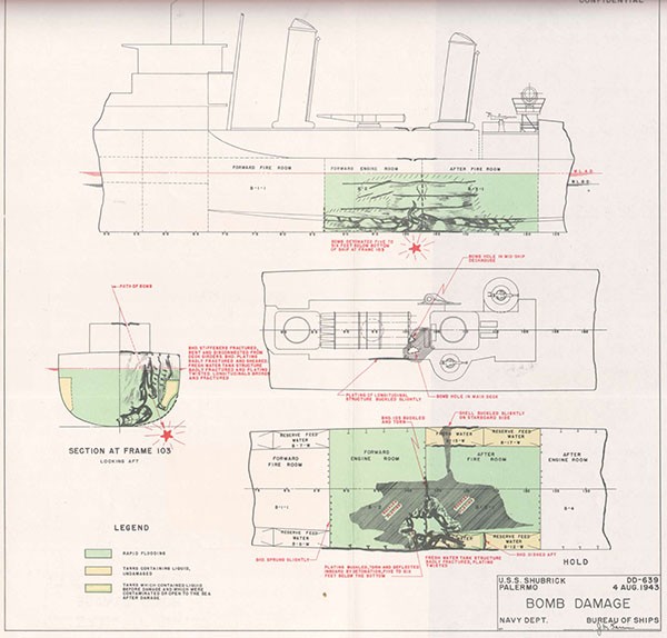
SECTION IX
U.S.S. BROWNSON (DD518)
Loss in Action
Off Cape Gloucester
26 December 1943
| Class | FLETCHER (DD445) | Length (O.A.) | 376 Ft. 6 In. |
| Commissioned | February 1943 | Beam (Extreme) | 39 Ft. 7 In. |
| Displacement | Draft (Mean, Before Damage) | 13 Ft. 9 In. | |
| (Standard) | 2050 Tons | ||
| (Before Damage) | 2950 Tons |
References:
(a) C.O. BROWNSON ltr. A15/DD518, Serial 008 of 4 January 1944 (Action Report)
(b) C.O. BROWNSON ltr. A9/DD518, Serial 009 of 6 January 1944 (War Damage Report
(c) COMDESRON 24 ltr A16-3, Serial 006 of 29 December 1943
(d) C.O. SHAW ltr DD373/A16, Serial 003 of 9 January 1944.
PHOTOGRAPHS 8-1 through 8-5 (Furnished by Malta Yard)
PLATE VIII
--80--
U.S.S. BROWNSON (DD518)
9-1 On 26 December 1943 while patrolling off Cape Gloucester, New Britain, in support of a landing operation, BROWNSON was bombed and sunk by Japanese dive bombers. SHAW (DD373) reported that "...BROWNSON was observed to receive direct bomb hits which caused a tremendous sheet of flame and resulted in clearing away everything above the main deck between the forward smoke pipe and No. 4, 5-inch, 38 caliber gun on the after deckhouse. About fifteen minutes later, the BROWNSON was seen to sink, after the midships section either broke in two or gave that effect by sinking below the surface first, to leave the bow and stern in the air and the last parts to go down."
9-2 At the time of the action, BROWNSON was patrolling on a northerly course at 15 knots in company with a group of destroyers. The weather was clear with bright sunshine; a cumulus cloud bank lay east and northeast. The sea was calm with a 5-knot northeast wind. At 1420 radar contact was made with "bogies" 60 miles distant and BROWNSON went to General Quarters, set condition AFFIRM, increased speed to 20 knots and cut in all boilers on the line. Incoming planes were tracked by radar until they were seen attacking ships to starboard. Attention of the bridge and director personnel was attracted to a Jap plane diving on the starboard beam. The plane released a bomb that threw up a large column of water about 50 yards abreast the bridge, rocking the ship without damage. Simultaneously a VAL surprised the ship on the port quarter. Automatic weapons opened fire and full left rudder was ordered. The plane was hit but continued in a 40-degree dive and released three bombs at about a 500-foot altitude, then apparently crashed clear of the ship. One large and one small bomb struck BROWNSON amidships. A second VAL with similar bomb load then scored a close near miss which detonated under the port quarter.
9-3 The point of impact of both hits was just abaft the after stack, slightly to starboard of the centerline. Passing downward and forward they apparently detonated simultaneously, one in the uptakes of the after stack and one in the tube nest of No. 3 boiler. Vessels nearby reported that a great flash of orange colored flame enveloped the after three-quarters of the ship. Survivors of BROWNSON reported that the blast and the ship's flexural vibration were abnormally severe. Personnel on the bridge were knocked down or tossed about; those on the main deck were thrown some distance along the deck. The bow and stern whipped like a springboard with a vertical amplitude of vibration estimated at 8 to 10 inches in the bow. A large amount of debris was hurled from the ship with great violence.
9-4 The midships deckhouse and all superstructure between the galley and No. 3 upper handling room were completely obliterated. The following structures and equipment were entirely carried away: main deck plating frames 86 to 135, the after stack and the top of the forward stack, the 36-inch searchlights with their platforms, both waist 40mm mounts with their directors and platforms, all amidships 20mm mounts, the after torpedo mount, the loading machine, K guns 2 and 4, the topmast, starboard yardarm and SC and SG radar antennas. The upper starboard shell plating was deflected outboard in way of the missing main deck and much of the sheer strake was missing. Flag bags were pushed forward and the after side of the forward superstructure was dished-in. The forward and after main transverse bulkheads of the after fireroom at frames 110 and 130-1/2 were demolished. Bulkhead 148 abaft the after engineroom was severely distorted and leaking and collapsed shortly after the hit. Bulkhead 157
--81--
was bulged aft below the second platform. The near miss on the port quarter tore away about 3 feet of the upper side plating, near frame 167 port. Survivors from the after end of the ship reported the main deck wash-boarded and the top of the after deckhouse buckled. Fragments riddled the after side of the forward stack, No. 3 gun shield and the port motor whaleboat. Door 1-137 in No. 3 upper handling room which normally opened forward, had been closed but blew aft into the handling room wrecking the center column of No. 3 gun.
9-5 Radar, fire control and ship control gear were immediately rendered inoperative although vacuum tubes were largely undamaged by the shock. Some sound power phones still functioned and the 5-inch guns 1, 2, 4 and 5 responded to an inquiry from control. Ordered to shift to local control manual operation, gun No. 4 reported jammed in train and No. 5 trained only with great difficulty. Automatic weapons forward and aft remained operable in hand drive. Part of the after torpedo mount landed on the fantail. The forward torpedo mount fell downward and aft into the galley. One warhead lodged in the base of the forward stack and another was noted adrift on the starboard side of the main deck. These warheads were both from the forward mount in which it was noted all after bodies with air flasks were intact.
9-6 In the after fireroom No. 3 boiler was demolished and the top of No. 4 was blown off. One man miraculously escaped from the forward engineroom with minor injuries. He had been on the lower level starting a condensate pump. Knocked down by the blast he ducked under the incoming water as much as possible to escape steam burns, finally floating up clear of the wreckage. There were no other survivors from the two enginerooms or after fireroom. The only machinery space not wrecked was the forward fireroom which was evacuated immediately after damage on the Captain's order. Personnel from this compartment reported the after bulkhead at frame 92-1/2 blown forward about a foot on the starboard side against No. 2 boiler. In the space just forward of this fireroom, the emergency Diesel generator started automatically when the explosion demolished the ship's service units and continued running until the ship sank.
9-7 Almost immediately after the explosion the ship took a list to starboard, estimated between 10 and 15 degrees, and two feet of water came over the starboard side amidships. About two feet of freeboard remained on the port side amidships.
9-8 Several small fires were promptly extinguished. One such fire, fed by leaking hydraulic oil, occurred in No. 3 upper handling room. Another had been initiated in the ready service ammunition at No. 5 40mm mount. Both were put out with CO2.. An attempt to sprinkle No. 3 magazine group was prevented by lack of firemain pressure, but this area is believed to have flooded from the sea soon after the hits. Due to open side doors in No. 3 gun shield, flame and blast from without were reported to have started a paint fire in the mount. Paint on the outside of the mount also burned.
9-9 By 1450 the bow had canted up 20 degrees or more with an equal amount of starboard list. The entire midbody was under water. Abandon ship was ordered, but a salvage party was left on the forecastle in the event the bow remained afloat. As the bow took a sudden additional list, however, this group was also ordered to abandon ship. After the midbody submerged, the stern raised to an angle of 35 degrees and then sank. The bow trimmed till it stood perpendicularly, submerged to the pilothouse, then slowly sank at about 1500, two minutes after the salvage party had left the ship.
--82--
9-10 Survivors were picked up promptly by accompanying vessels. Nine-tenths of BROWNSON's personnel had been equipped with Kapok life jackets which gave some protection against blast and fragments. They had also been instructed to swim on their backs which the majority were doing when an underwater explosion occurred. To the above factors may be credited the relatively small loss of life that resulted when, roughly two minutes after the stern submerged, the violent underwater explosion occurred presumably due to BROWNSON's depth charges. Several men swimming in the water were badly shaken and two were killed. DALY, picking up survivors at the time, reported that this explosion extinguished fires in her boilers, causing the loss of all power, and also threw her fire-control instruments out of alignment.
9-11 Based on the information that the attacking planes were VALs and that in several attacks on the same formation they employed three bombs, one large and two small, it is estimated that the BROWNSON was struck by one 250 Kg bomb either SAP or GP and one 63 Kg GP bomb.
9-12 The damage in BROWNSON obviously was much greater than could be attributed to the estimated 370 pounds of explosive contained in the two bombs which struck her. The Commanding Officer expressed the belief that torpedo air flasks exploded in the after mount and that both No. 3 and No. 4 boilers exploded. The unlikelihood of an explosion of express type boilers has already been explained in paragraph 2-64. The release of high pressure air from the ruptured flasks undoubtedly added to the severity of the blast. However, the extent of damage was many times greater than that which occurred in any confirmed case of an air flask explosion. The most plausible explanation is that one or more warheads in the after mount were detonated by fragment attack. If this surmise is a correct explanation of the cause of the unprecedented extent of bomb damage, BROWNSON's case is the only one in the recent war in which TNT loaded warheads were detonated by fragment attack. In DOWNES (DD375) at Pearl Harbor, it is probable that roasting due to an intense fire in the immediate vicinity caused a low order detonation of a warhead.
9-13 With respect to the depth charge detonation which apparently was the origin of the heavy underwater explosion after the ship sank, careful precautions against the accidental action of these charges had been taken. All charges except a ready pattern of eleven were customarily wired on safe with copper wire. The eleven charges in the ready pattern were customarily set on safe with safety forks in place and so kept until contacts were made. Immediately after the bombs hit, the chief torpedoman checked all depth charges except six 300-pound spares secured on the starboard side of the deck. These could not be reached due to debris and water covering them. He found that four 300 and three 600-pound charges had jarred to depth settings, parting the index-securing wires. These were set on safe with the wrench.
9-14 The loss of BROWNSON can be attributed to structural failure following the apparent detonation of one or more of her own torpedo warheads. It is clear that from the instant the damage occurred the condition of the ship was beyond the scope of damage control. As soon as structural failure became evident the loss of ship was a virtual certainty. The doctrine of keeping a salvage party aboard after the bulk of the crew has been evacuated is sound and in keeping with the best traditions, but the instability of an independent destroyer bow section makes the chance of its salvage extremely doubtful. The conduct of the ship's company under these circumstances cannot but arouse admiration.
--83--
PLATE IX
BOMB DAMAGE
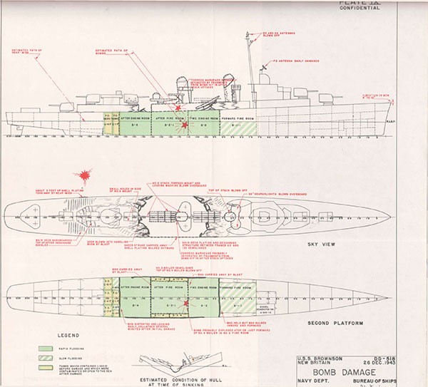
SECTION X
U.S.S. KILLEN (DD593)
Bomb Damage
Leyte Gulf
1 November 1944
| Class | FLETCHER (DD445) | Length (O.A.) | 376 Ft. 6 In. |
| Commissioned | May 1944 | Beam (Extreme) | 39 Ft. 7 In. |
| Displacement | Draft (Mean, Before Damage) | 13 Ft. 9 In. | |
| (Standard) | 2050 Tons | ||
| (Before Damage) | 2950 Tons |
References:
(a) C.O. KILLEN ltr. DD593/A9-3/A12/A16-3, Serial 0078 of 9 November 1944 (Action Report)
(b) C.O. KILLEN ltr. DD593/A9-8/A12/A16-3, Serial 080 of 19 November 1944 (Battle Damage Report)
(c) C.O. PIEDMONT ltr. AD17/L11-1, Serial 098 of 20 December 1944 (Report of Damage and Temporary Repairs)
PHOTOGRAPHS 10-1 through 10-8 (Furnished by C.O. PIEDMONT and C.O. ABSD-2)
PLATE X
--84--
U.S.S. KILLEN (DD593)
10-1 On the morning of 1 November 1944, while screening heavy ships of a support group in Leyte Gulf, KILLEN was repeatedly attacked by Japanese aircraft. The sixth plane dropped a bomb which pierced the shell on the port bow and detonated in No. 2 lower handling room. No magazine explosion resulted. Powder fires were extinguished by inrushing water. Other fires were brought under control promptly. KILLEN maintained station for about an hour after which flooding forced her to drop out of formation and proceed, repelling additional air attacks en route, to an anchorage in San Pedro Bay. There salvage personnel accomplished emergency repairs which permitted the ship to undertake the voyage to Manus for drydocking. After completion of repairs to the shell and sound gear in December, the homeward voyage was undertaken. Permanent repairs were completed at U.S. Naval Drydocks, Hunter's Point, in March 1945.
10-2 On the morning of the action, the sea was smooth with a light swell and light breeze. The sky was forty per cent obscured with cumulus clouds of considerable height. At 0930, while screening a force of battleships and cruisers, KILLEN received word that air attack was imminent. Material Condition ABLE was set and General Quarters stations were manned. At 0947 a poorly coordinated torpedo and dive bombing attack developed. KILLEN maintained station at 15 knots and then accelerated and maneuvered as she brought seven successive attackers under fire. The sixth plane, a VAL, dived through the clouds on the port bow, released a bomb at 500 feet and crashed into the sea off the starboard quarter.
10-3 This bomb penetrated the port side abreast No. 1 gun at the first platform level, passing down and aft through the second platform deck. It detonated about 14 feet beyond impact in the overhead of No. 2 lower handling room slightly below the waterline near the port shell, venting through a 6 by 10-foot hole blown in the shell in way of this compartment. Flooding trimmed the ship immediately several feet by the bow. The flash of the detonation was followed by yellow and then by black smoke. No flexural vibration was noted; shock was slight. The ship continued to maneuver at about 20 knots.
10-4 The extent of structural damage is best indicated by a study of PLATE X. In addition to the large hole opened in the port shell by the blast in the handling room, a two-foot diameter entry hole was opened in the shell at frame 33. This hole and two slightly larger openings where the first platform deck pulled away from the shell were at the level of the 20-foot waterline. These became awash at the maximum draft after damage. The collapse of doors and hatches in the area due to blast and the multiple perforation of successive boundaries by bomb fragments largely destroyed the watertight integrity between frames 18 and 72. The blast of the detonation obliterated the deck and overhead of the handling room A-409-M on the port side and the port halves of bulkheads 38 and 42 (Photo 10-2). Bulkheads 30 and 54, although deflected forward and aft respectively, were not extensively damaged above the second platform deck. On the third platform level and in the hold, structure as far removed as the bulkheads of the oil tanks between frames 54 and 65 was perforated by fragments.
10-5 All doors and hatches in the damaged area were jammed, sprung or bowed. Several were completely torn out; these included watertight doors 3-30, 3-42-1, 3-42-2, 3-54-1 and 3-54-2 on the second platform, 2-30 on the first platform and main deck hatches 1-18 and 1-38. The doors, of which half were a commercially patented CRS quick-acting type, failed by collapsing in the middle. On the individually-dogged types, the dogs pulled out (Photo 10-3).
--85--
10-6 Rapid flooding spread forward and aft along the second platform deck from bulkhead 18 to bulkhead 72 and was solid from the keel to the waterline from bulkhead 26 to 72. As KILLEN trimmed by the head, water rose about 6 feet above the second platform deck. Partial flooding took place in A-301-3A, A-404-A and A-405-C. Several fuel tanks in the forward group had been only about one-third full. Of these A-2-F, A-507-F and A-509-F holed by fragments, slowly filled. The sluice valve between A-2-F and A-3-F was open at the time. It is probable that the combination of fragment holes and open sluice valves interconnecting this group of tanks accounts for the contamination of fuel oil service to boilers 1 and 2 and also explains the 2-degree starboard list that resulted despite otherwise symmetrical flooding (See PLATE X).
10-7 The flash of the bomb's detonation, coming through open hatches in the decks, passed through No. 1 upper handling room on the first platform and entered No. 1 mount via the center column and No. 2 upper handling room via door 1-42 and the scuttle in the main deck. Most of these closures were open because No. 2 dredger hoist was out of commission and ammunition was being passed up by hand. Fire initiated in No. 2 lower handling room flashed through living compartments in the second platform, to CPO quarters, lower wardroom country and into No. 2 upper handling room. After the initial flash, yellowish smoke followed shortly by black smoke poured out of the hatches.
10-8 The two forward dredger hoists were severely distorted by the blast. The refrigerated spaces were demolished. The Diesel generator, ice machines, hot water pump and miscellaneous other equipment were damaged by submergence in water and oil. The firemain was cut at frame 44 by a fragment. All ventilation and electrical systems in the damaged area were disrupted by fragments, blast, fire or submergence.
10-9 Propulsion was not interrupted by the hit and steering control was retained by the bridge. KILLEN maintained her position in the formation. Due to circuit breakers tripping on the main switchboard, in the forward engineroom as cables short-circuited in the flooded area, all electrical services were lost forward of frame 61. The board was cleared and quickly reoriented, supplying alternate power to the gyro and I.C. circuits. Casualty power leads were run to other forward circuits. All lights went out in the forward fireroom except type JR battle lanterns. About 10 minutes after the hit, fires were extinguished in boilers 1 and 2 due to contaminated fuel and inability to determine water level without more adequate lighting. By 1012 lighting had been restored, fuel oil service suction shifted to the after tanks and the boilers lighted off and again cut in on the line.
10-10 The fires in No. 2 upper handling room, wardroom country, CPO quarters and crew's berthing and messing compartments produced dense, noxious smoke and powder fumes which prevented entry of forward spaces without rescue breathing apparatus. Damage control measures were delayed by the limited number of rescue breathing apparatus sets and the hesitancy to use these in partially flooded compartments where oil or water might have entered the canisters. Fortunately the inrush of flooding extinguished the most dangerous part of the conflagration - the powder fire in No. 2 lower handling room and magazine area. The rupture in the firemain at frame 44 was promptly located and isolated by closing the firemain cutout in the forward fireroom. Pressure was then available to hoses led forward, port and starboard, from amidships plugs on the main deck. By 1045 all fires forward had been extinguished and an appraisal of the flooding was attempted.
--86--
10-11 To facilitate this investigation, which was hampered by smoke, fumes and an oil coating on everything in the vicinity of the damage, the ship left formation, slowing to 5 knots. Ventilation fittings were opened to clear smoke from the forward compartments. Handy-billies and submersible pumps were rigged for use forward. Two submersible pumps were rigged in A-303-L, one in A-302-L and one submersible and one handy-billy in A-305-AL. At 1055, using the fire-and-bilge pump in the forward engineroom, the contaminated centerline tanks A-2-F, A-3-F and A-509-F were pumped in order to reduce the draft forward. Shortly afterward, suction on the fuel oil transfer pump in the forward fireroom was shifted from aft to the starboard side-tanks to correct the slight starboard list and further lighten the ship by the bow. Whether the oil from intact tanks forward was shifted aft or pumped overboard was not reported. At 1115 an attempt was made to rig a makeshift collision mat over the underwater holes on the port side, but this was given up because of the ragged turned-out plating edges.
10-12 When the limits of flooding had been determined, speed was gradually increased to 10 knots and the ship headed for the transport area. The decrease in trim by the bow produced by the 10-knot speed reduced the flooding level appreciably. When the height of water on the second platform dropped to 2-1/2 feet operations were commenced to shore door 3-30 to enable pumping out A-302-L. Subsequently, shoring was commenced on doors 3-54-1 and 3-54-2 to permit unwatering A-305-2AL and A-305-1E. While underway to the anchorage, numerous holes were plugged and the forward bulkhead of the forward fireroom was shored, but when KILLEN stopped and lay to in San Pedro Bay at 1600, the water rose to its former level in the flooded compartments.
10-13 Due to the high water level, heavy oil fumes and inability to make shored doors or doorways tight, further efforts to plug holes and pump out flooded compartments were abandoned. At 1712 the ship anchored to await salvage assistance. Between this time and noon of 2 November the ship's force restored normal power to radio, radar and lighting circuits forward to frame 54, to 5-inch gun No. 2 and partially to forward 40mm mounts. Casualty power was led to the anchor windlass and the circuits on the forward 40mm mounts for which normal power was not available. Ventilation, flushing and fresh water were restored above the waterline between frames 54 and 72. All armament was thereby made operative except 5-inch gun No. 1. Gun No. 2 was to be used only in emergencies because of the weakened supporting structure.
10-14 During the period 2 November to 16 November CABLE (ARS19) and CHICKASAW (ATF83) effected temporary repairs to permit KILLEN to proceed to Manus for docking. Holes in the shell above the waterline and those in the main deck were patched by welding light plating over them. Divers installed an external wooden cofferdam over the 2-foot hole at the third platform level, frame 38, covering this and numerous adjacent small holes. The large 6 by 10-foot hole abreast No. 2 lower handling room was covered with a light metal plate, secured by J-bolts and sealed with a canvas gasket (Photo 10-1). With these patches in place, suction was taken with two 6-inch salvage pumps and 4 portable submersibles. It was possible to hold the water level at the keel rider plate, although considerable difficulty was caused by fibre glass insulation which came adrift and clogged the pump suctions. Plate patches were then welded internally over all holes. Internal stiffeners were welded to these patches and to the ship's structure. To regain the lost structural strength, temporary longitudinals were welded across the large patch which covered the 6 by 10-foot hole to replace the longitudinals that were fractured or missing. Shoring was installed to brace the weakened structure (Photo 10-4). Ammunition from A-408-M and A-409-M was jettisoned.
--87--
10-15 The 1,500 mile trip from Leyte to Manus was made without incident. The large metal patch leaked slightly, but one submersible pump operating ten minutes per hour was able to handle the leakage. Arriving about 24 November, KILLEN went alongside PIEDMONT (AD17) and was subsequently docked in ABSD2. Repairs included complete renewal of all damaged shell plating, longitudinals and transverse frames (Photo 10-5). The third platform was renewed from frame 34 to frame 42. Replacements were permanent and conformed to the original lines of the ship (Photos 10-6 and 10-7). Tanks were made tight, wreckage was removed and main transverse bulkheads 30 and 54 were made watertight. Service was restored to the sound gear, pitometer log, hot fresh water pump, ventilation blowers, and one drinking fountain. Several pieces of equipment, including No. 1 5-inch gun, were cannibalized for use in other ships. KILLEN then proceeded to San Francisco arriving on 15 January 1945 after an uneventful two-week passage from Manus.
10-16 The Commanding Officer estimated that the bomb which damaged KILLEN was a 500-pound AP type fitted with a short delay fuze. On the basis of the amount of blast damage, and the dimensions of the fragments recovered, subsequent identification indicates that the missile was the usual Japanese 250 Kg (550-pound) SAP bomb.
10-17 A point of outstanding interest in KILLEN's case is the behavior of her ammunition. From what is known of the sensitivity of 5-inch AA common projectiles to fragment attack, it is singular that KILLEN escaped a mass detonation in her No. 2 lower handling room. This handling room in which the bomb detonated contained 125 rounds of 5-inch AA common projectiles, 60 rounds of 5-inch common and 25 rounds of 5-inch illuminating projectiles. The adjacent magazine contained 100 rounds of 5-inch smokeless powder cartridges in tanks and 110 rounds of 5-inch flashless powder cartridges in tanks. In the handling room both projectiles and powder were liberally attacked by high-velocity fragments (Photos 10-3 and 10-8). Many AA common projectiles had their nose fuzes knocked off with no other damage. One or two were split open from nose to base with the filler burned out. About 2 inches of the base of one projectile was recovered with a small amount of filler still remaining. A bomb fragment which had not penetrated to the filler, was found imbedded in the side wall of another 5-inch AA common projectile. Fifteen illuminating projectiles were inspected and found intact. In the adjacent magazine some of the powder cartridge tanks were flattened, some split open and burned out and others torn by fragments and burned out.
10-18 The smoke which first issued from the damaged spaces was variously described as "yellowish," "yellowish-black," and "greenish-brown." Shortly afterward it changed to dense black. Unburned grains of powder were found by the handful in several spots after the ship was unwatered. The color of the smoke, the burned-out cartridges and the unburned grains of powder would indicate that a powder fire started but was promptly extinguished by incidental flooding. The light structure surrounding the powder fire collapsed with the initial blast leaving large holes before high pressures could develop in the magazine. The immediate inrush of sea water cooled the blaze before the high temperatures required for a propellant powder magazine explosion could develop. These conditions very likely prevented a magazine explosion. This case is similar to the case of SAVANNAH (CL42) in which a very large German bomb detonated in a 6-inch powder handling room, venting through the underwater shell, without causing a mass detonation of surrounding magazines. The case of LINDSEY (DM32), illustrated on page 4, is an example of a magazine explosion that did occur under similar conditions.
--88--
10-19 Effective firefighting was an important factor in preventing in KILLEN a sequence of events similar to that which culminated in the loss of DUNCAN (DD485). The latter destroyer was struck forward by several projectiles during a night engagement off Guadalcanal in 1942. Fires resulted in No. 2 upper handling room and in the forward uptakes. Although the engineering plant remained essentially intact, the fires got out of control and the ship was abandoned, although no major explosions occurred. At dawn a salvage party boarded DUNCAN and made good progress towards regaining control of the situation but progressive flooding forward caused her to plunge by the bow about 12 hours after she had been hit.
10-20 In KILLEN, firefighters found rescue breathing apparatus indispensable. This equipment functioned perfectly, but the allowance of only four sets permitted only four persons at a time to engage in damage control work in the damage area. The destroyer allowance has subsequently been increased to eight. KILLEN's repair personnel were directed not to enter partially flooded spaces due to the possibility of liquid entering the canister of the apparatus, presumably via the relief valve. It should be noted that instructions call for sealing all exhaust holes on the relief valves of existing sets with adhesive tape if this valve cannot be effectively removed.1
10-21 Stability was not a problem. The 2-degree list to starboard did not hamper operations. The greatest drafts after damage were reported as 19-1/2 feet forward and 11-1/2 feet aft. Radical trim by the bow could have become dangerous had flooding progressed into the forward fireroom as in the case of DUNCAN. Although the damage in KILLEN introduced a considerable extent of free surface, most of this was in relatively narrow compartments forward. A substantial part of the free surface effect on transverse stability was offset by the ballasting effect of low flooding. KILLEN retained roughly 2 feet of positive GM. Hence the small starboard list appears to have been due primarily to off-center weight, introduced by leaks into a forward starboard wing tank which had not been ballasted before damage. The flooding was otherwise symmetrical, although a small amount of off-center permeability may have existed in provision stowage spaces. The amount of starboard inclining moment introduced by the loss of structure on the port side forward was negligible.
10-22 War lessons cited by the Commanding Officer included the desirability of split stowage of commissary stores forward and aft; the desirability of an access between the two wings of the navigating bridge other than through the pilothouse; the necessity for quickly shifting fuel oil service suction away from the damaged area; and the importance of additional emergency lighting in machinery spaces. The stowage of stores and the employment of service tanks in this case are matters controlled by the ship's company. The issuing of an adequate number of flashlights to fireroom and engineroom personnel appears the best and simplest answer to the lighting problem. Destroyer bridge design is highly controversial and no entirely satisfactory arrangement has yet been found.
10-23 The dispatch and effectiveness of KILLEN's firefighting reflected the fact that 99 per cent of the ship's company were graduates of Navy Firefighter Schools. The inability, on the other hand, to recover watertight integrity in any partially flooded space indicated the need for systematic training in control of flooding. The latter weakness in damage control is often encountered and undoubtedly stems from the difficulty of a problem which often cannot be coped with underway. However, it has frequently been demonstrated that both technique and doctrine in recovering flooded spaces have been wanting. To master the technique, realistic practical training for enlisted as well as commissioned personnel, similar in scope and thoroughness to that given in firefighting, is required. The doctrine, however, is fairly simple and might be briefed as follows:
__________
1 Fire-Fighting Manual, Navships 250-004(688), Revised Edition of 1944, page 77, item 7.
--89--
(1) Concentrate effort and facilities on recovering watertight integrity in one compartment at a time.
(2) Give high priority to compartments which are still readily accessible and in which plugging or patching is feasible, particularly where there is flooding with wide free surface or a high center of gravity. Flooded compartments farthest from the center of damage are likely to have the least damage; therefore efforts to patch and unwater such compartments should bring the promptest benefit.
(3) Give low priority to compartments in which leakage nearly equals or exceeds the total available pumping capacity or in which the leaks are impracticable to plug. Spaces damaged primarily by blast are usually in this category.
--90--
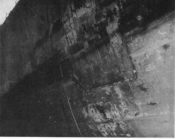
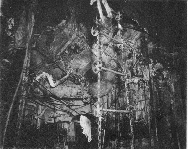
--91--
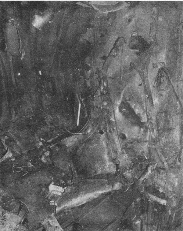
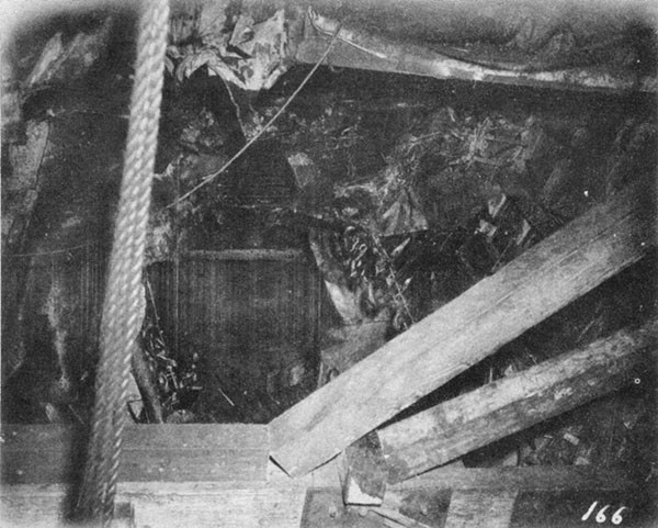
--92--
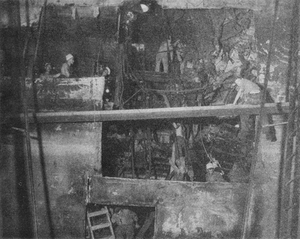
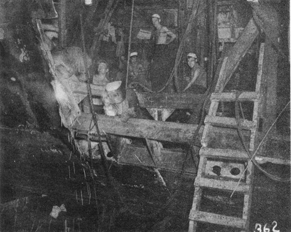
--93--
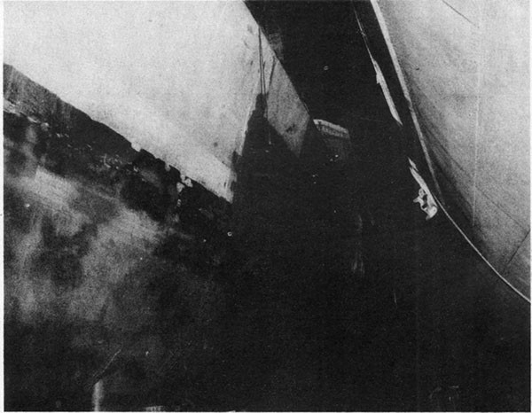
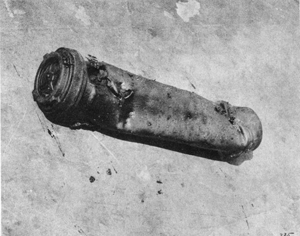
--94--
PLATE X
BOMB DAMAGE
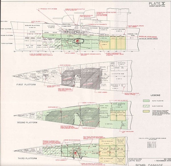
SECTION XI
U.S.S. ABNER READ (DD526)
Loss in Action
Leyte Gulf
1 November 1944
| Class | FLETCHER (DD445) | Length (O.A.) | 376 Ft. 6 In. |
| Commissioned | February 1943 | Beam (Extreme) | 39 Ft. 4 In. |
| Displacement | Draft (Estimated Mean, Before Damage) | ||
| (Standard) | 2050 Tons | 13 Ft. 8 In. | |
| (Before Damage) | 2925 Tons |
Reference:
(a) C.O. ABNER READ ltr. DD526/A16-3 of 13 November 1944 (Report of Action and Loss)
PHOTOGRAPHS 11-1 through 11-3 (Furnished by C.O. PENNSYLVANIA, BB38)
PLATE XI
--95--
U.S.S. ABNER READ (DD526)
11-1 Data for this section, in addition to the reference, has been obtained in informal discussions with ComDesDiv48 who was embarked in ABNER READ at the time of her loss and with the Commanding Officer of CLAXTON, who conducted the rescue of many of ABNER READ's survivors.
11-2 On the afternoon of 1 November 1944, while screening CLAXTON which had been damaged previously, ABNER READ suffered a surprise Kamikaze attack resulting in a crash just abaft the after stack. An intense gasoline fire ensued accompanied by the individual low order detonation of numerous rounds of ready service ammunition. Lack of firemain pressure permitted the fire to spread uncontrolled through the after end of the ship. About 10 minutes after the hit, a major explosion in the after magazines took place which caused the stern to sag and led to flooding which resulted in the ship rolling over to starboard and plunging by the stern 25 minutes later.
11-3 ABNER READ and CLAXTON were units of the screen of a large Seventh Fleet Task Group patrolling Leyte Gulf. At the time of the action the sea was calm, the breeze light and visibility excellent except for scattered high cumulus clouds. CLAXTON had been damaged during an air attack in the morning and had been directed to proceed to the transport area. ABNER READ was assigned to screen CLAXTON and zigzagged back and forth ahead at 15 knots with Material Condition BAKER set and her engineering plant completely split. At 1339 radar contact was made with "bogies" 10 miles distant. ABNER READ sounded General Quarters and began to set Material Condition ABLE. Within two minutes two VALs were sighted through the clouds at about 60 degrees relative bearing and about 6000 feet altitude. As the lead plane dived, ABNER READ commenced firing, and right full rudder and all engines ahead flank were ordered.
11-4 Despite heavy and accurate fire from 40mm and 20mm guns, the plane, in flames and with the port wing shot away, dived steeply downward across 40mm mount No. 3 and the after torpedo mount, then went over the port side. The starboard wing or the engine hit the 40mm director platform on the starboard side of the after stack, the breech end of the after torpedo tubes (trained 275 degrees relative) and the port 20mm machine guns. The latter were knocked over the side. An intense fire immediately engulfed the surrounding area. Material Condition ABLE had not yet been completely set. Only 6 rounds of 5-inch ammunition had been fired, all apparently by the two forward mounts.
11-5 Reference (a) reported that a bomb entered the forward starboard side of the after stack about 5 feet above the deckhouse top and exploded in the uptakes of the after fireroom. A shock simultaneously knocked personnel down in the fireroom and in the after engineroom. In the after engineroom the main distribution board on the starboard side was knocked down and caught fire, presumably from short circuits. Fires also broke out in the starboard side of the after fireroom and in the forward starboard corner of the after engineroom. One survivor from that engineroom made an otherwise unconfirmed report that the forward bulkhead was blown in on the starboard side.
11-6 On the bridge, as the plane was seen to crash into the ship, "Stop" was rung up on both engine-order telegraphs. This was answered by
--96--
the forward but not by the after engineroom. Telephones and MC circuits were tested and found intact forward, but no connection with a station abaft the hit functioned. Steering control and gyro circuits remained normal. Engine control reported the forward plant intact and the electrical load being taken on the forward board. As a result there was a momentary loss of power on fire-control circuits. The main battery (under director control) and 40mm mount No. 1 shifted targets to the second VAL which crashed in the water nearby. The topside fire meantime had forced the crews of 5-inch gun No. 3 and 40mm mount No. 5 (centerline aft) to clear their stations.
11-7 The watch in the after fireroom reported securing both boilers before they were forced by smoke and flames to evacuate the fireroom. In the after engineroom the main throttle was closed in response to the last stop signal from the bridge. This space also filled with smoke, personnel escaping via the after escape scuttle. It is of interest to note that all members of the fireroom and engineroom watch survived, although many were injured.
11-8 Fires immediately enveloped the after fireroom, the after engine-room, the adjacent living compartment C-201L and No. 3 upper handling room and shortly included the entire topside from the after smokestack to just abaft No. 3 5-inch gun (Photo 11-1). The after stack was reported to resemble a blast furnace emitting roaring flames and burning fragments. The forward repair party immediately led out hoses on the main deck from fire plugs 1-90 and 1-105, but firemain pressure failed. In the forward engineroom all available pumps were put on the firemain without succeeding in raising the pressure appreciably above 40 pounds. The after repair party was hopelessly marooned aft without light, power or firemain pressure. After setting depth charges on safe, leading out hoses and opening sprinkling valves of the after magazines, they were forced to abandon ship.
11-9 Since the after torpedo mount was on fire and the forward mount was subjected to intense heat and occasional flame, the order was given to jettison all torpedoes on the port beam. This was done expeditiously at the forward mount. All torpedoes were fired with tripping latches retracted and the torpedoes sank immediately. The after mount, engulfed in flames, was inaccessible. Within a few minutes ignition of the impulse charges occurred, resulting in the intermittent launching of five fully ready but highly erratic torpedoes.
11-10 About two minutes after the crash, a signal to back full was rung up to kill the ship's headway and prevent fanning the fire aft. This signal was followed by a stop bell. The forward engineroom answered both bells, after which the ship was dead in the water. The fire had now spread through the entire after deckhouse. The ready service ammunition, due to roasting, began to detonate low order singly at 40mm mounts 3, 4 and 5, at port and starboard 20mm mounts, in No. 3 upper handling room and at the port and starboard K-gun impulse charge stowages.
11-11 Additional hoses were led aft on the main deck from fire plugs 1-18 and 1-41 and from the port side of the forward engineroom. The available gasoline handy-billy was started, using overboard suction. An attempt to use electric submersible pumps to fight the fire was frustrated by lack of a suitably located power outlet. Firefighting personnel were hampered by intense heat, exploding ammunition and inadequate firemain pressure. Nearly all repair party personnel were injured in the effort to fight the fire. During this effort CLAXTON, standing by a few hundred yards off, made an effort to come alongside but an explosion, about three minutes after the hit in the vicinity of the after end of the
--97--
amidships deckhouse led to the decision to remain clear of the side and pick up survivors.
11-12 About six minutes after the initial plane crash, torpedo wakes were sighted on the port bow. The starboard engine was backed emergency full and 5-inch gun No. 1 and No. 2 40mm mount opened fire on the wakes. One or more torpedoes were actually sighted running erratically near the surface, one circling to within about 5 yards of the port side. It was believed that these were the torpedoes fired from the after mount.
11-13 About ten minutes after the plane hit, there was a very heavy explosion aft, below the waterline, which shook the entire ship. Immediately a sharp starboard list was noted. The main battery director jammed in train. A large hole in the starboard side in the vicinity of frame 160 with plating projecting outward was observed below the waterline. This explosion apparently occurred in No. 3 lower handling room which was an off-center compartment. KILLEN reported that ABNER READ appeared to blow up, flames spreading rapidly. The hull girder failed in way of the explosion, as evidenced by the stern section declining aft independent of the rest of the ship. Extent of flooding was not reported. Anticipating a series of magazine explosions, the Commanding Officer gave the order to abandon ship.
11-14 Before the abandon ship order had been fully carried out, the Captain noted that the fire and explosions had abated somewhat, probably due to flood water extinguishing some of the fires, countermanded his order and returned some men to the forward 5-inch and 40mm guns. Available life rafts were lowered, however, and the port motor whaleboat launched. Some 5-inch powder tanks were collected as additional floats. All below-deck spaces were cleared. The list slowly increased and explosions aft again grew in severity and frequency.
11-15 At 1358 about 15 minutes after the hit, the list reached about 20 degrees and the order to abandon ship was again given. This evolution took 7 minutes. At 1415 the list reached about 90 degrees and ABNER READ settled on her starboard side. Two minutes later she sank stern first in 35 fathoms. No depth charge or other underwater explosions followed, but a large fuel oil fire burned on the water for several hours over the area where she sank. The ship went down 35 minutes after the plane crash and 25 minutes after the lower handling room explosion. She rolled on her beam ends 10 minutes after the last survivor, the Captain, had left the ship.
11-16 Eye-witness accounts do not agree as to whether the plane carried bombs nor whether they were released before the crash. AMMEN (DD527) had this plane under fire and reported no bombs released. Some observers in ABNER READ neither saw a bomb attached to the plane nor released and falling. If a high-explosive bomb did strike the ship, it was probably no larger than the 63 Kg type in view of the limited extent of structural damage and the fact that all personnel escaped from the after machinery spaces. Possibly no high-explosive bomb was carried. The shock experienced could be attributed to the impact of the plane.
11-17 The speed of propagation and intensity of the fire which immediately engulfed the scene of the crash led both the Commanding Officer and the division commander to suspect that the plane carried some type of incendiary material, such as our napalm-thickened gasoline. Another explanation of the intensity of the fire could be that it was fed primarily by fuel oil, either spilled from lines in the bilges ruptured by the initial blast or pumped into the hot fire boxes after the fireroom was evacuated. Although the boilers were reported secured, it is possible that in the smoke-filled darkness the injured personnel in the after machinery spaces were unable to completely secure the fuel oil service system. The
--98--
"blast furnace" description of the after stack supports such a possibility, as does also the fact that a large fuel oil fire burned on the surface long after the ship sank (Photo 11-3).
11-18 Inability to cope with the fire was not due to a lack of courage on the part of the firefighters, all of whom were burned or wounded by fragments from exploding ammunition, but rather to the intensity of the fire and the unexplained failure to get adequate pressure on the firemain. The firemain was habitually split into a forward and an after section by closing valve 5-110-7 in the after fireroom near the forward bulkhead above the gratings. Reference (a) conjectured that the main was broken at a point between this valve and the fireroom bulkhead. No mention was made of any attempt to isolate the forward section by closing valve 5-100-8 in the forward engineroom. The two fire-and-bilge pumps and the fire-and-flushing pump in that space had a combined capacity of 650 GPM at 100 pounds per square inch - enough to operate ten or more 1-1/2-inch all-purpose fog nozzles. Full allowances of firefighting equipment were on board with the exception of one portable submersible pump. Sixty-five per cent of the complement had attended Navy Firefighter Schools.
11-19 Exactly what ammunition was involved in the explosions in ABNER READ and how its detonation was initiated, is, as usual, indeterminate and can only be surmised from indirect and circumstantial evidence. In many points the case of CALLAGHAN (DD792) is a close parallel. A suicide plane with one bomb hit her in way of the after engineroom disrupting all power, light and water services aft and disabling the after repair party. A severe fire quickly engulfed the after end of the ship. After four minutes an explosion occurred in No. 3 upper handling room apparently due to a mass detonation of about 75 rounds of 5-inch projectiles, initiated by the roasting effect of the fire. CALLAGHAN immediately thereafter assumed a 15-degree starboard list but the fire subsided. About an hour and one half later the vessel plunged by the stern with a heavy starboard list. Apparently, in ABNER READ there were two explosions which were greater than might have been produced by detonations of single projectiles or ignition of single powder charges. The center of the bright flames visible in photograph 11-1 is located at about frame 145 abreast No. 3 upper handling room and the forward port roller loader and depth charge projector. This was approximately the location of the explosion reported to have occurred as CLAXTON prepared to come alongside. It is probable that this blast consisted of group deflagrations or low order detonations in 5-inch ready service ammunition, since no distinct shock was reported but rather an eruption of flames and debris. The later and more distinct explosion did produce a severe shock and could be accounted for by a mass detonation of 5-inch projectiles in the lower handling room of No. 3 5-inch mount. The smoke cloud in photograph 11-2 has a mushroom shape typical of the clouds which have risen in way of magazine explosions. Its color is not indicative of the explosive involved because of the admixture of steam and water vapor. The degree of structural damage reported to have resulted from this explosion was not commensurate with the damage to be anticipated in a full-fledged powder magazine explosion. The latter type of explosion demolished the whole end of the ship in the cases of LINDSEY (DM32), SHAW (DD373) and LONGSHAW (DD559). In ABNER READ approximately 600 projectiles containing about one ton of explosive were normally stowed in C-301-M. The structural damage reported in ABNER READ corresponds to that to be expected from a mass detonation of a substantial portion of the projectiles carried in C-301-M.
11-20 The Commanding Officer suspected that the dredger hoist conducted the fire to the lower handling room. It was not reported whether
--99--
the hoist was open at the time of the hit, but owing to the surprise nature of the attack, this is doubtful. The lower handling room had scarcely been manned and apparently no rounds had been fired by No. 3 gun when the crash occurred, forcing immediate evacuation of the mount. In FRANKLIN (CV13) four closed armored 5-inch dredger hoists were engulfed in a prolonged fire. The covers at the upper end were blown off and charges and projectiles in the hoists were consumed, seriously damaging the hoist trunk, but the lower ends of the hoists were not damaged and no explosions occurred in the lower handling rooms. In ABNER READ it seems probable that the fire reached the lower handling room through open hatches or via burning oil which leaked in from the GC tanks after the impact and blast in way of the main deck above had ruptured adjacent structure.
11-21 No data are available on the extent of the flooding in ABNER READ nor on the liquid loading prior to damage. Her stability characteristics were such that capsizing and plunging were likely to occur if free surface included the after fireroom, the after engineroom, and three or more major compartments on the first platform aft. WILLIAM D. PORTER (DD579), a sistership, rolled on her side and plunged with similar flooding after her fantail submerged.
11-22 Reference (a) reported that the decision to abandon ship was based on the fact that the ship had listed through 18 degrees, half the angle at which the maximum righting arm developed on the curve of statical stability of the undamaged ship. Although the sea was calm, this list of 18 degrees was enough to keep the deck edge immersed. More important, however, were the criteria that structural failure aft had already taken place and both list and trim were steadily increasing. Seventeen minutes after the final decision to abandon ship was made, ABNER READ rolled over and sank rapidly stern first.
11-23 The frequent loss of power, lighting and firemain pressure to the after repair party in severely damaged vessels of the DD445 Class proved an embarrassing handicap in their damage control performance. Vessels of the later Classes, the 692 short and long hull, have markedly greater damage resistance because of their independent emergency generator, switchboard and fire pump located abaft the engineering spaces. So equipped, these ships are much better able to cope with such conflagrations as led to the loss of ABNER READ and CALLAGHAN. The cases of AARON WARD (DM34) and HUGH W. HADLEY convincingly demonstrated the effectiveness of the improved installation.
--100--
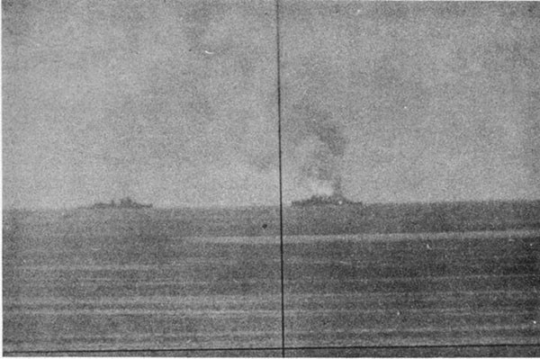
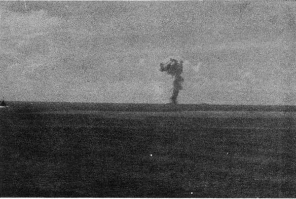
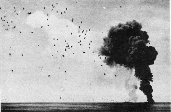
--101--
PLATE XI
BOMB AND SUICIDE PLANE DAMAGE
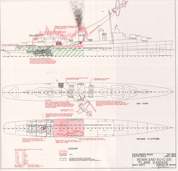
SECTION XII
U.S.S. HUGH W. HADLEY (DD774)
Bomb and Kamikaze Damage
Off Okinawa
11 May 1945
| Class | SUMNER (DD692) | Length (O.A.) | 376 Ft. 6 In. |
| Commissioned | November 1944 | Beam (Extreme) | 40 Ft. 10 In. |
| Displacement | Draft (Mean, Before Damage) | 13 Ft. 4 In. | |
| (Standard) | 2200 Tons | ||
| (Before Damage) | 2950 Tons |
References:
(a) C.O. HUGH W. HADLEY ltr. DD774/A16/al, Serial 066 of 15 May 1945 (Action Report)
(b) C.O. HUGH W. HADLEY ltr. DD774/A16/al, Serial 069 of 22 May 1945 (Damage Report)
(c) C.O. HUGH W. HADLEY ltr. DD774/A16-3/sk, Serial 094 of 6 July 1945 (Damage Report)
(d) C.O. HUGH W. HADLEY ltr. DD774/A16-3/sk, Serial 095 of 7 July 1945
(e) ComSerDiv 104 CSD104/L9-3/71:ht Serial 0845 of 26 August 1945
PHOTOGRAPHS 12-1 through 12-10 (Furnished by CO. HUGH W. HADLEY and ComSerDiv 104)
PLATE XII
--102--
U.S.S. HUGH W. HADLEY (DD774)
12-1 HUGH W. HADLEY with EVANS (DD552) participated in a notable engagement with Japanese aircraft on 11 May 1945 while on radar picket duty northwest of Okinawa. During the action approximately 100 enemy planes were destroyed through the coordinated efforts of the combat air patrol and the picket ships under the direction of the Fighter Director Team embarked in HADLEY. Both destroyers were severely damaged and immobilized by Kamikaze attacks. Following the action, accompanying small craft towed both ships to the lee of Ie Shima. After temporary repairs in the forward area, HADLEY was towed back to the United States and later stricken from the Navy list. Her initial report stated that the major damage had been caused by a Baka or piloted bomb, but subsequent information obtained after the vessel was docked did not indicate that this weapon was involved. Nevertheless, HADLEY's case is of more than usual interest because it was one of the most strenuous tests of the powers of survival of our 692 Class destroyer.
12-2 On the morning of 11 May 1945, HADLEY and EVANS were assigned with three LCS(L)'s and one LSM(R) to a radar picket station about 30 miles northwest of Ie Shima. The sea was calm with a light breeze, visibility unlimited to the north and east but obscured with mist and clouds in other quadrants. Large groups of enemy aircraft approaching from the north were picked up by radar about 0740. General Quarters stations were manned, Material Condition ABLE set and speed increased to 27 knots. Starting about 0745 five large raids totaling about 150 aircraft commenced attacks which lasted until 0930. Despite the heroic efforts of outnumbered Marine fighter pilots who continued to break up attacks after all their ammunition was expended, several Kamikazes finally scored hits on these two destroyers. About 0920 an enemy plane tore through HADLEY's rigging and crashed close aboard to port. A few minutes later a second Kamikaze, apparently the one mistaken for a Baka bomb, crashed into the starboard side at the waterline in way of the after fireroom (Photo 12-4, 12-5). The second plane's bomb apparently passed under the bottom and detonated some distance below the keel. A heavy explosion occurred simultaneously without smoke, flash or noise other than a dull thud. Extremely severe flexural vibrations ran through the ship for 20 seconds following the hit.
12-3 The three after engineering spaces flooded immediately to the waterline. The ship lost headway and commenced to take a starboard list, settling by the stern. Soon afterward, a third Kamikaze approached from astern, dropped a small bomb which struck in way of No. 4 40mm mount and then crashed into the superstructure abaft No. 2 stack, starting an intense fire in way of officers country aft and the 40mm clipping rooms (Photos 12-1, 12-2, and 12-3). Shock, fragment damage, blast and smoke rendered the ship's 5-inch and 40mm batteries entirely inoperable. Flooding spread to the shaft alleys and the machine shop (starboard side aft, first platform). As the starboard list increased, the Commanding Officer, fearing capsizing, ordered: "Prepare to abandon ship." The SG and SC radars, ECM and IFF gear were thereupon rendered inoperative and the registered publications were weighted and jettisoned.
12-4 Damage control personnel gave first attention to the fire. Employing all available pumps, portable and installed, eleven hose streams were directed on the flames. LCS(L)83 and LSM(R)193 came
--103--
alongside to starboard and to port, respectively, and assisted with their firefighting facilities, putting seven additional hose streams on the fire and providing additional foam, pumps, axes, etc., to HADLEY personnel. The fire was brought under control by 0945 and abandon ship preparations were then secured. The fire was finally extinguished about 1030.
12-5 As soon as the fire was under control, attention was focused on reducing the 7-degree starboard list which had increased from an initial 5 degrees. Fresh water in the starboard wing tanks B-7-W and B-9-W with an off-center moment of approximately 380 foot-tons was pumped overboard and depth charges along the starboard side were jettisoned. All torpedoes were also jettisoned and ammunition was thrown overboard as fast as it could be brought topside. Neither the total weight jettisoned nor the effect these measures had on the list or the freeboard was reported. However, after these steps were taken the danger of capsizing was no longer a matter of concern to the ship.
12-6 Unsuccessful efforts to reduce flooding were undertaken during the morning. Five submersible pumps were rigged to take suction in the machine shop and after engineroom through holes burned in the main deck. Very little progress was made, however, until after the ship anchored that evening in the lee of Ie Shima. Meanwhile, TAWAKONI (ATF114) came alongside to port at 1355 and sent a well-equipped salvage crew aboard. LSM(R)193 began towing from ahead at 1403 with the ships alongside assisting in controlling the tow. About 1700 DELIVER (ARS23) came alongside to starboard relieving LCS(L)83 and sent her salvage party to assist HADLEY.
12-7 After anchoring in Ie Shima about 1900, bulkheads 92-1/2 and 148 were heavily shored. To raise the stern, C-7-F, C-8-F, C-9-F and C-10-F were pumped out. The hatch in the machine shop leading to the starboard shaft alley was shored shut and the machine shop then pumped dry with a P-500 pump. The port shaft alley was also pumped out. On 14 May TAWAKONI towed HADLEY thirty-seven miles to Kerama Retto for docking and underwater repairs. During the six weeks before a dock became available, divers installed soft-patches and other flooded spaces were pumped out; details of this work have not been reported, but drafts reported when HADLEY docked were normal, indicating much of the flood water had been removed.
12-8 HADLEY docked in ARD28 on 24 June and remained in dock until 27 July. During this period ARD28 was towed 50 miles to Buckner Bay with HADLEY on the blocks. The unusual extent of the structural repairs required had not been anticipated despite the extensive underwater work accomplished prior to docking. Virtually complete restoration of longitudinal strength in the shell and longitudinals from frame 90 to 135 was necessary (Photos 12-8, 12-9 and 12-10). This work was accomplished by the ship repair unit personnel in ZANIAH (AG70). The excellence and thoroughness of these repairs were proved later when HADLEY safely rode out typhoon winds and seas while proceeding under tow to Saipan.
12-9 The character of the missile which caused the major damage in HADLEY will never be established with certainty. Reference (a) quite specifically identified it as a Baka bomb, stating that the bomb was observed to be released from a BETTY astern at an altitude around 600 feet and struck the starboard side at about frame 105. The following data subsequently discounted this information:
(a) Debris found in way of where the Baka was reported to have struck included an aircraft engine.
--104--
(b) The impact damage indicated the approach had been from forward of the beam rather than from astern.
(c) Baka releases were normally made at high altitudes, 20,000 feet or higher, so that the glide approach of the Baka could be made at a speed exceeding that of intercepting aircraft and such as to throw off the control of anti-aircraft fire.
Reference (d) stated that the damage was caused by a suicide plane and its bomb. A 12-inch diameter fail assembly was recovered from the wreckage, representing a bomb which the reference estimated to weigh about 500 pounds. The 12-inch diameter tail assembly corresponds to that carried by a 63 Kg GP bomb, but the extent of structural damage incurred greatly exceeded the disruptive powers of even the 250 Kg GP type.
12-10 Possibly the missile identified as a Baka was an influence torpedo, or a very large bomb perhaps as great as 800 Kg which detonated deep under the ship simultaneously with the suicide crash. EVANS reported narrowly avoiding one torpedo about 20 minutes before HADLEY was disabled. In any event the explosive charge involved was at least in the order of 600 pounds of TNT and was so fuzed that the detonation occurred at a considerable distance below the keel. This was evidenced by the absence of a large hole or even fragment holes in the bottom. The keel was hogged, however, to a maximum height of 55 inches near frame 114, the hogging extending a length of nearly 100 feet in the midbody (Photos 12-6 and 12-7). MAYRANT (1500 tons standard displacement), suffered damage of nearly equal severity following a near miss by a 500 Kg GP German bomb. Gases of comparable damage in heavier destroyers include MEREDITH (DD726)1, WADLEIGH (DD689)2, CHAS. J. BADGER (DD657)3 and RENSHAW (DD499)4, all involving heavy underwater ordnance.
12-11 The bomb which detonated at frame 145 in way of the No. 4 40mm mount was probably the usual 63 Kg GP type. The planes which crashed HADLEY were not identified other than being single engine types. Many types were present. EVANS identified among her attackers ZEKE, VAL, OSCAR, JILL, KATE and TONY.
12-12 The structural damage critically reduced the strength of the hull girder. The impact of the second Kamikaze tore a hole 9 feet high and 12 feet long in the starboard side with its upper edge about 6 feet below the main deck in way of bulkhead 110. The shock of the underwater explosion hogged and buckled the shell amidships in what appeared to be a compression failure. The ship was reported "to jump out of the water." This explosion amidships under the bottom set up a flexural vibration that caused shell failure in line with the after end of the skeg. Here the discontinuity of hull structure was manifested in circumferential buckling between frames 180 and 190. The main deck and superstructure around frame 56 also showed buckling. Ripples were noted in the main deck from frame 66 forward and from frame 80 to 170. Bulkhead 110 and 130-1/2 suffered compression failure and resultant buckling, as well as ruptures in way of the shafting which whipped.5 The starboard shaft sheared two forward couplings permitting the propeller to slide back until it jammed against the starboard rudder. The port shaft also parted at a forward coupling and slid aft 4 inches. Both after struts were thrown out of line due to the sag of the stern. The deckhouse between frames 114 and 170 was largely demolished by the impact, blast and fire following the third Kamikaze hit.
__________
1 German contact mine, English Channel, 8 June 1944
2 Japanese contact mine, off Palau, 16 September 1944
3 Depth charge from suicide boat, off Okinawa, 9 April 1945
4 Japanese submarine torpedo, off Mindanao, 21 February 1945
5 This casualty also occurred in cruisers. See War Damage Report No. 53 on HOUSTON (CL81) and War Damage Report No. 54 on CANBERRA (CA70)
--105--
12-13 While the slowly increasing starboard list caused considerable alarm as to the stability characteristics of the ship, the 2200-ton class may be considered a four-compartment ship; that is, four main compartments may flood to the waterline, yet the ship retain appreciable positive GM and freeboard. No exact computation of the GM in HADLEY after damage is practicable due to incomplete data; however, an approximation using pessimistic assumptions for missing data, gives 1.2 feet positive. For the ship before damage, GM was approximately 3.3 feet. The 5-degree initial list was due to off-center flooding and was not unusual. Possibly the increase to 7 degrees was due to the free surface effect of firefighting water which may have collected on the first platform deck aft. The danger of capsizing, however, was at no time serious.
12-14 About 1900 on the day HADLEY was damaged the wind suddenly became gusty, but the ship by this time was fortunately in the lee of Ie Shima. Had she still be[en] in unprotected waters the working of the weakened structure would have been extremely hazardous and would very likely have led to complete failure of the ship's girder with resultant loss of the ship.
12-15 The firefighting problem was greatly simplified by the availability of the two emergency electric fire pumps operated by the emergency Diesel generators. The forward one fed two 2-1/2-inch hoses and three 1-1/2-inch, while the after pump fed two 2-1/2-inch streams. In addition, two 1-1/2-inch hoses were led from the P-500 pump and one also from each of two handy-billies. The fire was mainly fed by gasoline from the Kamikaze crash, 40mm ready service ammunition and clothing and bedding in officers' quarters aft. Foam was extensively used in the firefighting. Assistance from the vessels alongside was extremely helpful since access fore and aft in HADLEY was cut off. The expeditious action of the firefighters undoubtedly prevented the conflagration from spreading disastrously to adjacent magazines, torpedoes and depth charges. This was accomplished despite extensive ruptures in the firemain in way of the after engineering spaces. It should also be noted that the volume of water applied to this fire was very large, being several times that employed in any other case in this report.
12-16 No flooded spaces were unwatered until after the ship was anchored. The measures taken underway to pump out flooded spaces were ineffectual. In addition to the ship's five submersible pumps, large capacity Diesel and gasoline salvage pumps with eductors provided by TAWAKONI and DELIVER were employed in an effort to reduce the water level in flooded compartments. It was finally determined that the pumps were merely circulating sea water and pumping efforts were suspended until after anchoring. At that time the hatch in the machine shop deck was shored shut and the space was then readily pumped out with a P-500 pump. The port shaft alley was pumped dry soon after. Subsequently, while at Kerama Retto, diving parties succeeded in securing soft patches which apparently permitted all flooded compartments to be pumped out, thereby improving trim and reserve buoyancy prior to docking.
12-17 Machinery damage obviously was so severe as to be beyond the scope of casualty control. The forward fireroom remained intact; however, the other three engineering spaces were not only flooded immediately, but machinery therein was damaged by shock to such extent that little was repairable except in the after engineroom. All bearings were completely wiped and journals badly scored on the forward main turbines. The forward reduction gears were stripped and galled, all bearings wiped and journals scored and the casing sprung. Starboard shafting was sprung, spring bearings were pulled off their foundations and stuffing boxes pulled out of the bulkheads. The port unit was apparently undamaged, however, except for submergence. Small diameter piping was extensively fractured and distorted. The master gyro was thrown heavily against its dome which
--106--
was shattered by the concussion. The ship's service electric power generation and distribution system was completely knocked out, but both emergency Diesel generators supplied power through the emergency boards.
12-18 Ordnance equipment throughout the ship was thrown out of alignment and damaged by the violent flexural vibrations. Hydraulic piping in all 5-inch mounts developed numerous leaks. The two after 40mm quads were demolished by direct hits. Torpedoes in the after mount did not add to the conflagration despite heavy fragment attack and severe roasting (Photo 12-3).
12-19 Radio equipment suffered extensively from shock. TBK, TBL and TAJ antenna were carried away by the first Kamikaze crash. Only the battery operated SCR610 remained operable after the attack. The ship was not specially fitted for picket duty except for the portable gear transferred from BROWN (DD546) by the Fighter Director Team a few days before the action.
12-20 HADLEY was so severely damaged that her fighting effectiveness was almost completely destroyed. Her hull strength amidships was reduced in such degree that structural failure was a major hazard. Restoration of either propulsion plant required several months work in a shipyard. An intense gasoline fire which cut off access fore and aft had to be combatted despite extensive damage to the firemain and submergence of most of the pumps. Nevertheless the ship survived. Many destroyers with much less damage have been lost. The most important factors in HADLEY's survival were probably the following:
(a) An adequate reserve of buoyancy, stability and hull strength.
(b) An adequate duplication of essential services and dispersion of vital equipment.
(c) Confident, competent firefighting personnel who had adequate equipment with which to work.
(d) Satisfactory subdivision and maintenance of watertight integrity.
(e) Prompt and effective assistance from salvage and repair facilities.
--107--
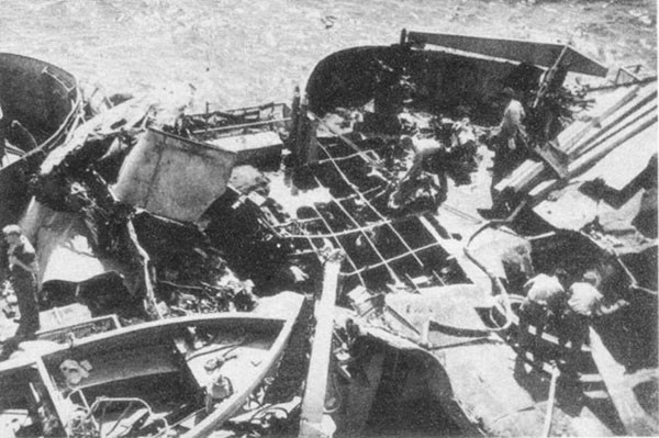
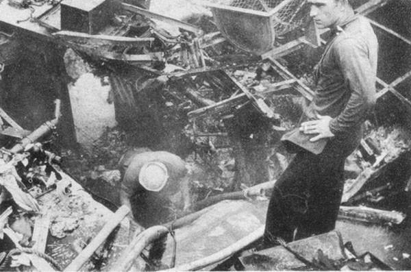
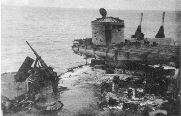
--108--
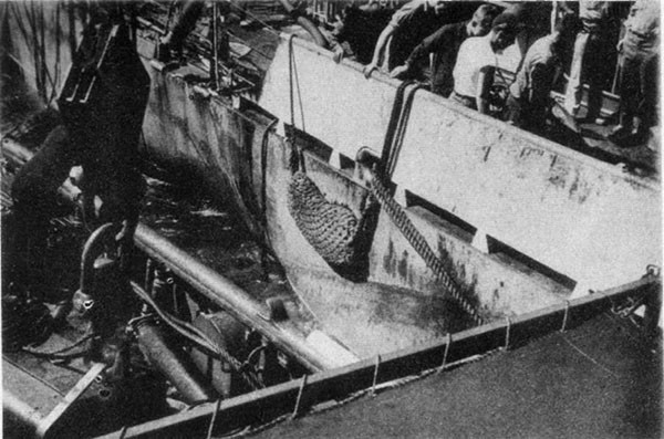
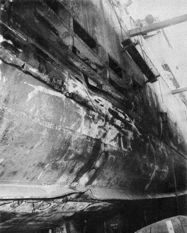
--109--
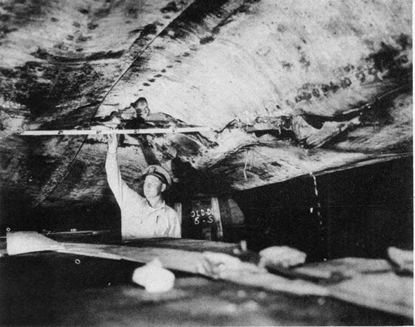
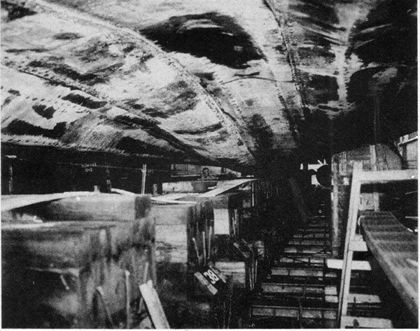
--110--
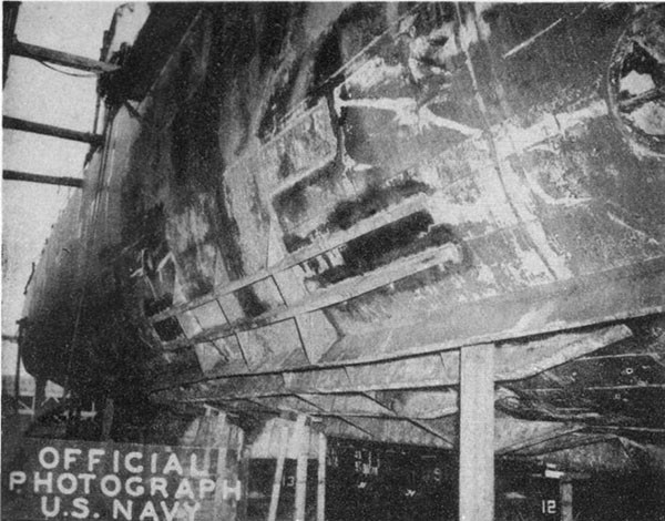
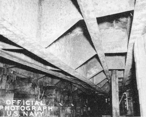
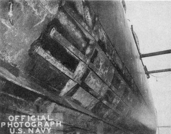
PLATE XII
BOMB AND SUICIDE PLANE DAMAGE
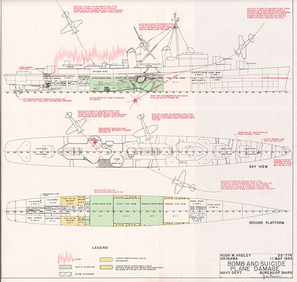
SECTION XIII
U.S.S. STORMES (DD780)
Bomb and Kamikaze Damage
Off Okinawa
25 May 1945
| Class | SUMNER (DD692) | Length (O.A.) | 376 Ft. 6 In. |
| Commissioned | February 1945 | Beam (Extreme) | 40 Ft. 10 In. |
| Displacement | Draft (Mean, Before | ||
| (Standard) | 2200 Tons | Damage) | 14 Ft. 0 In. |
| (Before Damage) | 3175 Tons |
References:
(a) C.O. STORMES ltr. DD780/A12, Serial 072 of 2 June 1945 (Action Report)
(b) C.O. STORMES ltr. DD780/A12, Serial 099 of 1 August 1945 (Damage Report)
(c) War Damage Report on Suicide Plane and Bomb Damage prepared by San Francisco Naval Shipyard, September 1946
PHOTOGRAPHS 13-1 through 13-8 (Furnished by CO. CURTISS (AV4) and San Francisco Naval Shipyard)
PLATE XIII
--112--
U.S.S. STORMES (DD780)
13-1 On 25 May 1945, in company with other picket vessels on station off Okinawa, STORMES was subjected to intermittent Kamikaze attacks. During one such attack an enemy plane released a bomb which penetrated to the lower handling room of No. 3 5-inch mount and apparently detonated at the shell near bulkhead 176. The plane itself simultaneously crashed into the after torpedo mount. No magazine or torpedo warhead explosion resulted. Extensive flooding took place aft, but the water level remained at about the first platform deck. Severe fires fed by the plane's gasoline and the 5-inch ammunition in No. 3 upper handling room were promptly brought under control. Despite the heavy structural damage which caused the stern to sag with consequent misalignment of shafting, the ship continued the action, employing speeds up to 25 knots for several hours after the hit. STORMES then proceeded to Kerama Retto for drydocking. After an inactive seven weeks waiting for a dock to become available, she docked in ARD13 at Buckner Bay for temporary repairs to structure and correction of shaft alignment to permit her safe return to San Francisco Naval Shipyard. After permanent repairs were completed in November 1945, STORMES reported for duty in the Atlantic Fleet.
13-2 The case of STORMES is singular in that it involved simultaneously a direct hit and high order burst in way of a magazine, a direct hit on a torpedo mount, a severe fire, partial structural failure of the ship's girder and serious misalignment of main shafting. It is also of interest that at the time of the action the ship had been in commission less than five months and the action described was her first; in spite of this lack of experience the excellence of the damage control performance in every respect was such that at no time was control of the ship or of the battery lost. Six members of her repair party were later decorated for their part in the action.
13-3 The damage report, reference (b), submitted by the Commanding Officer while the ship was in dock in ARD13 at Buckner Bay is clear and comprehensive and is therefore reproduced below in lieu of the usual narrative.
Fleet Post Office
San Francisco, California
1 August 1945
From: The Commanding Officer
To: The Chief of the Bureau of Ships
Subject: War Damage to U.S.S. STORMES (DD780)
Reference: (a) BuShips conf. ltr. C-FS/L11-1(374), C-EN28/A2-11 (of 10 April 1942) (b) PacFlt conf. ltr. 1CL-45
1. In accordance with references, the following report of war damage sustained by this vessel is submitted.
A. General.
On 25 May 1945, STORMES, in company with DD's DREXLER and AMMEN and LCS's 52, 61, 85, 89, was on radar picket station north of OKINAWA in Lat. 27-22.5N Long. 127-48.E. Following a night of continuous attacks by enemy aircraft, STORMES again went to general quarters at 0800I when aircraft were reported closing from the northwest. The vessels on station and a friendly combat air patrol consisting of 14 F4U's deployed to meet the approach. Weather conditions were becoming
--113--
steadily worse, and by 0900I visibility was decreased to about 4000 yards with a heavy and low overcast. Sea was calm with intermittent rain squalls further decreasing visibility. Depth of water over 500 fathoms.
0825 Observed C.A.P. splash one OSCAR bearing 340°T about 10,000 yards.
0903 Bogie closing from southward. Outer C.A.P. missed interception. CIC picked bogie but of the numerous friendly contacts on the SG-1 at a range of about 10,000 yards, but could not positively make radar identification by reason of the close proximity of friendlies who were saturating the SC scope with IFF. Control was on the bearing but was similarly hampered in defining the proper contact.
0904 Sighted enemy plane bearing 160° relative (ship on course 045° speed 20), through rain and overcast at range of about 4000 yards, target angle 060°, altitude 1500 feet. Two friendly fighters passed plane close aboard but going in opposite direction. Enemy plane immediately disappeared again. It was not until this moment of sighting that control definitely got on the target. The order to commence fire was given but there was a momentary delay caused by the presence of the two friendly fighters, and the relative position of the plane crossing astern which entailed firing over group five. As the plane was apparently headed away and across the stern, the ship swung left to bring all guns to bear. Plane emerged from cloud bearing 280° relative, position angle 30°, range about 2000 yards, and apparently headed for ship ahead (AMMEN) in a shallow dive. All batteries bearing opened up. With bursts apparently in close proximity of plane, plane executed a half loop at bearing 315° relative and came down in a twisting turn overhead at an angle of 60-70°; turned on his back, and struck the after torpedo mount. The plane released a bomb which penetrated the superstructure deck abaft of the torpedo mount and exploded in mount three magazine. The plane was later tentatively identified as a TOJO. Total firing time about twenty seconds with the battery in the following control set-up.
Mount 3 on Mk 37 director
Mount 2 on director 2
Mount 1 on director 1
By reason of the high elevation of the attacking plane, mount 1 could fire on director 1.
Ammunition expended (approx.) 6 rounds AAC; 120 rounds 40mm; 150 rounds 20mm. AMMEN had plane under fire with 5" and automatic weapons. DREXLER was not observed to fire. The plane was burning when he struck.
0906 Gyro compass tumbled, steering magnetic courses. Heavy fires reported on fantail and in after deck house. Jettisoned depth charges.
0920 Commenced firing at five unidentified planes coming out of rain, range about 4000 yards.
--114--
0921 Ceased firing, planes identified as C.A.P.
0925 All fires reported under control.
0950 Took position in column between AMMEN and DREXLER.
1043 Fire in #2 engineroom, lost steering control due to loss of power aft. Gyro compass settled on meridian. Steering with engines.
1053 Regained steering control with rudders. Fire in No. 2 engine-room out.
1055 All fires extinguished.
1115 Commenced firing at unidentified planes coming out of clouds at range about 4000 yards. Ceased firing when planes identified as friendly C.A.P. Total rounds expended during morning, 36 rounds AA Common; 246 rounds 40mm; 280 rounds 20mm.
1227 USS SPROSTON reported as escort back to base. Departed Radar picket station #15 on course 180°T speed 20 knots with SPROSTON astern in column.
1542 Anchored in 27 fathoms of water, HAGUSHI ANCHORAGE, OKINAWA SHIMA, near USS CRESCENT CITY to transfer wounded and dead.
At the time of being struck STORMES was accelerating from 20 to 25 knots and was in a hard left turn. After being struck, STORMES continued at 25 knots on various evasive courses, and at no time was control of the ship lost.
The immediate effects of the hit were as follows:
(1) After torpedo mount demolished and heavy gasoline fire started on superstructure and main deck in the immediate vicinity. Main deck strewn with wreckage.
(2) Intense fire in compartment C-204LM and in Mount Three upper handling room. Some fire in compartment C-205L.
(3) Heavy smoke billowing from Mount Three.
(4) Main power aft was secured at the after board except for steering control. Steering was later shifted to the emergency cable which thereafter carried the load.
(5) Due to whip caused by bomb explosion, gyro compass tumbled.
(6) After part of ship flooded to first platform deck between frames 170 to 186.
(7) Excessive vibration of the ship above 20 knots.
(8) Depth charges, and three war heads which were knocked to the main deck, were jettisoned.
(9) Remainder of armament and communications normal.
(10) Group five 20mm station temporarily abandoned due to smoke and flames.
--115--
In the opinion of the Commanding Officer, the immediate offensive fighting efficiency of the ship was reduced only by the amount of the loss of fire power aft, the reduction of maximum speed, and the temporary loss of the gyro. Ultimate inspection of damage showed that a speed of 20 knots could only have been maintained for about six hours more by reason of bent struts.
B. Direct Hit by Suicide Plane and Bomb
1. Except for demolishing the after torpedo mount and starting a gasoline fire, the damaging effect of the suicide plane was not in itself serious. The force of the impact caused the explosion of two air flasks which blew two tubes overboard together with their warheads. The remaining three warheads were knocked to the main deck and were jettisoned. The plane was completely destroyed by the impact and the resultant fire. Except for a piece of the wing and tail, the largest fragment recovered was part of a machine gun barrel and housing, and part of a connecting rod. An estimated 500 pound aerial bomb was apparently released just before the plane hit, and the bomb penetrated the superstructure deck just abaft the torpedo mount at frame 171 (1/4" al plate), emerged through after deck house at frame 172 (3/16" steel plate) and penetrated main deck at frame 173 (3/8" steel plate), berth deck at frame 176 (1/8" steel plate) and exploded at or in the deck of magazine C-305M in vicinity of frame 177. Estimated distance that bomb traveled before exploding - 28 feet. The resultant high order explosion blew gaping holes in the berth deck above into compartment C-204LM and the upper handling room of 5" mount three. The resultant fire in these spaces caused total destruction of material therein and in the gun mount above in addition to heavy personnel casualties. The downward force of the explosion tore a great hole in the ship's bottom on the centerline and extending from frame 176 to 186 with maximum athwartship dimension at frame 182. The rupture severed the keel and three longitudinals on either side and involved the structure of both intermediate struts with a resultant displacement. The stern of the ship sagged about six inches with wrinkling about the hull at frame 182. The structural damage involves all horizontal and vertical members below first platform deck between frames 170-186. The vertical members below torpedo mount and above first platform deck at frame 162 are buckled. The following bulkheads are wrinkled. Frame 170 from main deck down; frame 183 first platform down; frame 182 below first platform badly distorted, but watertight. Both shafts were bowed as a result of strut displacement but do not appear to be permanently bent. After struts, screws, and rudders undamaged. All electrical equipment and electrical cable in and passing through damaged areas require complete renewal.
Fragmentation of the bomb appeared to be considerable but no identifiable fragments were discovered except one small piece from the nose of the bomb. The destruction of racks, bulkheads, etc. in the magazine spaces was intense. Excepting the smoke from ignited powder in the upper handling room of mount three, no noxious fumes were noticed. This fire vented through mount three with resultant estimated total damage to equipment in the upper mount. Fire damage on the main deck and in the superstructure compartments was confined to that caused by burning gasoline in the immediate area and was quickly extinguished. However, total destruction of equipment in the after deck house resulted from the effects of impact together with the fire.
The fires were brought under control in about twenty minutes, and were extinguished in about two hours. Combative measures consisted of the employment of large volumes of water which by reason of the free flooding condition of the damaged area had no further adverse effect on stability. The distorted bulkheads below first platform deck at frame 182 were heavily shored, and bulkhead at frame 183 above first
--116--
platform was shored as a precautionary measure. Emergency power was furnished by jumper leads as necessary. In general, fire fighting equipment is considered highly adequate.
| AFT | FWD | |
| Draft before hit | 14 Ft. 8 In. | 13 Ft. 4 In. |
| Draft after hit | 17 Ft. 6 In. | 14 Ft. (Approx.) |
Waterline just below first platform deck level.
C. Emergency repairs
By reason of large work load, STORMES was unable to get into a repair dock until 17 July, and the exact status of underwater damage was unknown. Repairs are now being effected as follows:
(1) Damaged hull structure being cut away and renewed to repair rupture in hull.
(2) Hull being cut at frame 182 through horizontal members to permit stern to be jacked up. Stern has been jacked up 7-1/2" to bring after port strut in alignment with shaft line taken from the after stern tube bearing. It has been assumed that the after stern tube is true, and the shaft itself has been determined to be straight. The intermediate strut is being cut and will be fillet welded to bring it into alignment. The stern is twisted such that with the port after strut in alignment, the starboard after strut is not aligned. It has therefore been determined not to put the starboard shaft in commission. It is the present intention to return the vessel to repair yard on the port shaft alone. Temporary repairs will be completed about 15 August.
W. N. WYLIE
cc: CinCPac
OpNav
ComDesPac
13-4 In view of the extreme maneuverability of the plane and the size of the bomb, the enemy fighter which crashed STORMES, although tentatively identified as a TOJO, more probably was a ZEKE, similar in appearance but larger. ZEKE, as described in paragraph 2-15, was the name given a single seater fighter which weighed about 6000 pounds. It had a 36.2 foot wing span and could carry about 160 gallons of gasoline in installed tanks. Its maximum bomb load was about 300 Kg as compared with about 60 Kg for TOJO and it was reported to be the most highly maneuverable Jap Navy fighter encountered in the latter part of the war.
13-5 The size of the holes in the superstructure and main deck in way of the bomb's passage were about 18 inches in diameter in the narrow dimension, which tends to confirm the estimated size of the bomb. The limited radius of damage from blast and fragments was less than usually resulted from a 250 Kg SAP bomb hit. It is difficult to explain why tanks C-5-F, C-7-F, C-8-F, C-9-F and C-10-F were punctured while C-304-M remained intact. It is probable that powder stowed in C-305-M absorbed the fragments which normally would have pierced the bulkhead directly forward of the blast.
--117--
Judging by the flexural vibration caused and the slight amount of blast damage above the first platform deck, the point of detonation of the bomb is estimated to have occurred at the shell. The immediate flooding which followed, in STORMES as in KILLEN, probably accounts for the absence of a propellant powder explosion.
13-6 The structural damage resulting from the impact of the plane and the bomb blast was superficial in way of the upper flange of the hull girder, but destroyed the keel and bottom plating for a length of 20 feet near the after quarter point. The flexural vibration probably initiated the sagging of the stern abaft the damage. The deflection of the intermediate struts and sag of the stern caused the misalignment of shafting.
13-7 As mentioned in Section XII of this report the presence of rigid foundations for No. 3 twin mount above the after end of the skeg creates a "hard" point in the ship girder. In the basic design of the ship it was not practicable to extend the skeg farther aft to better bridge this discontinuity because to do so would have adversely affected the maneuverability of the ship. In STORMES, however, the blast damage to the underwater hull at this location would have created a hinge point abaft which sagging would take place even had the original structure been much stronger. To illustrate the sharp decrease in longitudinal strength that occurred in STORMES, Plate XIII shows the intact and damaged cross-sections at frames 170, 176 and 182 respectively, and the change in position of the neutral axis.
13-8 STORMES' fire fighting problem, aside from the switchboard fire in the after engineroom, was typical of those encountered by many ships following a Kamikaze crash and bomb blast in way of 5-inch mounts. HADLEY had a less dangerous blaze, slightly forward of that in STORMES and therefore clear of the after 5-inch mount. The bomb blast in STORMES cut power cables to the after electric emergency fire pump and the services of that pump were lost. However, the bomb detonated so deep in the ship that the firemain remained intact and pressure was available from pumps forward. STORMES is only one of numerous 692 DD's which promptly subdued a dangerous fire. The effectiveness of the fire protection system in the 2200-ton class has been repeatedly demonstrated.
13-9 With regard to torpedo behavior, the performance of those in the after mount was typical. The plane hit the mount squarely and two air flasks burst. The force of impact and sudden release of high pressure air knocked all the warheads off their after bodies. The air blast demolished those tubes in which the exploding flasks were housed. However, this was about the limit of damage caused by the exploding flasks. The performance of torpedoes in the forward mount of KALK (DD611) was almost identical under similar attack. From the standpoint of 5-inch ammunition behavior, STORMES' experience appears to have been a repetition of KILLEN's.
13-10 The ruggedness of the main shafting in operating for several hours after damage at speeds of 20 to 25 knots despite approximately six inches displacement of the after struts is quite remarkable. No permanent set nor any indication of failure developed, but outboard bearings became badly worn and required replacement. The ship's girder in a destroyer is relatively flexible. The change from hogging to sagging under various conditions of loading and in different positions with respect to wave crests may introduce a relative movement of the midships section with respect to the ends of 11.5 inches in DD445. Obviously, therefore, shafting alignment continuously varies in the intact ship and appreciable curvature over a long radius longitudinally is acceptable in a damaged vessel. ENTERPRISE (CV4[6]) is known to have operated for six weeks after near miss bomb damage in April 1945 with a shaft later determined to have been deflected about four inches at the main strut from the projected alignment of the bull gear.
--118--
LEUTZE (DD481) returned about 100 miles to port under her own power on one shaft after a plane crash and bomb hit almost severed the fantail. A subsequent check revealed that the steaming shaft had dropped 5 inches and moved inboard 2 inches at the after strut. KENDRICK (DD459) made a similar return with a shaft found to be out of line more than an inch and a half. It is notable that for the period required to clear the combat area a destroyer's mobility has rarely been interrupted by shaft misalignment. The ruggedness of main shafting and propellers has been repeatedly demonstrated. The limiting factor has been bearing wear rather than the strength or flexibility of the shafting.
13-11 The cause of the gyro casualty was not reported. The symptoms indicate a failure in the amplifier unit rather than a mechanical failure.
13-12 While STORMES was in dock in ARD13 at Buckner Bay, bad weather prevailed for almost two weeks and the dock rolled up to a reported angle of 15 degrees, requiring that the shores be constantly tended. The ship was not damaged by this motion, but it was not possible to carry on repair work concurrently. After undocking on 14 August brief sea trials were conducted successfully and STORMES proceeded to San Francisco Naval Shipyard for permanent repairs. Heavy weather was encountered off the California coast in which she rolled up to 50 degrees. STORMES arrived at San Francisco on 17 September 1945 without casualty. The repairs accomplished by ARD13 despite frequent enemy air attacks and persistent unfavorable weather proved entirely adequate.
13-13 The technique employed in the realignment of shafting in ARD13 at Buckner Bay was unusual and may be of some interest to other repair personnel confronted with a similar task in the forward area. Of STORMES' two shafts the displacement of the starboard was the greater; therefore, effort was concentrated on lining up the outboard bearings on the port side. The port propeller, both the main and the intermediate strut bearings and the tailshaft were removed. A bore-sight telescope was mounted on the stub end of the stern tube section of the port shaft parallel to the shaft axis. The shaft was then jacked over and, from the loci of points on the boresight circle, centerlines for the two after bearings were established and the exact displacement of struts determined. The side shell in way of frame 181-1/2 was then cut vertically down to the hole in the bottom and the stern was raised with several hydraulic jacks totaling 400 tons capacity until the port main strut was in line. The side shell was then rewelded in this position, repairs to bottom longitudinals and shell proceeded and the port intermediate strut was cut and rewelded to conform to the shaft line. The tailshaft was then reinstalled, and the bearings assembled with new bearing strips. The clearances thusly obtained were very close to the designed clearances, for the port shaft, but the twist in the structure aft left the starboard main strut 1-1/2 inches low. Owing to the heavy work load, no attempt to effect permanent repairs to the starboard shaft alignment was attempted but the intermediate strut was cut and rewelded to conform with the alignment of the main strut. At post repair trials satisfactory performance was obtained from the port unit but, as was to be expected, heavy vibration was noted at low RPM on the starboard shaft. For the homeward voyage therefore the starboard shaft, although available for emergency use, was locked by engaging the jacking gear and brake and the port unit only was employed.
--119--
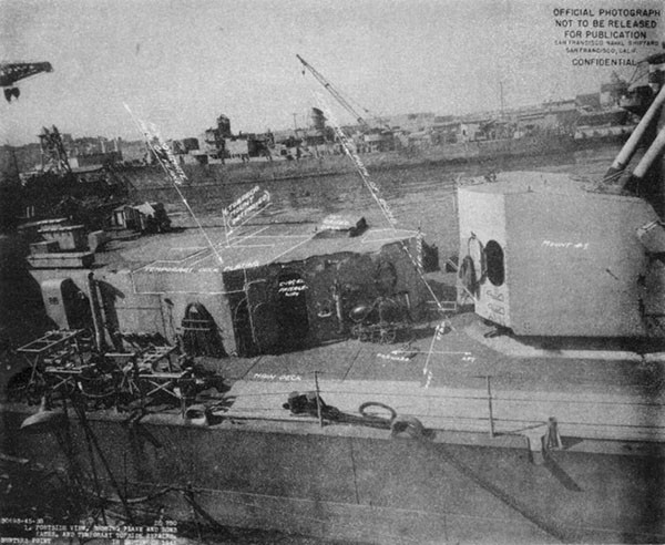
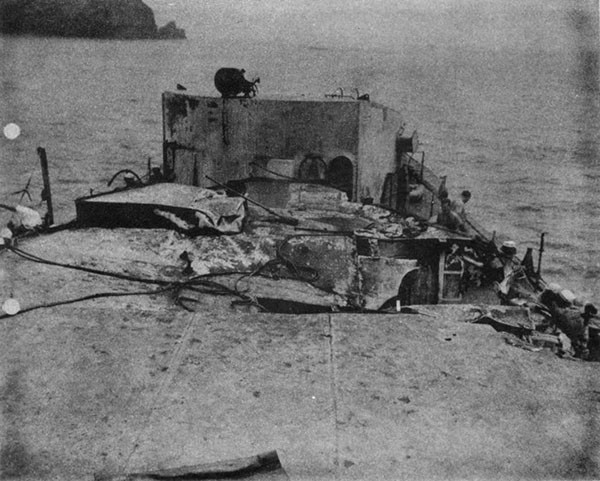
--120--
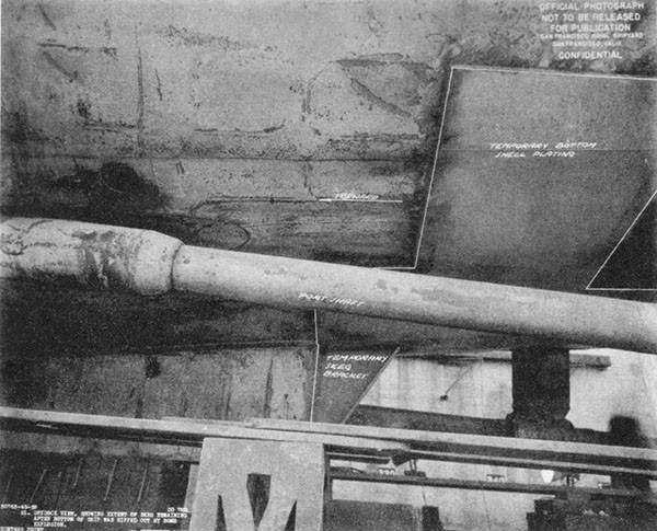
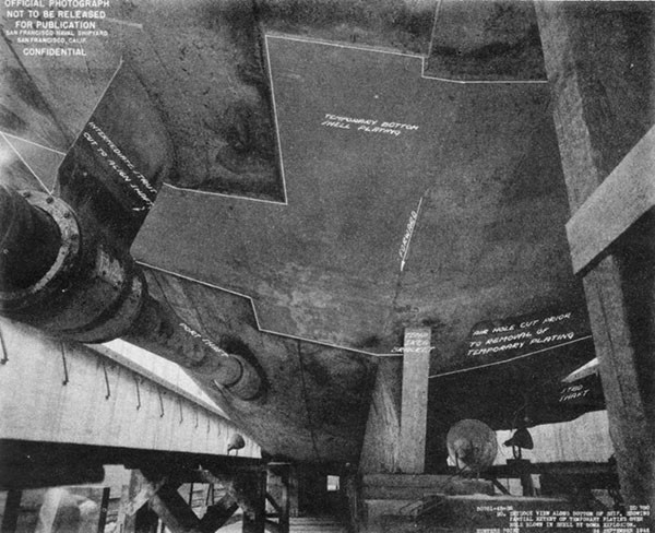
--121--
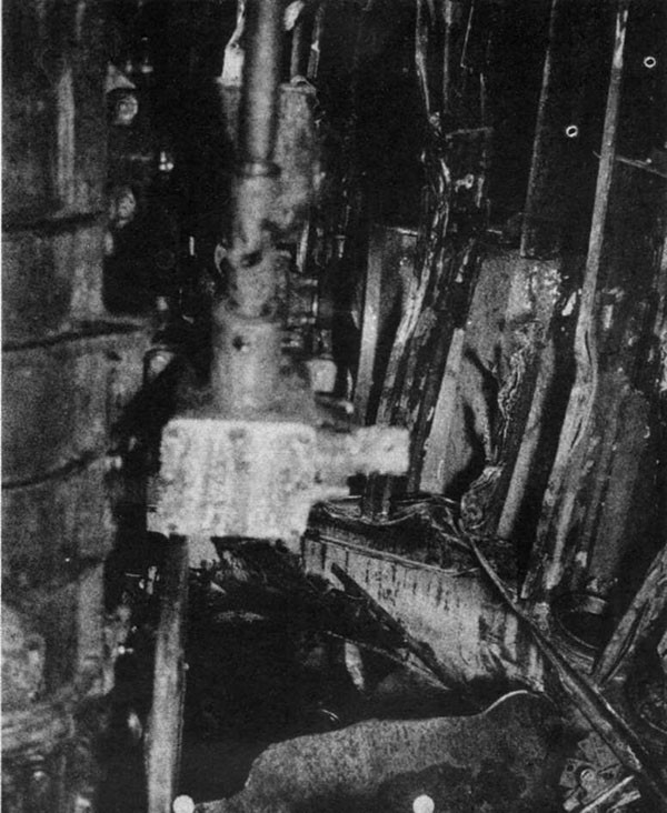
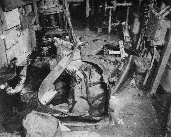
--122--
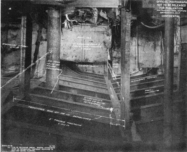
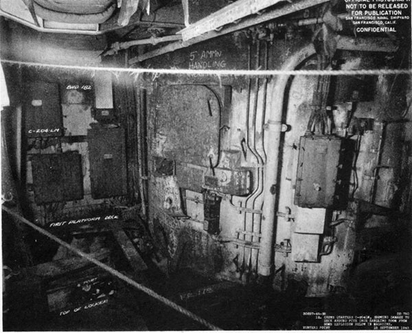
--123--
PLATE XIII
BOMB AND SUICIDE
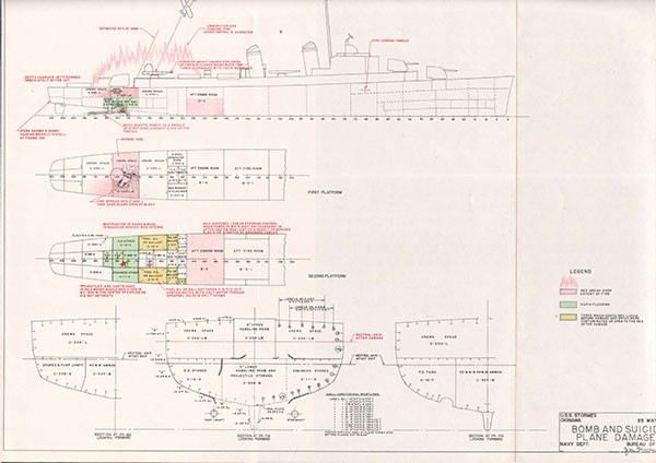
[END]


