Strut Your Stuff: The Use of Strut Channel as a Support System for Objects
(This article was originally published in Objects Specialty Group Postprints, Volume Twenty-Four, 2017.)
The Naval History and Heritage Command’s Conservation Branch has developed several means of supporting heavy objects, such as ship’s bells, using assemblies constructed from widely available strut channel and accessories.
1. Introduction
The Conservation Branch of the Naval History and Heritage Command (NHHC), founded in September 2015, opened a new state-of-the-art artifact conservation laboratory within the NHHC Collection Management Facility in Richmond, Virginia, in 2019. As equipment and resources were procured during the initial setup phase of the new facility, the Conservation Branch developed some workarounds, and what we believe are novel methods, for supporting objects utilizing strut channel.
Strut channel, also called metal framing channel, is a widely available “standardized formed structural system” (Wikipedia. s.vv. “Strut channel”) available in variations including lengths up to 20 ft. long with different permutations of perforations or slots. It is available in several electroplated galvanized finishes, electrogalvanized, as well as stainless steel alloys. One of its great strengths is that components are assembled with standard threaded fasteners to make weldless connections with simple tools, such as a hacksaw and wrench. It is commonly used in industrial spaces to support electrical wiring, network cables, and piping, and is known by several brand names, including Unistrut and Superstrut. It can be made into strong shapes utilizing easily available connector parts of various orientations.
2. Tilting Apparatus
Accessing the underside or interior of heavy objects can be harrowing; positioning and keeping a heavy object securely in a desired orientation can be difficult. Such is the case for many of the larger, heavier ship's bells in the NHHC collection, which are smooth, rounded shapes with few places to safely grip. Underside access may be needed to assess a bell’s interior condition (e.g., checking for the presence of paints containing lead pigments), to assess or remove the bell’s clapper mechanism, or to install hanging hardware.
Rather than relying on rope or strap rigging methods to try and access the interior of moderately sized bells, I devised a tilting rig constructed from sections of strut channel to tilt such bells to a 90 degree orientation, thereby allowing such access.
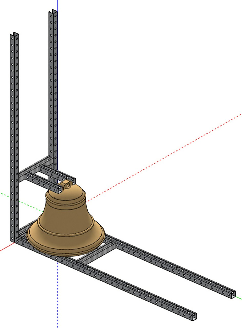
Fig. 1. Concept design for a tilting rig constructed from strut channel. (U.S. Navy photo by Naval History and Heritage Command Collection Management Facility staff/Released 180305-N-NO147-003)
This contraption acts as a second order lever. For example, when tilting a bell weighing 240 lbs. (“W”) with an opening diameter of 20 in. (“X”) and using standard 60 in. lengths of strut channel (“L”), we'd only need to provide 80 lbs. of force (“F”), as demonstrated in this equation:
F x L = W x X
F = (W x X) / L
e.g., F = (240 lbs. x 20 in.) / 60 in. = 80 lbs. of force
This threefold mechanical advantage is preferable to risking the physical safety of the person attempting to lift or tilt the bell’s entire weight of 240 lbs., or risk damaging the object by relying on a concentrated area of the object’s rim as the tipping point.
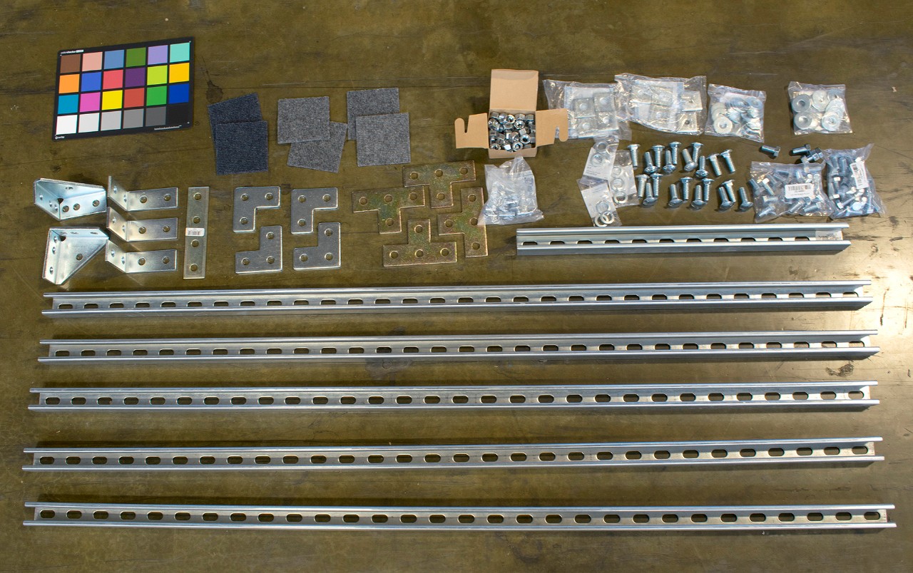
Fig. 2. A selection of strut channel and associated fittings. (U.S. Navy photo by Naval History and Heritage Command Collection Management Facility staff/Released 170515-N-NO147-001)
The actual assembly of this rig was accomplished using many of the components depicted in Figure 2. Standard 60-in. lengths of strut channel were joined with 90 degree strut corners to serve as the tipping point, with the ends of length mitered so that there could be two bolts through each length into this corner component. Flat corner brackets and 4-hole tee brackets were used to attach the cross-braces.
To construct the rig around an actual object I started by prefabricating the base section, with the lengths of strut channel spaced at a distance wide enough to support the object as well as allow underside access upon completion of the tilt. The outermost cross-brace was left off at this point, so that this prefabricated base assembly would be able to slide under the bell unencumbered, as the bell was elevated slightly with wooden cribbing at its center to accommodate the rail-like lengths of the base section. I slid the preassembled base section under the object and transferred the object’s weight to the strut channel rails of this base by removing the wooden cribbing. Pieces of cut cardboard tube and blue board were used to protect the bell’s rim from direct contact with the strut channel lengths.
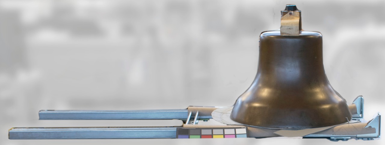
Fig. 3. The base section of the partially assembled rig with a bell in place. (U.S. Navy photo by Naval History and Heritage Command Collection Management Facility staff/Released 180305-N-NO147-001)
The outermost cross-brace could then be applied to the base section, as depicted in Figure 3. This was followed by attaching the two upright lengths of strut channel and both of the cross-braces. The upper cross-brace was positioned at a height just above the head of the bell, so that two cantilevered sections of strut channel could be attached to brace around the bell’s topmost extension, thereby preventing the bell from moving along the y-axis of the rig. Cardboard edge protectors and thick polyethylene sheeting were used to protect the surface of the copper alloy bell from these steel strut channel extensions.
The contoured gap between the back of the bell and the uprights was blocked with enough material to fill the space and help support the object when tilted, such as sections of wooden cribbing and wedges as well as polyethylene foam along the bell’s surface at the rear. Ratchet-strapping ensured no lateral movement.
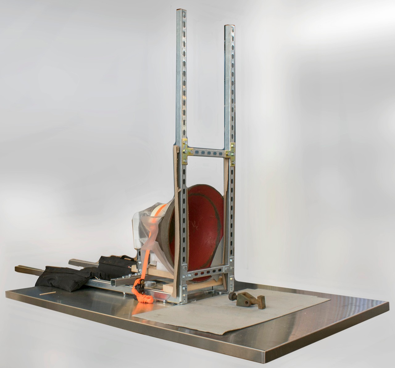
Fig. 4. The fully assembled rig on a tabletop in its tilted orientation, with an approximately 240 lb. bell attached, to make the underside and interior accessible, in this instance to assess the interior paint and remove the remnants of the clapper mechanism. (U.S. Navy photo by Naval History and Heritage Command Collection Management Facility staff/Released 180305-N-NO147-004)
Once this rig was fully assembled and the object was fully secured, the bell was tilted with force applied to the lengths of strut. Just before reaching the tipping point, a second person guided the bell down to its new orientation by carefully pulling on the strut channel lengths that were originally upright. Once in its final position, I had the option of applying weights to the strut channel lengths that were horizontal for an added sense of security, as depicted in Figure 4. The underside and interior of the bell were then accessible and relevant condition issues were addressed.
3. Mounting: A Case Study
The Conservation Branch was asked to develop a storage solution for a badly cracked 135 lb. ship’s bell from the Lassen-class ammunition ship USS Rainier (AE-5).
Typically, bells in the collection are stored by strapping them to a pallet, either above the waist or at the head. With this bell, we feared that strapping may add additional stress to the crack and risk propagating it, as illustrated in Figure 5.

Fig. 5. A mock-up demonstration of stresses that may occur in a cracked bell with the downward force from strapping at the top of the bell or above the waist. (U.S. Navy photo by Naval History and Heritage Command Collection Management Facility staff/Released 180305-N-NO147-006)
As an alternative to strapping, I proposed creating an interior column to provide support to the bell on the underside/interior of the bell. Although I first considered using a square steel tube (a.k.a., hollow structural section) to achieve this, I realized that it would require laborious modifications. Additionally, we did not have access to welding equipment.
Instead, I chose a component known as a post base, which is designed for use with strut channel and secures it in a vertical orientation perpendicular to this base.
Strut channel column load data provided by the manufacturer indicate that the length needed to support this particular bell, a length between 12 in. and 18 in., would be able to support column loads on the order of 10,000 lbs. (Thomas and Betts 2015). These column loads already incorporate safety factors but are clearly sufficient for a bell of this weight.
I sought a pallet as a surface upon which to attach the post base and found a 24 in. square high-density polyethylene (HDPE) pallet manufactured by Orbis, which is closer to the diameter of this bell and preferable to the larger standard sized pallet, 48 in. x 40 in. I drilled through the HDPE pallet and used bolts, washers, and nuts to secure the post base to it, as pictured in Figure 6.
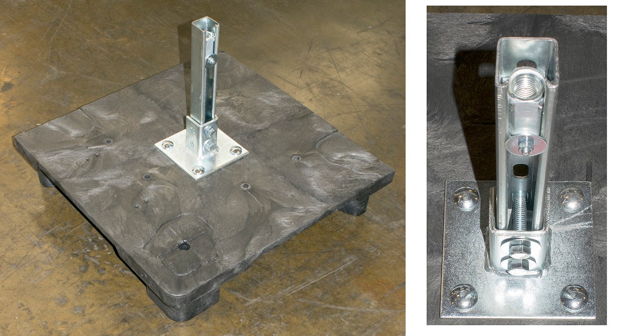
Fig. 6. The strut channel affixed to a pallet with a post base and hardware to serve as a mounting column, with inset detail of the strut channel component and accessories. (U.S. Navy photo by Naval History and Heritage Command Collection Management Facility staff/Released 180305-N-NO147-005
I installed a modified coupling nut through the hole in the bell’s head and secured it with a bushing and set screws, as pictured in Figure 7. Several washers and isolating layers were added to protect the interior paint layers as well as the bell metal surfaces.
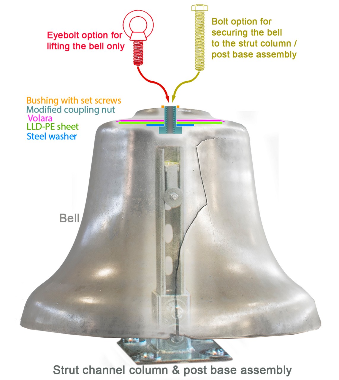
Fig. 7. A diagram illustrating the modified coupling nut, washers, and isolating layers attached to the USS Rainier bell prior to lifting and mounting. (U.S. Navy photo by Naval History and Heritage Command Collection Management Facility staff/Released 180305-N-NO147-007)
The added benefit of this threaded assembly attached to the bell was that it could be used not only secure the bell to the mount at the final step, but could also be used to lift the bell onto the column in the first place. We lifted it by using a shouldered machinery eye bolt in the coupling nut assembly on the bell in conjunction with a chain hoist and gantry.
Finally, once the bell was in place on the mount, I removed the lifting eye bolt and passed a longer bolt through the threaded assembly attached to the bell and into the second coupling nut that was secured earlier within the strut channel column.
Although more of the bell’s surface area is currently supported with the threaded assembly washers (relative to the surface area of the rim’s edge), the bottom of the supporting post base caused deflection in the HDPE pallet. This deflection occurred over the course of several weeks as we waited for the rim-supporting polypropylene shims to arrive. Fortunately, those shims worked well to distribute some of the weight at the rim and to alleviate most of the HDPE pallet deflection—however, such deflection may not have occurred in the first place if the shims had been used soon after mounting the bell on the strut channel column.
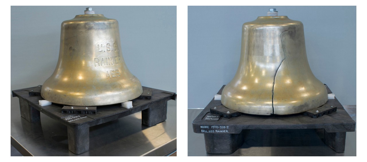
Fig. 8. The USS Rainier bell on its final, secured, strut channel assembly. (U.S. Navy photo by Naval History and Heritage Command Collection Management Facility staff/Released 180305-N-NO147-002)
Hopefully these strut channel systems will prove useful to conservators and others tasked with collections care. The affordability, ubiquity of component parts, and ease of assembly make strut channel systems a viable and attractive option for those in need of customizable solutions within the confines of limited resources. We will continue to develop strut channel for other applications and look forward to the adaptations made by others for varied collections materials.
Acknowledgments
I would like to thank my NHHC Conservation Branch colleagues, David Krop, Yoonjo Lee, Abigail Preston, and Melissa Swanson, for their work obtaining the materials used, help with implementing the assemblies, and for their overall support.
References
Thomas and Betts. 2015. Superstrut Metal Framing System. Accessed June 1, 2017.
https://www.reynoldsonline.com/ASSETS/DOCUMENTS/ITEMS/EN/TBCOH1041_2X6_Broc.pdf
Wikipedia. s.vv. “Strut channel.” Last updated May 31, 2017. https://en.wikipedia.org/w/index.php?title=Strut_channel&oldid=783177664
Further Reading
Lever Mechanical Advantage Equation and Calculator - Case #3. Engineers Edge, LLC. Accessed June 1, 2017. http://engineersedge.com/calculators/levers/page_levers_3.htm
by Karl Knauer, Conservation Branch, Naval History and Heritage Command
