Our Interactive Devices
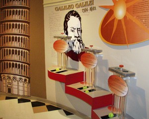
Falling Bodies Device
Learning Objective: To understand the principle behind Galileo’s Law of Falling Bodies (Gravity).
Method: The device consists of a pair of vertical acrylic tubes with a plunger-operated release mechanism at the top which serves to release a pair of tennis balls simultaneously into the tubes. One ball has been filled with BBs, making it noticeably heavier than the other. When placed into their recesses at the top of the tubes and released, both balls reach the bottom of the tubes simultaneously.
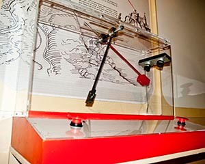
Galileo’s Pendulums
Learning Objective: To understand the principle behind Galileo’s Law of Falling Bodies (Gravity).
Method: The device consists of a pair of pendulums: one having a bob of cork; the other a bob of lead.When pulled back and released simultaneously, the operator will observe that the initial period (or swing) of both bobs is equal, despite their obvious difference in mass.
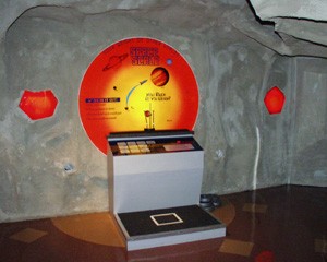
Space Scale
Learning Objective: To understand the relationship between weight and mass. (Gravity)
Method: The device consists of a scale and console with touchpads for ten locations in the solar system: Mercury, Venus, Earth, Mars, Jupiter, Saturn, Uranus, Neptune, Pluto, and Moon. When standing on the scale, the operator can select any of these locations and observe how his or her weight changes according to the gravitational pull created by the different masses of the celestial bodies.
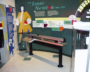
Frictionless Air Track
Learning Objective: To understand the principles contained in Newton’s Laws of Motion: Inertia, Acceleration and Action-Reaction.
Method: The device consists of a 1.5 meter aluminum beam connected to an air source. Air is blown through small holes at regular intervals the length and width of the beam, creating an air cushion along its surface. Two aluminum “cars” float freely on the air cushion when activated, allowing the operator to accelerate them in a variety of ways in a virtually frictionless environment. One car is equipped with a balloon-nozzle attachment which allows it to be self-propelled. Removable masses can be fitted to the cars to alter their masses for class group experiments.
Measuring Air Pressure Device
Learning Objective: To understand the relationship between air pressure and altitude in Earth’s atmosphere.
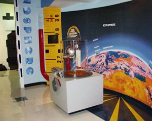
Method: The device consists of a large acrylic cylinder mounted on a cabinet with a rubber diaphragm in its base. A hand-operated wheel connected to a cam pushes up or pulls down on the diaphragm, increasing or decreasing pressure within the cylinder. A calibrated manometer tube provides a visual display of the atmospheric pressures at key geographic elevations on Earth.
Pressure Versus Altitude Device
Learning Objective: To understand the relationship between air pressure and altitude in Earth’s atmosphere.
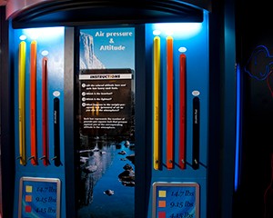
Method: The device consists of a series of weighted bars, each representing the weight of a 1″ square column of atmosphere at a given altitude. Operators can compare the atmospheric weights or pressures between sea level and intervals up to 50,000 feet above sea level (MSL).
Magdeburg Hemispheres
Learning Objective: To understand that air is matter which has mass and occupies space.
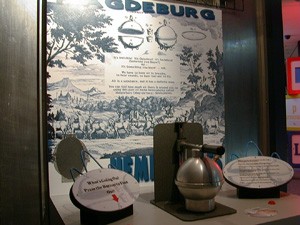
Method: The device mimics an experiment conducted by Otto von Guericke in Magdeburg,Germany in the 17th century. Two machined aluminum hemispheres are mounted to the top of a cabinet, one fixed and the other mounted on a vertical sliding track which allows it to be moved up and down to form a sphere. With the valve on the upper hemisphere closed and the two hemispheres placed together, a button-actuated vacuum pump removes the air from within the sphere and prevents separation of the two hemispheres.
Descartes Divers
Learning Objective: To understand Archimedes’ principle of buoyancy and gas volume vs. pressure (Boyles Law).
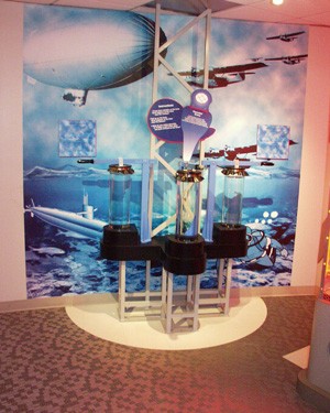
Method: The device consists of a water-filled cylinder topped by a lever-operated diaphragm. Two glass Cartesian “divers” or air-filled buoys are suspended in the cylinder. Operation of the lever either increases or decreases pressure on the water column, directly compressing or expanding the volume of air within each diver and causing the diver to ascend or descend.
Helium Balloons
Learning Objective: To understand the principle of buoyancy.
Method: The device consists of a tethered, helium-filled weather balloon beneath which is suspended a small basket. The operator can experiment with different payloads to achieve positive, neutral or negative buoyancy.
Weight of Gases Device
Learning Objective: To understand the variations in density and weight of the volume of given gases that are components of air.
Method: The device consists of a series of weighted bars each representing the weight of 100 cubic feet of a given gas: Oxygen, Carbon Dioxide, Nitrogen, Argon, Hydrogen and Helium.
Bernoulli Blower
Learning Objective: To observe an application of Bernoulli’s Principle.
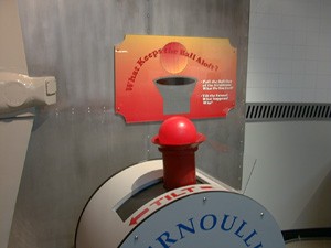
Method: The device consists of a cabinet-enclosed blower and a swiveling air exhaust plenum and ball. When actuated, exhaust air holds the ball in suspension 2-3 feet above the plenum. Operator can rotate plenum to 45° from the vertical and observe that ball remains suspended within the air column.
Captive Mentor Wind Tunnel
Learning Objective: To illustrate how the movement of aircraft control surfaces (elevator, aileron and rudder) affects the control and stability of an aircraft in the axes of pitch, roll and yaw.
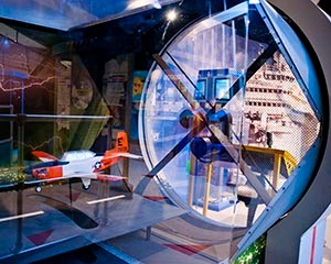
Method: The device consists of a large wind tunnel containing a 1/16 scale T-34C “Turbomentor” remote-controlled model. Operator sits at a control console equipped with stick, throttle and rudder pedals and flies model in the wind tunnel. Limited control authority and area restrict movement to approximately 3 feet up and down and 3 feet left and right.
Interactive Flight SimulatorLearning Objectives:
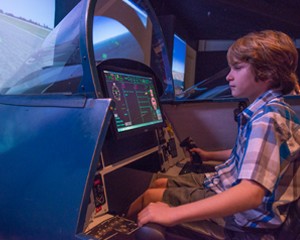
Method: The flight simulator is a highly interactive, highly realistic depiction of the flight environment. The hardware is configured to resemble a hybrid F-18/F-16 jet aircraft cockpit with a full set of controls and basic instruments. Out-the-window view from the cockpit is a wide-angle projection 10 feet wide by 8 feet high. The flight simulator may be configured to provide a concise, “canned” flight program which takes operator through a specific, limited profile (e.g. final approach to a selected runway), or it can be configured to provide an open flight program of unlimited duration and mission profiles. |
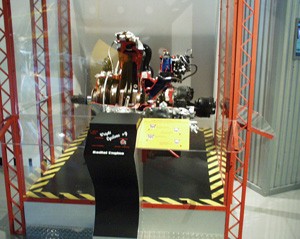
Wright Cyclone R-1820 Radial Engine
Learning Objective: To illustrate the mechanical operation of the piston, crankshaft and supercharger of the Cyclone engine.
Method: An operating cutaway of the Cyclone engine shows the mechanical movements of one of the nine pistons and its connecting rod to the engine crankshaft and reduction gearing to the propeller driveshaft. The centrifugal impeller for the supercharger is also displayed.
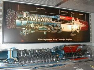
Westinghouse J-34 Turbojet EngineLearning Objective: To illustrate the mechanical operation of the compression and power turbine sections of a turbojet engine. Method: An operating cutaway of the J-34 engine shows the mechanical rotation of the driveshaft and the compression and power turbine sections it connects. Fiberoptic Display of the J-34Learning Objective: To understand how a gas turbine engine operates: the four stages of power production and how the engine converts fuel and air into thrust. Method: The fiberoptics in the display above the J-34 cutaway are keyed to buttons on a visitor-operated console which correspond to different sections of the engine and steps in the power-production cycle. |
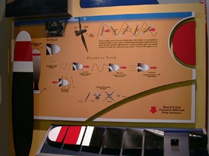
Propeller Display
Learning Objective: To observe how a propeller is designed like a “wing with a twist.”
Method: The device consists of a series of cross-sections of a Hartzell propeller blade from a T-34 aircraft. Visitors can observe the sections and compare their shapes with others taken from the same blade.

